15. Networking and communications
Assignments for week 14 :
-
This week we have a group assignment and an individual assignment .
-
The group assignment for this week is to send a message between two projects .
-
The individual assignment for this week is to design, build, and connect wired or wireless node(s) with network or bus addresses .
The goal for this week is to learn about the network and communications, and to learn how to connect two circuits either wireless or with wires using so many Techniques such as bluetooth modules, radio modules and wifi modules.
Files to download
I have included all the files that you can download down below and here you can find them directly :
Group assignment :
- For the group assignment this week we have to send a message between two projects and we successfully made this group assignment by sending a message using Netcat which i will explain about more .
What is netcat ?
-
Netcat is a computer networking utility for reading from and writing to network connections using TCP or UDP.
-
The command is designed to be a dependable back-end that can be used directly or easily driven by other programs and scripts.
-
At the same time, it is a feature-rich network debugging and investigation tool, since it can produce almost any kind of connection its user could need and has a number of built-in capabilities.
What is TCP ?
-
The Transmission Control Protocol (TCP) is one of the main protocols of the Internet protocol suite.
-
It originated in the initial network implementation in which it complemented the Internet Protocol (IP). Therefore, the entire suite is commonly referred to as TCP/IP.
-
TCP provides reliable, ordered, and error-checked delivery of a stream of octets (bytes) between applications running on hosts communicating via an IP network.
-
Major internet applications such as the World Wide Web, email, remote administration, and file transfer rely on TCP, which is part of the Transport Layer of the TCP/IP suite. SSL/TLS often runs on top of TCP.
-
TCP is connection-oriented, and a connection between client and server is established (passive open) before data can be sent. Three-way handshake (active open), retransmission, and error-detection adds to reliability but lengthens latency.
-
Applications that do not require reliable data stream service may use the User Datagram Protocol (UDP), which provides a connectionless datagram service that prioritizes time over reliability. TCP employs network congestion avoidance.
-
However, there are vulnerabilities to TCP including denial of service, connection hijacking, TCP veto, and reset attack. For network security, monitoring, and debugging, TCP traffic can be intercepted and logged with a packet sniffer.
What is UDP ?
-
In computer networking, the User Datagram Protocol (UDP) is one of the core members of the Internet protocol suite.
-
With UDP, computer applications can send messages, in this case referred to as datagrams, to other hosts on an Internet Protocol (IP) network. Prior communications are not required in order to set up communication channels or data paths.
-
UDP uses a simple connectionless communication model with a minimum of protocol mechanisms. UDP provides checksums for data integrity, and port numbers for addressing different functions at the source and destination of the datagram.
-
It has no handshaking dialogues, and thus exposes the user’s program to any unreliability of the underlying network; there is no guarantee of delivery, ordering, or duplicate protection. If error-correction facilities are needed at the network interface level, an application may use Transmission Control Protocol (TCP) or Stream Control Transmission Protocol (SCTP) which are designed for this purpose.
-
UDP is suitable for purposes where error checking and correction are either not necessary or are performed in the application; UDP avoids the overhead of such processing in the protocol stack. Time-sensitive applications often use UDP because dropping packets is preferable to waiting for packets delayed due to retransmission, which may not be an option in a real-time system.
Group meeting :
-
We had a group meeting in order to understand more about the group assignment and finish it .
-
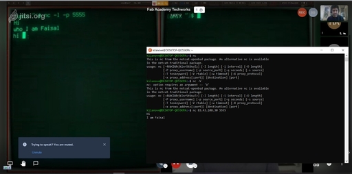
In order to send a message between two computers we used Netcat as i mentioned before, so we added The IP addresses for both and started the communication :
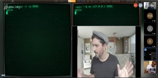
- Here you can see that we started the communication between the two computers My colleague faisl and fran :
- And here we are seeing how this communication actually happens and exactly the places and routers that made this communication work :
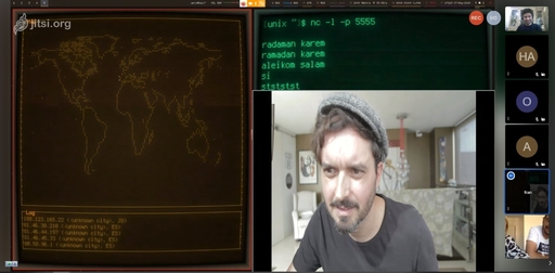
And thats all for the group assignment .
Individual assignment :
For the Individual assignment this week i have to design, build, and connect wired or wireless node(s) with network or bus addresses and to do that, first i want to use the bluetooth modules HC-05 in order to communicate between two boards as a master slave then use my Hello Board from week 7 in order to connect the attiny44 with the arduino using The bluetooth modules HC-05 , so lets start !!!
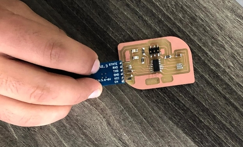
What is HC-05 and where to use it ?
-
The HC-05
 is a very cool module which can add two-way (full-duplex) wireless functionality to your projects.
 -
You can use this module to communicate between two microcontrollers like Arduino or communicate with any device with Bluetooth functionality like a Phone or Laptop.
-
There are many android applications that are already available which makes this process a lot easier, the module communicates with the help of USART at 9600 baud rate hence it is easy to interface with any microcontroller that supports USART.
-
We can also configure the default values of the module by using the command mode, So if you looking for a Wireless module that could transfer data from your computer or mobile phone to microcontroller or vice versa then this module might be the right choice for you.
How to Use the HC-05 Bluetooth module ?
-
The HC-05 has two operating modes, one is the Data mode in which it can send and receive data from other Bluetooth devices and the other is the AT Command mode where the default device settings can be changed.
-
We can operate the device in either of these two modes by using the key pin as explained in the pin description which i will show you down.
-
It is very easy to pair the HC-05 module with microcontrollers because it operates using the Serial Port Protocol (SPP). Simply power the module with +5V and connect the Rx pin of the module to the Tx of MCU and Tx pin of module to Rx of MCU.
-
During power up the key pin can be grounded to enter into Command mode, if left free it will by default enter into the data mode.
-
As soon as the module is powered you should be able to discover the Bluetooth device as “HC-05” then connect with it using the default password 1234 and start communicating with it.
HC-05 Technical Specifications :
-
Serial Bluetooth module for Arduino and other microcontrollers
-
Operating Voltage: 4V to 6V (Typically +5V)
- Operating Current: 30mA
- Range: <100m
- Works with Serial communication (USART) and TTL compatible
- Follows IEEE 802.15.1 standardized protocol
- Uses Frequency-Hopping Spread spectrum (FHSS)
- Can operate in Master, Slave or Master/Slave mode
- Can be easily interfaced with Laptop or Mobile phones with Bluetooth
- Supported baud rate: 9600,19200,38400,57600,115200,230400,460800.
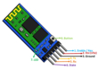
Pin Configuration :
- Here is the pin Configuration for the HC-05
| Pin Number | Pin Name | Description |
|---|---|---|
| 1 | Enable / Key | This pin is used to toggle between Data Mode (set low) and AT command mode (set high). By default it is in Data mode |
| 2 | Vcc | Powers the module. Connect to +5V Supply voltage |
| 3 | Ground | Ground pin of module, connect to system ground. |
| 4 | TX – Transmitter | Transmits Serial Data. Everything received via Bluetooth will be given out by this pin as serial data. |
| 5 | RX – Receiver | Receive Serial Data. Every serial data given to this pin will be broadcasted via Bluetooth |
| 6 | State | The state pin is connected to on board LED, it can be used as a feedback to check if Bluetooth is working properly. |
| 7 | LED | Indicates the status of Module : 1. [Blink once in 2 sec: Module has entered Command Mode] 2. [Repeated Blinking: Waiting for connection in Data Mode] 3. [Blink twice in 1 sec: Connection successful in Data Mode] |
| 8 | Button | Used to control the Key/Enable pin to toggle between Data and command Mode |
What is AT commands ?
- AT commands mode is used to change default settings of Bluetooth module.. When if there some need like to change the BT device name, device role like master or slave, Password of device BT module need to set in AT Command mode and default setting can change .
Using the HC-05
- Now after i have explained everything about the bluetooth modules its time to use them and here is the process :
LED and potentiometer :
-
My first idea was to control The LED using a potentiometer .
-
I have set the potentiometer to be the master and the LED to be a slave And in order to do that i had to control and program the Modules using AT commands .
-
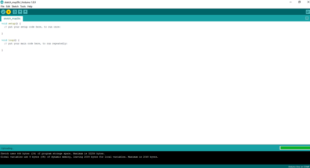
First i Have set the first module to be a slave and to do that connect your arduino and upload a blank sketch after making sure to set the right board and port like this :
-
Next disconnect the arduino from the laptop and connect the module, the connections are RX to RX, TX to TX, Vcc to 5V, EN to 3.3V and finally gnd to gnd .
-
Now when you connect the arduino to the laptop you will notice that the module is Blinking in short rapid and that means its in pairing mode .
- And in order to enter the AT Command mode you have to disconnect the arduino from the laptop, press the button on the bluetooth module and while pressing connect the arduino to your laptop, the module now will start to show long slow blinks and that means its in AT command mode .
- Now you can set the module to slave and to do that go to serial monitor and type AT, an error message will appear dont worry and type AT Again, it will show an Ok message and that means you are in, to make the module slave you have to do two things and its to change the role of the module and to get the modules address, you can see this in the video below :
- Next we have to make the second Module a master and to do that Repeat the previous steps and when you get to the role change it from 0 to 1, and make sure that the connection mode is set to 0 and that means it can only connect to one device only and finally put the slave address in order to connect to it and here is the whole steps explained in the video :
-
Finally you can test if the modules are connected by connecting each module to an arduino but you have to change the pin connections in which the EN pin is removed and the TX Goes to RX Also the RX goes to TX.
-
And a final note when you upload a code make sure to unplug the TX And RX pins .
Programming The Arduinos
- In order to connect both modules i have written this code :
// Master code

int PO = A0;

int A = 0;

void setup() {
  // put your setup code here, to run once:
Serial.begin(38400);
}

void loop() {
  // put your main code here, to run repeatedly:
//communication
int x=analogRead(PO);
if (x==0){
 A = 1 ;
}

if (x>400){
  A = 2 ;
}
  Serial.write (A);       //send the value of A to the other chip
  Serial.print (A);
  Serial.print ("    ");
Serial.println(x);
}
// Slave code

int red=2;


void setup() {
  // put your setup code here, to run once:
Serial.begin(38400);
pinMode (red,OUTPUT);
}

void loop() {
  // put your main code here, to run repeatedly:

 byte x=Serial.read()  ;    //recieve the signal from the other chip
Serial.println(x);
switch(x){

        case (1):{        //FISRT case is to turn the red LED off  (recieved 1 from the master)
             digitalWrite(red,LOW);
        }
        break;
        case (2):{      //SECOND case is to light the red LED when the signal is too high (recieved 2 from the master)
             digitalWrite(red,HIGH);
        }}
}
Hero shot for the LED and potentiometer :
Servo motor and potentiometer :
-
My second idea is to control the Servo motor using the potentiometer .
-
I have set the potentiometer to be the master and the servo to be a slave And in order to do that i had to control and program the Modules using AT commands .
Programming The Arduinos
- In order to connect both modules i have written this code :
// Master code

int state = 0;
int potValue = 0;
void setup() {
  Serial.begin(38400); // Default communication rate of the Bluetooth module
}
void loop() {
 if(Serial.available() > 0){ // Checks whether data is comming from the serial port
    state = Serial.read(); // Reads the data from the serial port
 }

 // Reading the potentiometer
 potValue = analogRead(A0);
 int potValueMapped = map(potValue, 0, 1023, 0, 255);
 Serial.write(potValueMapped); // Sends potValue to servo motor
 delay(10);
}
// Slave code


#include <Servo.h>
Servo myServo;
int state = 20;
void setup() {
  myServo.attach(9);
  Serial.begin(38400); // Default communication rate of the Bluetooth module
}
void loop() {
 if(Serial.available() > 0){ // Checks whether data is comming from the serial port
    state = Serial.read(); // Reads the data from the serial port
 }
 // Controlling the servo motor
 myServo.write(state);
 delay(10);
}
Hero shot for the servo motor and potentiometer :
ATtiny44 and HC-05 :
- The second idea was to connect an Attiny44 to the bluetooth module and while doing that i had some fails so i will go throw my fail and how i have fixed it :
Fails and how i debugged those fails :
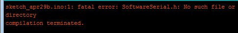
- The irst thing happened to me while working on the attiny44 and programming it that a weird error message which saying : “No such file or directory” kept showing while compling the code even when the SoftwareSerial library is download and added like this :
- So in order to know how to fix that i spent more than 10 hours just trying to work with the code and trying to added the library from the library manager then after researching i have found that this problem is common and it happens for many reasons which are : 1st make sure that the library name in the arduino file is the same as the one inside the software, 2nd the problem may be form the software itself maybe its crashing or you are not downloading the right version, 3rd which was my case try to use the other version of Arduino which is Arduino IDE and when i downloaded and complied my code it worked fine :

-
The second problem i had is when i upload the code and the HC-05 module is connected to the phone i cant see any feedback or any result which let me spend 4 days just trying to understand what is wrong and here is how i debugged this error.
-
So 1st i checked the code and kept changing the code many times just trying to understand where is the error then i was sure that the code is not the problem because i have tried a code that worked for one of the fabacademy students, 2nd i checked the bluetooth module role and i made sure its a slave also checked the baud rate that the module is supposed to be working on and the connection mode and the module was not the problem, 3rd i realized that my module is working and its connected to the mobile application but there is no feedback so i thought that the problem was from the Transmitter and Receiver pins in my board and i checked them and the surprise was that i the RX pin in my board was not working even though it was working three weeks ago and i have known that by running a test which is to blink an LED connected to a breadboard like this :
- So my final solution was to connect the RX and TX pins not on the FTDI but on the ISP using the MISO MOSI pins and power the Board using an Arduino Mega board and still did not work and then i was sure that there is an issue with my board :
Designing a new board for the HC-05
-
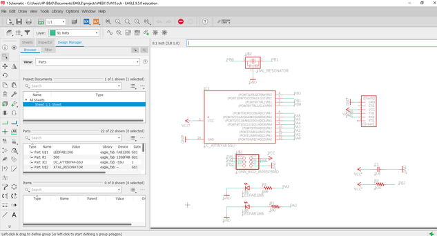
I have designed a new board using ATtiny44 and Two LED’s for this week assignment in order to connect it with the HC-05 bluetooth module, if you want to learn how to design a board check my Documentation on week07 using EAGLE
-
Here you can see that i have completed the schematics for my design on EAGLE and added all the parts i need :
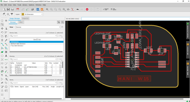
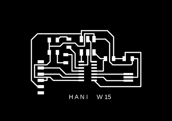
- Also here you can see the board design after i successfully routed all the connections :
- Now i exported my design and edited it using gimp in order to get the traces and the interior “outline” :
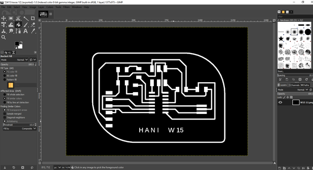
- Finally i have the design all ready so here is the traces and the interior “outline” :

- And here are the design files :
- Here is the rml files :
- Here is the SRM-20 machine cutting the traces :

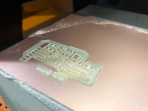
- And here is the machine cutting the interior :

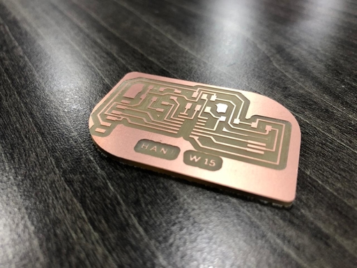
- Here is the final result :
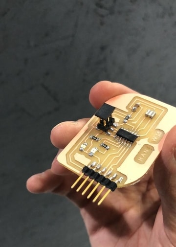
- Next i soldered the components which you can see in the table below :
| Description : | Reference : | Search : | library Name : | Quantity : |
|---|---|---|---|---|
| ATtiny44 | IC1 | tiny | UC_ATTINY44-SSU | 1 |
| Crystal 20MHz | XTAL1 | resonator | XTAL_RESONATOR | 1 |
| Header 3x2 ISP | J1 | ISP | CONN_03X2_AVRISPSMD | 1 |
| Header 1x6 FTDI | J2 | FTDI | CONN_06_FTDI-SMD-HEADER | 1 |
| Capacitor unpolarized 1uF | C1 | cap | CAP_UNPOLARIZEDFAB | 1 |
| Resistor 10kOhm | R1 | resistor | R1206FAB | 1 |
| Resistor 499Ohm | R2 | resistor | R1206FAB | 1 |
| Resistor 499Ohm | R3 | resistor | R1206FAB | 1 |
| Red LED | D1 | led | LEDFAB1206 | 1 |
| Blue LED | D2 | led | LEDFAB1206 | 1 |
Checking the board :
- Here i have checked my board in order to know if there is anything wrong with it by flashing the LED’s using this code :
void setup() {
  // initialize digital pin LED_BUILTIN as an output.
  pinMode(2, OUTPUT);
  pinMode(3, OUTPUT);
}

// the loop function runs over and over again forever
void loop() {
  digitalWrite(2, HIGH);   // turn the LED on (HIGH is the voltage level)
  delay(10);                       // wait for a second
  digitalWrite(2, LOW);    // turn the LED off by making the voltage LOW
  delay(10);                       // wait for a second
  digitalWrite(3, HIGH);   // turn the LED on (HIGH is the voltage level)
  delay(10);                       // wait for a second
  digitalWrite(3, LOW);    // turn the LED off by making the voltage LOW
  delay(10);
}
Connecting the ATtiny44 with the HC-05
-
Now is the final result to see if i have solved and fixed the problem and finished this week assignment or not .
-
Here i have connected the Bluetooth module to my board and Programmed it then i opened the bluetooth app nad started to send “1” and “0” and finally it worked and all of my work paid off : )
-
Here is a video and a picture showing the module connected and Controlling my board .
Hero shot of individual assignment :
- Here is the code that i have written :
 #include<SoftwareSerial.h>
 char state ;
 /* Create object named bt of the class SoftwareSerial */
 SoftwareSerial bt(0,1); /* (Rx,Tx) */

 void setup() {
   bt.begin(9600); /* Define baud rate for software serial communication */
   pinMode(2,OUTPUT);
   pinMode(3,OUTPUT);
 }

 void loop() {

     if (bt.available()) /* If data is available on serial port */
     {
      state= bt.read();


      if (state == '0'){
       digitalWrite (3, HIGH);
             digitalWrite (2, LOW);

      }
      if (state == '1'){
       digitalWrite (2, HIGH);
             digitalWrite (3, LOW);

      }
     }
 }
- And here is the code actually working :