10. Input devices
Assignments for week 9 :
-
This week we have a group assignment and an individual assignment .
-
The group assignment for this week is to probe an input device’s analog levels and digital signals .
-
The individual assignment for this week is to measure something: add a sensor to a microcontroller board that i have designed and read it .
The goal for this week is to design a board using the skills we have learned in week 7 after selecting the right sensor as an input and to read the datasheet for that sensor and then to cut it solder it and read it .
Files to download :
I have included all the files that you can download down below and here you can find them directly :
Group assignment :
For the group assignment this week we have to probe an input device’s analog levels and digital signals and to do that we have measured the level of a push button that my colleague aziz have done in its two states, normal and pressed.
- The push button (normally open) is connected to Vcc through 10kOhm resistor, so in its normal state the level will be 5 V (digitally high). When pressed the level will be 0 V (digitally low).
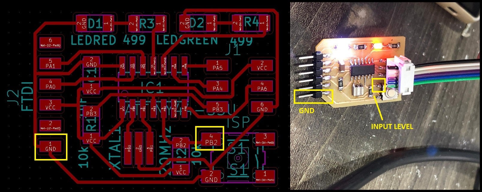
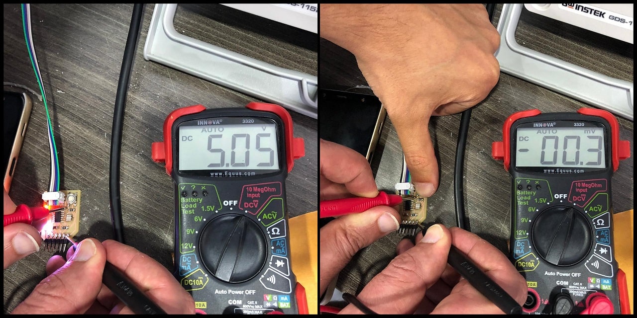
- Using the digital multimeter, in the normal state the measured value is 5.05 V (digitally 1 or high), and when pressed, the measured value is -0.3 mV (digitally 0 or low).
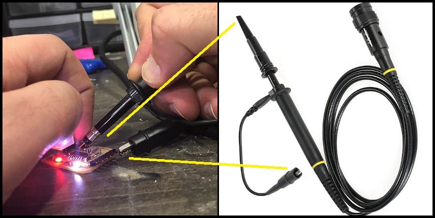
- We used oscilloscope to measure the same input signal. To connect the oscilloscope probe, connect the spring loaded end (hock or clamp) to GND and the pin head to test point, which is the push button signal.
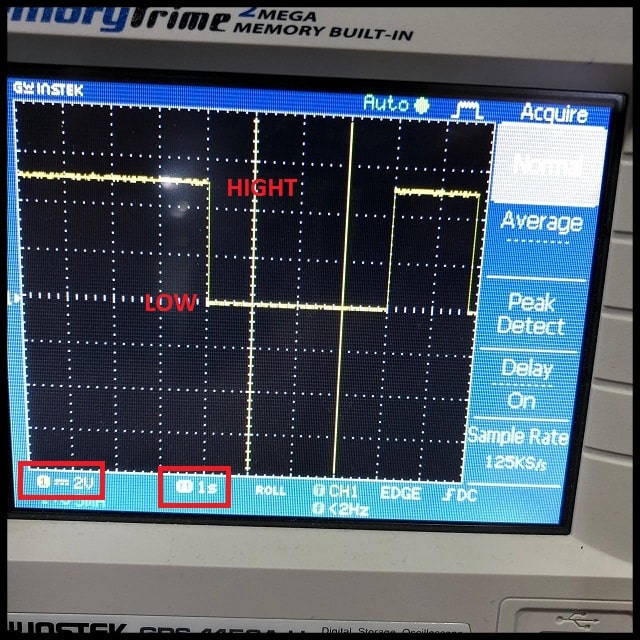
- Note that voltage scale is 2 V/division and time scale is 1 s/division. In the normal state, the signal height is 2.5 vertical divisions, which equals to 5V (2.5 divisions x 2 V/division). When the button is pressed, the level drop to fit over the zero line. The button had been pressed for 4 seconds (4 horizontal divisions x 1 s/division).
individual assignment :
For the individual assignment i have to added a sensor to a microcontroller board that i have to design and then read it, to start i want to decide which sensor i am going to use and after thinking i am going to use the microphone and the speaker for this week as a step closer to my final project and to do that i am going to design a board with a microphone as an input and an SD card reader then i will added a speaker as an output and all that will be designed on EAGLE, also i am going to use the ‘Hello board’ which i have programmed in the previous week to connect it with an ultrasonic sensor as an input 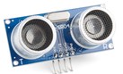 and then read program it that if it reads a specified distance the LED will be on, so lets start !!
designing my microphone board :
-
First i started to read about the microphone and i have found that i can use analog microphone and here is the Datasheet of the microphone i am going to use, also i have added LED to my board to see if the board is working before programming the microphone, this week for me was a proof that i am getting better and better in designing boards and using EAGLE way better than the first time and here is the process :
-
following neils board i have made my own design, also as i said before i have added LED to check if my board is working properly :
-
You can go back and check My documentation on week 7 to see every step on how to design a board using EAGLE .
-
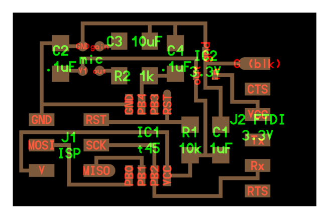
Here you can see that i have completed the schematics for my design on EAGLE and added all the parts i need :
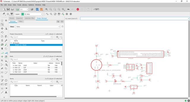
- Also here you can see the board design after i successfully routed all the connections :
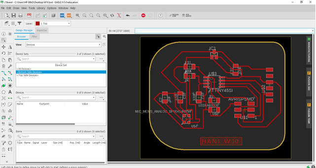
- Now i exported my design and edited it using gimp in order to get the traces and the interior “outline” :
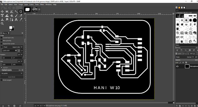
- Finally i have the design all ready so here is the traces and the interior “outline” :
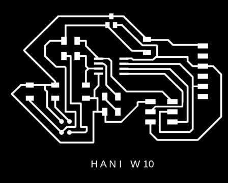

- And here are the design files :
- And here are the RML files :
Cutting the microphone board traces :
Cutting the microphone board outline :
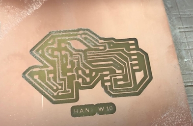
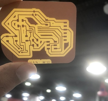
Microphone board :
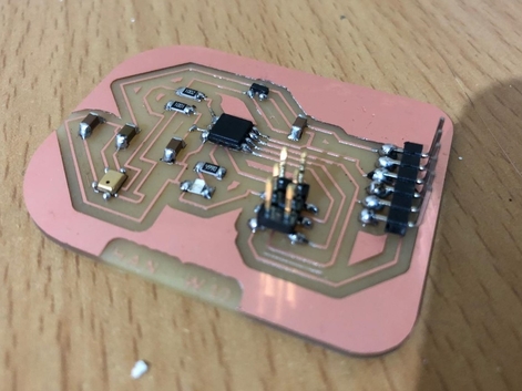
- Here is the final look for the board :
Ultrasonic sensor as an Input :
-
First i have to go back to read the ATtiny44 datasheet again in order to learn more and more about it also to read about the ultrasonic sensor and how it works .
-
Now after reading and learning about the ultrasonic here is what i came up with :
What is the ultrasonic works ?
-
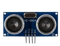
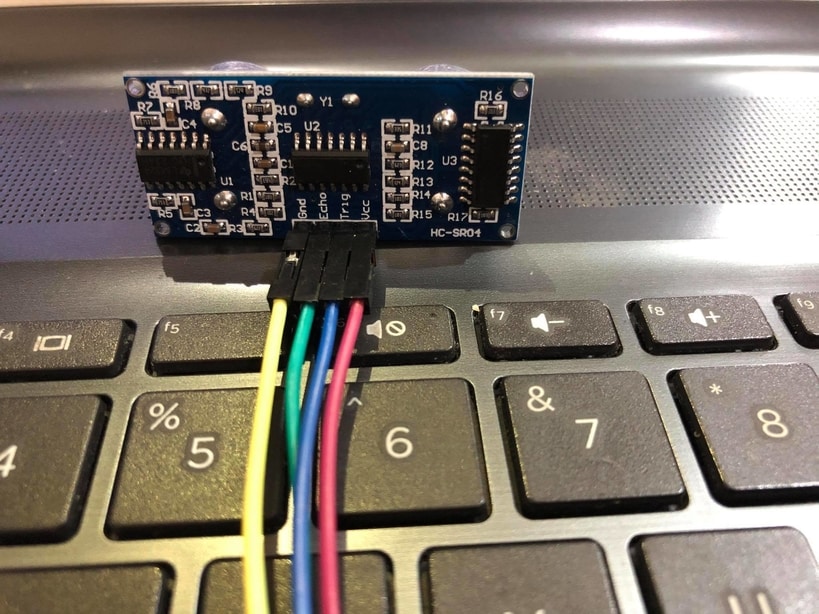
Ultrasonic sensor has 4 Pins, 1. VCC / 2. Trig / 3. Echo / 4.GND
-
The VCC stands for 5V Supply, Which powers the sensor, typically with +5V
- The Trig stand for Trigger Pulse Input,This pin has to be kept high for 10us to initialize measurement by sending Ultrasonic wave.
- The Echo stands for Echo Pulse Output,This pin goes high for a period of time which will be equal to the time taken for the Ultrasonic wave to return back to the sensor.
- The GND stands for 0V Ground, Which is connected to the Ground of the system.
The Ultrasonic sensor features :
-
Operating voltage: +5V
-
Theoretical Measuring Distance: 2cm to 450cm
-
Practical Measuring Distance: 2cm to 80cm
-
Accuracy: 3mm
-
Measuring angle covered: <15°
-
Operating Current: <15mA
-
Operating Frequency: 40Hz
How does the Ultrasonic sensor works ?
-
This particular sensor works with the simple high school formula that Distance = Speed × Time
-
The Ultrasonic transmitter transmits an ultrasonic wave at a frequency too high for humans to hear, this wave travels in air and when it gets objected by any material it gets reflected back toward the sensor this reflected wave is observed by the Ultrasonic receiver module, then the sensor calculate the distance based on the time required .
-
I have found out that radar and ultrasonic sensors can be used for some of the same purposes, sound-based sensors are readily available, they can be had for just a couple dollars in some cases and in certain situations, they may detect objects more effectively than radar.
Advantages of the Ultrasonic :
-
Ultrasonic sensor has a feature in which this particular sensor has no problem with the colour of the material they are sensing.
-
At 20°C (68°F), the speed of sound is 343 meters/second (1125 feet/second), but this varies depending on temperature and humidity.
-
Specially adapted ultrasonic sensors can also be used underwater. The speed of sound, however, is 4.3 times as fast in water as in air, so this calculation must be adjusted significantly.
Disadvantages of the Ultrasonic:
- The Ultrasonic sensor has a problem if the material that is being sensed absorbs sound or its being shaped in a way that it reflects the sound waves away from the receiver and by that the readings will be unreliable.
Programming :
-
I have used my Board which i have made on Week 6 and successfully programmed on Week 8 and here is the process :
-
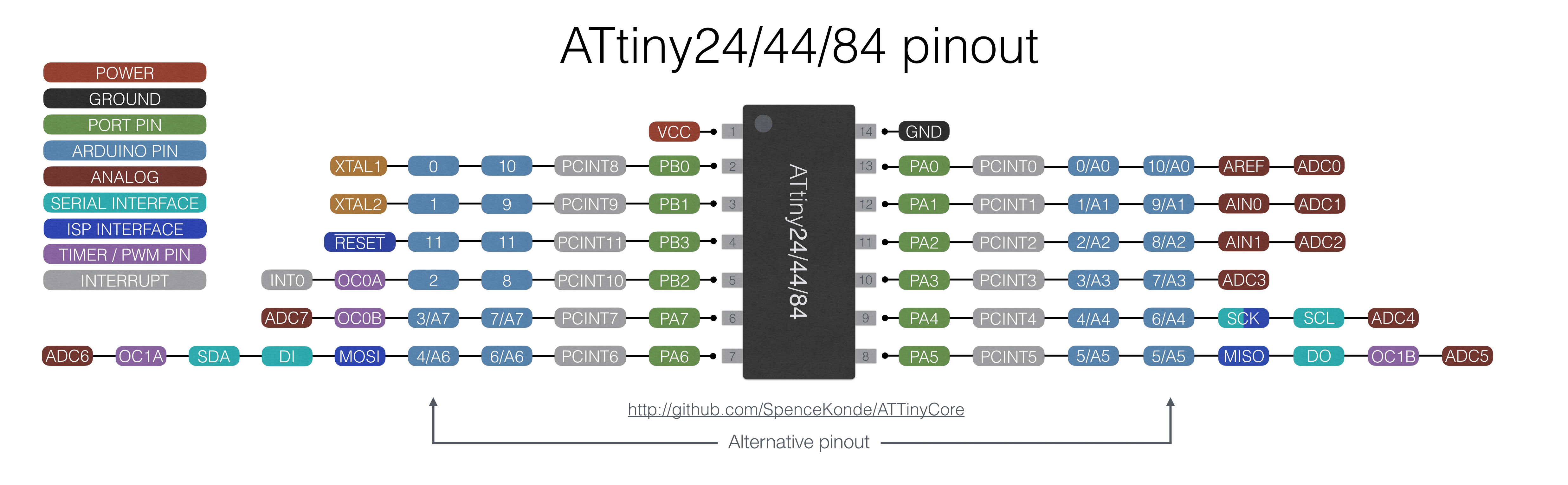
Lets remember the pin configurations of the ATtiny44 together :
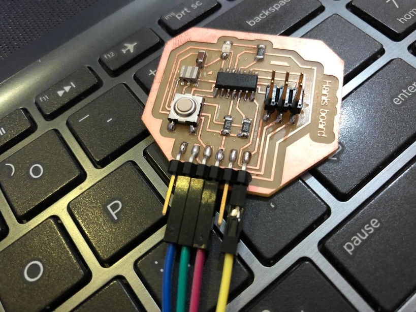
- Now the process is easy i just had to go back to the schematic of the design to see which pins i have to connect the ultrasonic sensor to and here is the schematic also Click here if you want to see the whole process of designing my board
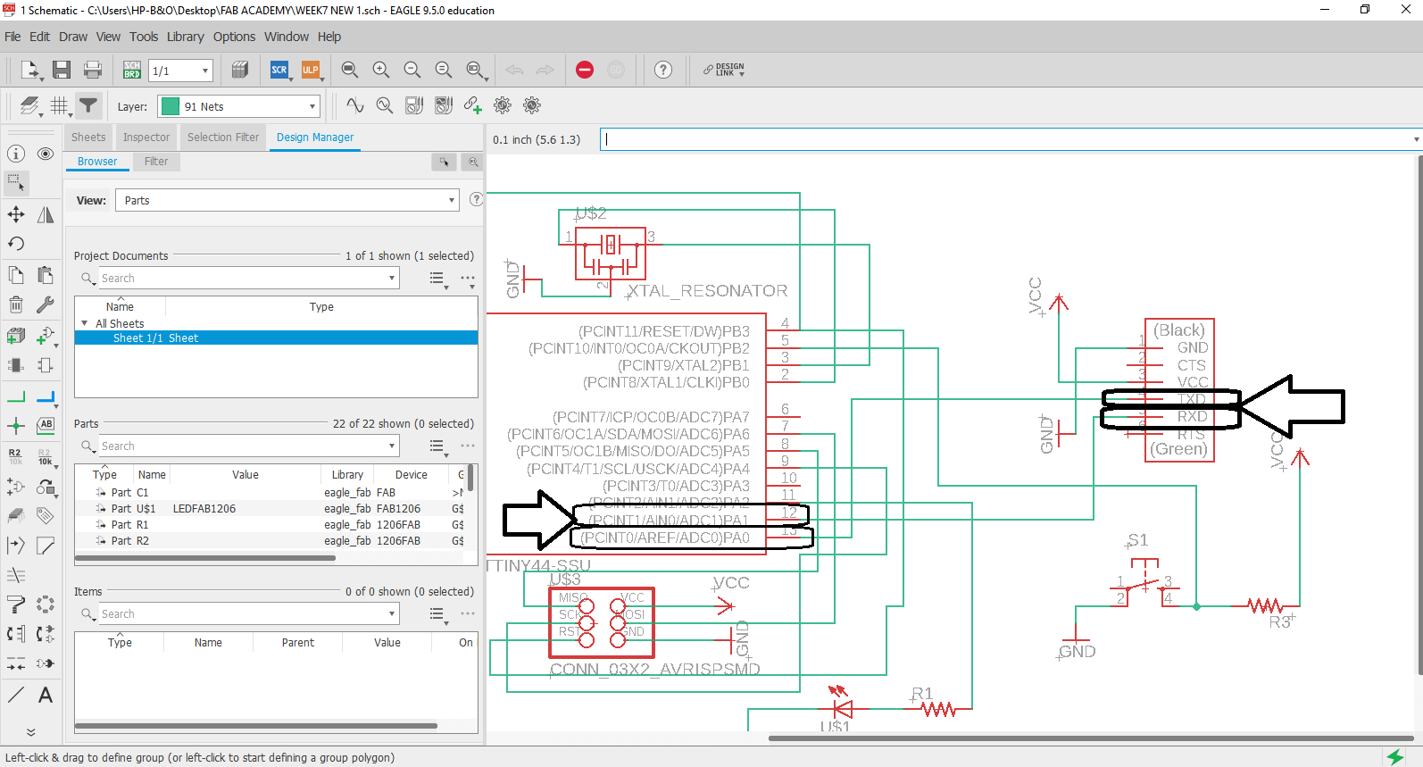
- As you can see i have to connect the Trig pin from the ultrasonic to PA1 on the board and the Echo pin from the ultrasonic to PA0 on the board then the GND pin from the ultrasonic to GND on the board and the VCC pin from the ultrasonic to VCC on the board like this :
Problem i faced and fixed :
- I have faced a problem with connecting my Programmer to my laptop although the LED was on but my board was not working, although i programmed it successfully on the previous week using the same programmer, so the problem was that the connecter between the programmer and my board was a little bit loose so i got it fixed and finally i programmed my board .
The hero shoot of the individual assignment :
-
Now after i have checked that i have the right connections i connected my programmer which i have made on Week 4 to the board and uploaded this code that i have written, i wanted to use everything i can because i dont have access to lab because of the current situation and quarantine.
-
Here is the code, this code is simple its just a condition that if this condition is broken the LED will be on:
// defines pins numbers on the ATtiny 44

const int trigPin = 1; // Connected to PA1
const int echoPin = 0; // Connected to PA0
const int ledPin = 2; // Connected to PA2

// defines variables that are used in this code !!

long duration;
int distance;


void setup() {
pinMode(trigPin, OUTPUT); // Sets the trigPin as an OUTPUT !
pinMode(echoPin, INPUT); // Sets the echoPin as an INPUT !
pinMode(ledPin, OUTPUT); // Sets the LED as an OUTPUT !

}

void loop() {
//  this to clears the trigPin

digitalWrite(trigPin, LOW);
delayMicroseconds(2);

// Sets the trigPin on HIGH state for 10 micro seconds

digitalWrite(trigPin, HIGH);
delayMicroseconds(10);
digitalWrite(trigPin, LOW);

// Reads the echoPin, returns the sound wave travel time in microseconds

duration = pulseIn(echoPin, HIGH);

//  this to calculate the distance !!

distance= duration*0.034/2;

// Here is the condition that if the distance is less or equal to 5 the LED will be on !!

if (distance <= 20){
 digitalWrite(ledPin, HIGH);
}
else{
 digitalWrite(ledPin, LOW);
}

}
- And here is the Board being programmed :
- And here is the ultrasonic working, i have read the data by turning the LED on :
Testing the microphone board :
- here i have uploaded a code just to see if the board is working :
Hero shot for the microphone board :
- i have uploaded Neils C file to my board then used Neils python file and here is the final result :