8. Computer controlled
Assignments for week 7 :
-
This week we have a group assignment and individual assignment .
-
The group assignment for this week is to test runout, alignment, speeds, feeds, and toolpaths for our machine that we have in the lab .
-
The individual assignment for this week is to make ( design + mill + assemble ) something big .
The goal for this week is to learn about the CNC machine, how the machine works, the differences between the milling bits, how to setup the machine, knowing the safety rules and to use the techniques that i have learned in the previous weeks in designing 2D and 3D objects .
Files to download :
I have included all the files that you can download down below and here you can find them directly :
Group assignment :
For the group assignment we have to test runout, alignment, speeds, feeds, and toolpaths for our machine that we have in the lab .
I have found this guide book so useful and in which i have taken some information from it and used it in my documentation you can check it by clicking here
- Here are some informations about the machine and how it works also what we can use it for :
Your ShopBot router is a low-cost, computer-numerically-controlled router (CNC Router). It is a workhorse of a workshop robot a Personal Robotic Tool. A ShopBot can perform precision, large-format, cutting, drilling, machining, and shaping in many materials and is controlled by a standard personal computer. A ShopBot offers you new ways to be productive and new paths to creativity. With your ShopBot you can mass produce a single item, or explore variations of plans, patterns, shapes and forms, and their reproduction in ways that would be difficult to attempt manually .
Safety rules :
- Before using the ShopBot you have to keep those safety rules in mind :
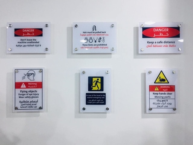
To ensure the full performance of this machine, be sure to observe the following important points. Failure to observe these may not only result in loss of performance, but may also cause malfunction or breakdown.
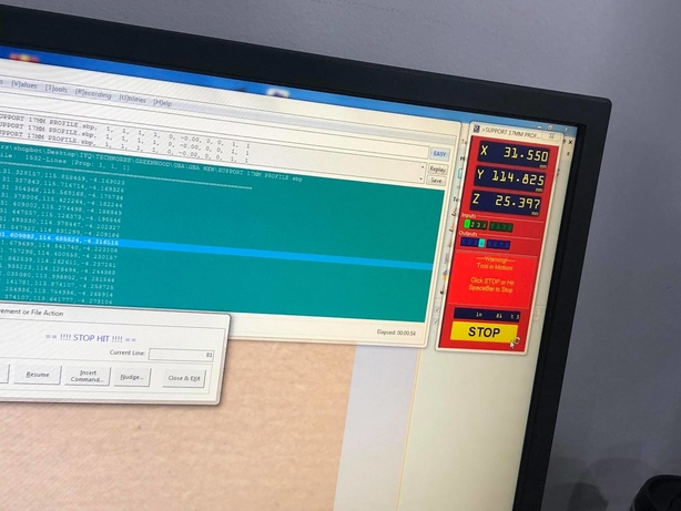
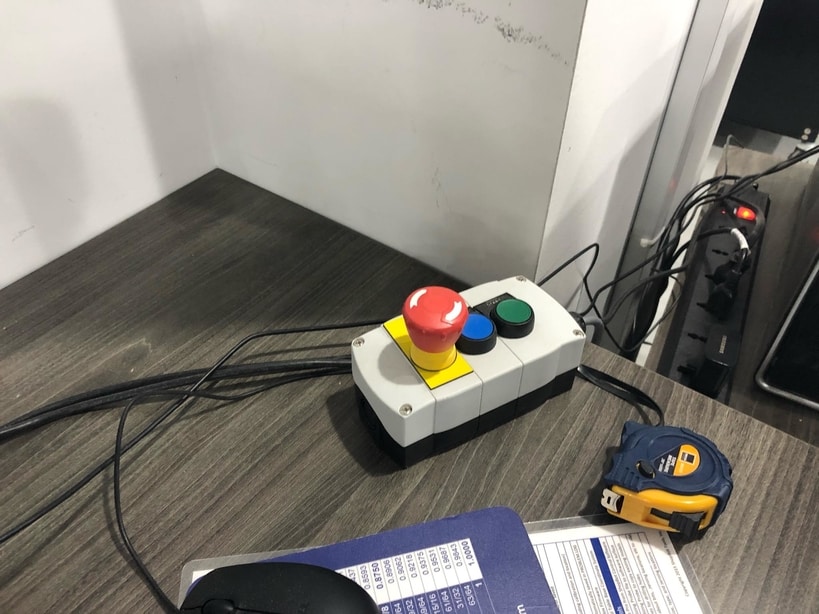
ALERT! HOW TO STOP!!
During tool operation the SPACEBAR on your computer keyboard becomes a Panic/Stop/Halt button. Hitting it will immediately stop the tool’s movement. Your ShopBot is also supplied with a STOP Button that you can place in a convenient location on your tool. Hitting this button will stop the tool’s movement. On a PRSalpha ShopBot or Buddy the STOP Button will also cut power to the spindle/router.
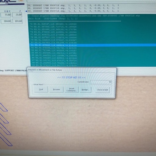
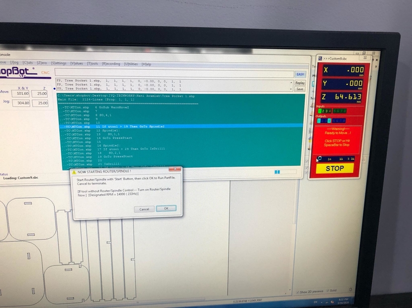
- When you click on stop or when you hit the space bar the machine will stop and this window will appear in which you can quit the job or resume it :
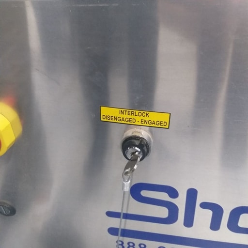
- Here is a look for the switch also :

TOOLS REQUIRE ATTENTION! Follow Safe Procedures!
Your ShopBot, in conjunction with a router or other power tool, is a flexible, tool-movement system that can reduce your woodworking risks by providing a method of cutting wood or other material without having to interact with the cutting device or the material during the cutting process. However, as with all power tools, care and attention are required to use a ShopBot safely. ShopBot Tools, Inc. assumes you will use this product safely and follow accepted safety precautions for woodworking and machining .
READ THESE SAFETY INSTRUCTIONS :
-
PRACTICE Practice operating your ShopBot tool with your computer and the ShopBot Control Software BEFORE activating the router or spindle .
-
PROTECT Turn OFF your router or other power tool before loading or positioning a workpiece or adjusting the position of the tool. Do not change router bits or other cutters without first unplugging the power tool or having a positive system to make sure the power tool is not accidentally activated. It is your responsibility to use it safely .
-
HOLD-DOWN Never attempt to cut wood or other material without first ensuring that the work is firmly secured to the work surface. Power cutting tools always carry the risk that work material or broken cutters will be sent flying towards the operator or others in the area. A tool like ShopBot allows you to work with the workpiece secured and thus greatly reduces this risk. It also allows the operator to be away from the cutting and protected. However, YOU must take the steps to secure the workpiece and protect the operator. Note that not only must the full starting piece be secured, but you need to attend to the attachment and security of any pieces that will become cutouts or cutoffs during the cutting or machining process. Stand clear of the tool when it is in operation and protected from debris, parts, or broken cutters that might fly out during operation. Never attempt to push material by hand through a moving bit or to interact with the tool while it is running .
-
AWAKE Never operate the tool when you are fatigued .
-
EYES & EARS Always protect your eyes and ears when operating your ShopBot .
-
ATTEND NEVER leave the tool unattended while it is running. A cutting error or workpiece slippage that the tool cannot detect might occur. Some person unknowledgeable about tool operation might approach and start the tool. Or some other unexpected event might occur .
-
GUARD Always position the dust skirt correctly to guard against flying particles .
-
TO STOP During a cutting or motion process, the SPACEBAR on the computer keyboard is a Panic/Stop/Halt button. Hitting the bar will stop the tool’s movement. Your ShopBot PRSalpha also has a remote STOP Button that interrupts power to the stepper motors and the spindle or router after it is pushed. You should locate the STOP Button convenient to your tool and workstation. Note: For PRS systems the power tool is operated independently of your ShopBot, it must be turned off separately .
-
POSITION The safest location for you during the operation of the tool is within easy reach of the computer keyboard or STOP Button and well away from the path of the tool. Because bits can break and fly loose during cutting – stand behind a protective screen .
-
BE SMART Most importantly, never place yourself at risk during a cutting or machining process by placing any part of you near the cutting path or by attempting to move or adjust the workpiece or active tool. SHOPBOT IS A ROBOT, BUT YOU ACTIVATE ITS MOVEMENT AND YOU TURN ON AND OFF ITS POWERED CUTTING-TOOL .
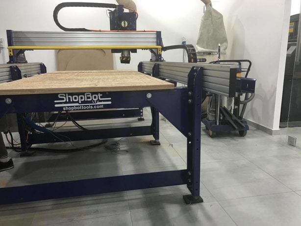
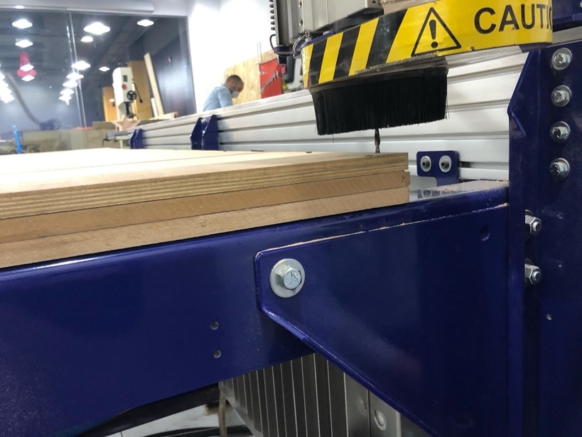
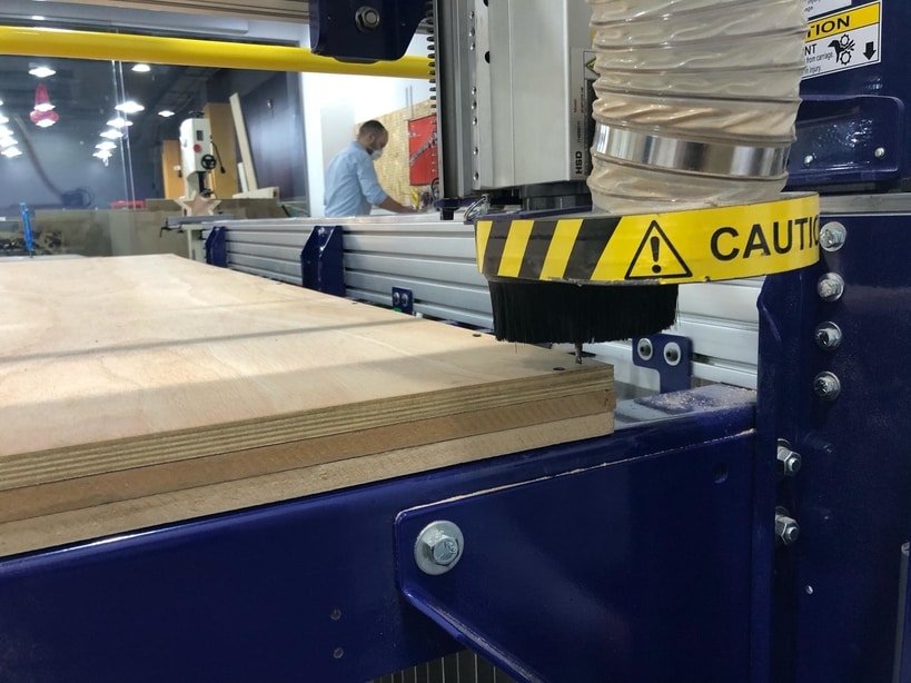
Here is the machine “ShopBot” :
- Here is a look for the machine that we have in our lab :
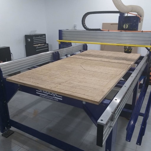
- Here you can see the sacrifice bed :
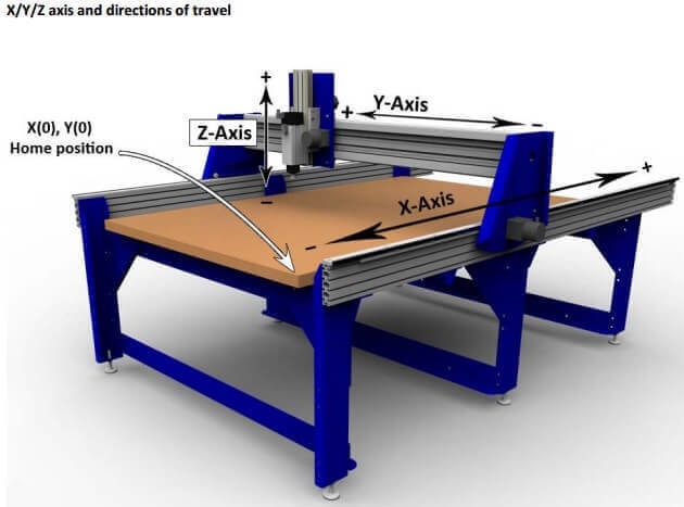
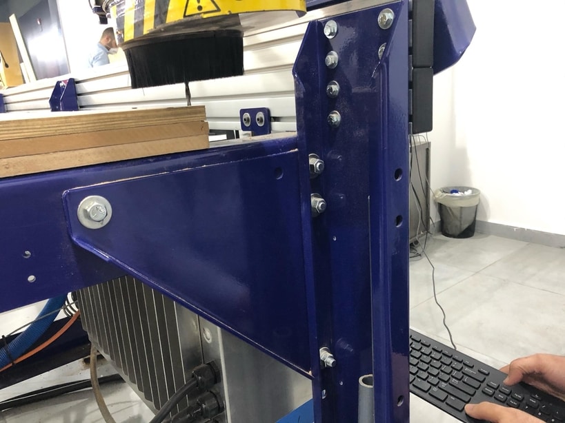
- Here the axis of how the machine moves :
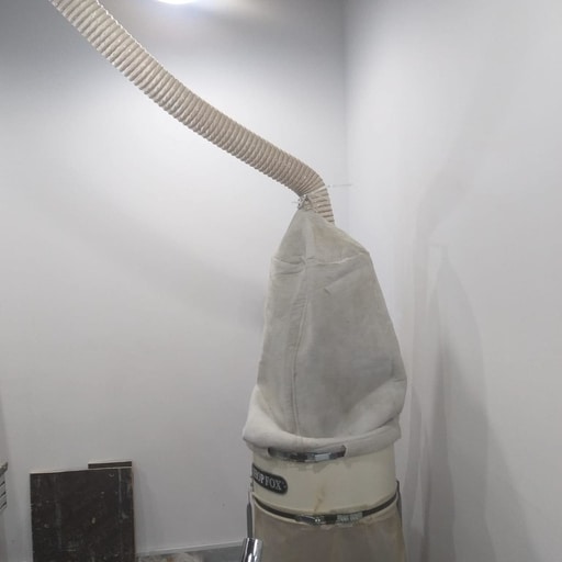
- Here is the vacuum which is connected directly to the machine :
Speed and feed rate :
My colleague Aziz has showed us the Cutting Data Recommendations that is provided by the tool manufacturer to calculate the feed rate “Feed rate the speed at which the cutter engages the part and is typically measured in units/minute”. me and my colleagues used the data provided for MDF which is similar to plywood Recommendations.
-
Downcut bit series: 57-200
-
Upcut bit series: 52-200
-
Bit diameter: 1/4”
-
Depth of cut: 1 x 1/4”
-
Using these inputs on the chart we find the recommended “Chip Load” is equal to 0.006”-0.008 inches/flue”. For this job we set the spindle speed to 14,000 RPM (max is 18,000 RPM).
-
Using the formula Chip Load = Feed Rate / (RPM x # of Flutes), where chip load in inches per flute, feed rate in inches per minute and RPM in revolution per minute, we can find that feed rate is equal to (168 - 224) inches/minute or (2.8 - 3.7) inches/second. Any value in the range would do fine
-
You can also use Fablab Speed and Feeds Calculator in order to calculate the speed and the feed rate .
What is Vcarve-pro ?
-
VCarve Pro provides a powerful but intuitive software solution for creating and cutting parts on a CNC Router. VCarve Pro gives you the power to produce complex 2D patterns with profile, pocket, drill and inlay toolpaths, plus gives you the ability to create designs with v-carving textures as well as import and machine unlimited Vectric 3D clipart or single model files. The ‘Pro’ edition gives you unlimited job and toolpath size, true shape nesting & job set-up sheets, ideally suited to a production environment.
-
Here our CNC specialist gave us some instructions about using “Vcarve-pro” and how to differentiate between the milling bits “Up-cut milling tool”, “Down-cut milling tool” and the “Up Down cut milling tool” :
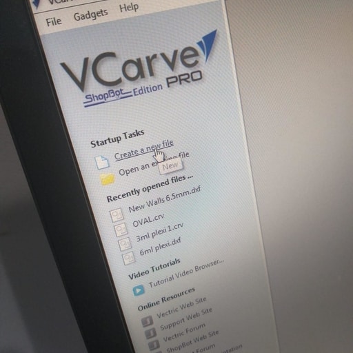
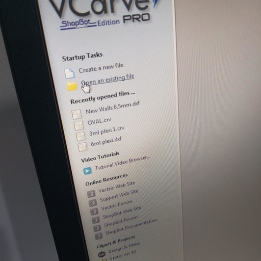
First we open the software and this window will appear, we can make a new file or open an existing file and in our case we have open an existing file in order to see the difference between the milling bits and how to set up the machine properly :
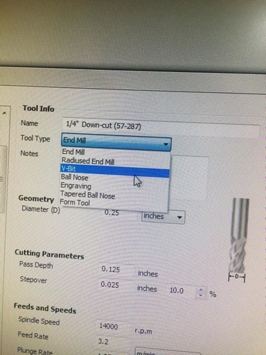
Second after choosing the file we want to cut, we choose the milling bit needed for this job like this :
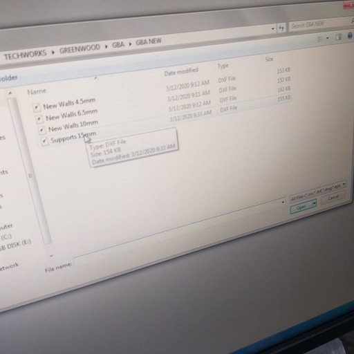
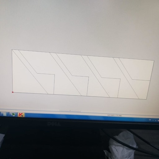
Here is the job that we are going to do the test on :
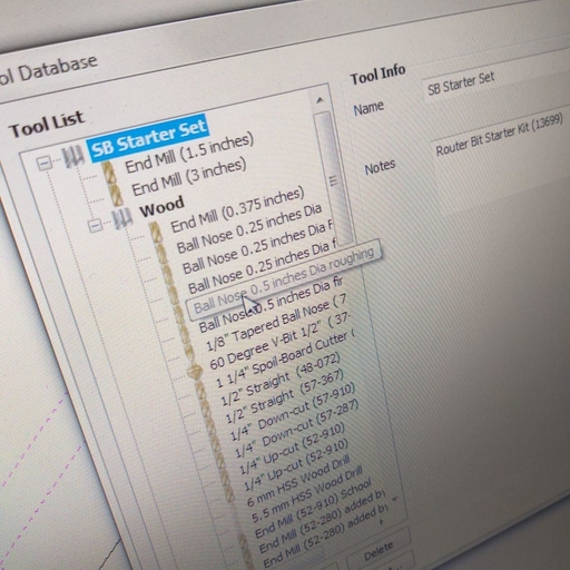
Here we have chosen the “1/4 Down-cut” milling bit :
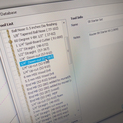
From here you can see that there are different tool types
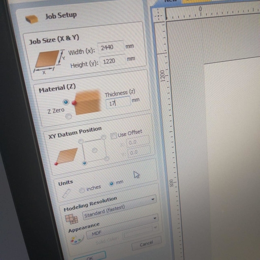
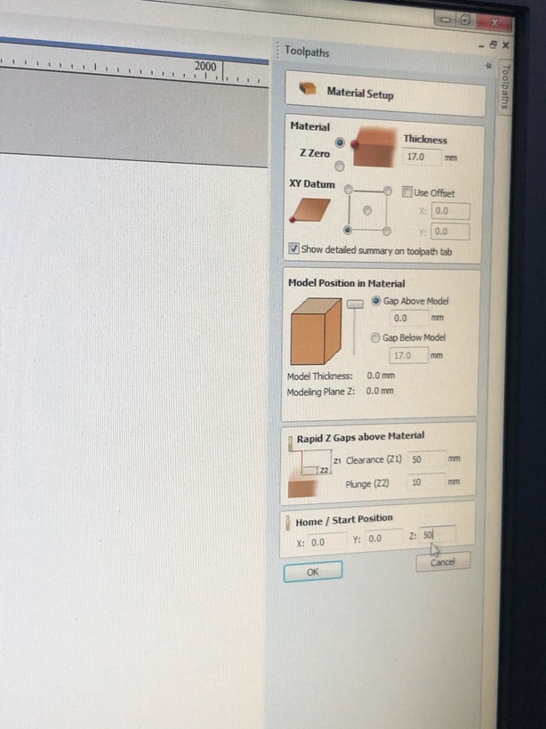
And after choosing the milling bit you have to set The Job Setup
which form is displayed whenever a new job is being created, or when the size and position of an existing job is edited.
there are different job types like single sided or double sided
Select Single Sided if your design only requires the material to be cut from one side. This is the simplest type of job to design and machine.
If your design requires you to cut both sides of your material then VCarve Pro also allows you to visualise and manage the creation and cutting process of both sides of your design within a single project file. Select Double Sided if you need this additional functionality.
Also you to check the Z Zero Position which indicates whether the tip of the tool is set off the surface of the material (as shown in the diagram) or off the bed / table of the machine for Z = 0.0.
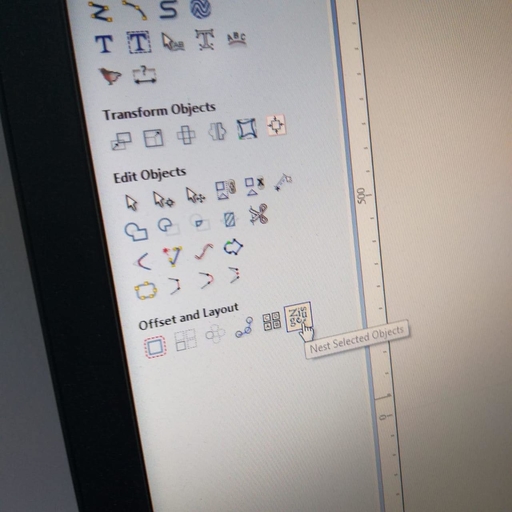
Here you can see that this symbol “Nest selected objects” helps you to reorder the design or the job you want to cut in a way that saves material :
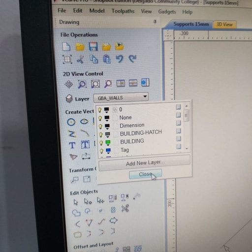
Here you can see that also in this software there are layers in which you can hide and show, but be careful while choosing the layers because after all its a machine and it will translate what you command here to do on the job, as you can see there are different layers :
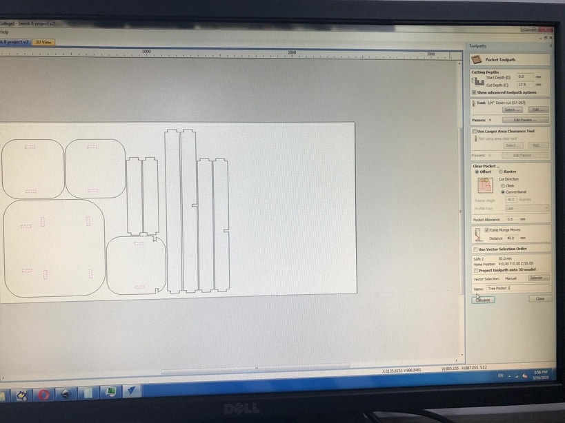
Toolpaths :
- From here you can choose whether you want a “Pocket toolpath” or a “Profile toolpath” and the difference between those toolpaths is :
“Pocket toolpath”
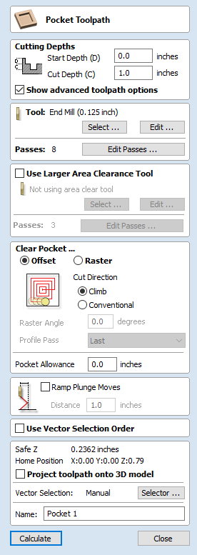
you can chose this option from this symbol, This option opens the Pocket Toolpath form for machining 2D pockets. These toolpaths automatically compensate for the tool geometry - both diameter and angle. 
Cutting Depths :
Start Depth (D) :
Specifies the depth at which the pocket toolpath is calculated. When cutting directly into the surface of a job the Start Depth will usually be 0. If machining into the bottom of an existing pocket or stepped region, the depth of the pocket / step must be entered.
Cut Depth (C) : The depth of the toolpath relative to the Start Depth.
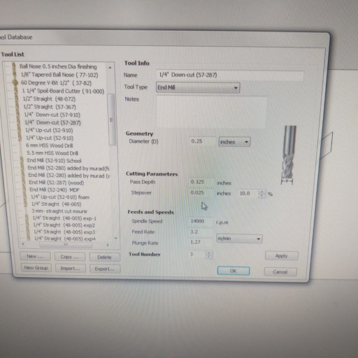
Tool :
Clicking the “Select” button opens the Tool Database : “which is used to make cutter management and selection very quick and easy, and reduces the possibility of programming jobs with incorrect cut depths and speeds and feeds. The Tool Database is accessed from the Select… button every time you create a new toolpath and allows pre-defined tools and settings (speeds, feeds, stepover etc.) to be selected from a list.” from which the required tool can be selected.
Clicking the “Edit” button opens the Edit Tool form which allows the cutting parameters for the selected tool to be modified, without changing the master information in the database.
Specify Pass Depths :
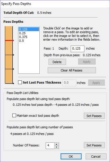
The Pass Depths section at the top of the form shows a list of the current pass depths. The relative spacing of the passes is indicated in the diagram next to the list. Left click on a depth value in the list, or a depth line on the diagram, to select it. The currently selected pass is highlighted in red on the diagram.
To edit the depth of the selected pass, change the value in the Depth edit box and clickApply.
The Delete button will delete the selected pass.
The Clear All Passes button will delete all the passes.
To add a new pass, double left click at the approximate location in the passes diagram that you wish to add the pass. A new pass will be added and automatically selected. Edit the precise Depth value if required and then click Apply.
The Set Last Pass Thickness option will enable an edit box where you can specify the last pass in terms of the remaining thickness of material you wish to cut with the last pass (instead of in terms of its depth). This is often a more intuitive way to specify this value.
Clear Pocket
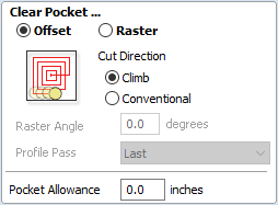
There are two choices of the type of fill pattern that will be used to clear away the area to be machined with the Pocket Toolpath, Offset and Raster.
 Offset
Calculates an offset area clearance fill pattern to machine inside the selected vector(s). Options for Cut Direction to be either: Climb (CCW) cutting direction Conventional (CW) cutting direction.
Offset
Calculates an offset area clearance fill pattern to machine inside the selected vector(s). Options for Cut Direction to be either: Climb (CCW) cutting direction Conventional (CW) cutting direction.
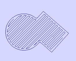
 Raster
Calculates a Raster based area clearance fill pattern to machine inside the selected vector(s). Cut Direction for the final pass to be either:
Raster
Calculates a Raster based area clearance fill pattern to machine inside the selected vector(s). Cut Direction for the final pass to be either:
Clear Pocket - Offset Strategy

Clear Pocket - Raster Strategy
Profile Toolpath
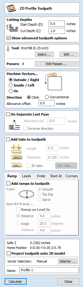
Profile Machining is used to cut around or along a vector. Options provide the flexibility for cutting shapes out with optional Tabs / bridges plus an Allowance over/undercut to ensure perfect edge quality. 
Cutting Depths :
Start Depth (D) :
Specifies the depth at which the Profile toolpath is calculated. When cutting directly into the surface of a job the Start Depth will usually be 0. If machining into the bottom of an existing pocket or stepped region, the depth of the pocket / step must be entered. Cut Depth (C) :
The depth of the profile toolpath relative to the Start Depth.
Tool :
Clicking the Select button opens the Tool Database from which the required tool can be selected. Clicking the Edit button opens the Edit Tool form which allows the cutting parameters for the selected tool to be modified, without changing the master information in the database. Hovering the mouse cursor over the tool name will display a tool tip indicating where in the Tool Database the tool was selected from.
Machine Vectors :
There are 3 options to choose from to determine how the tool is positioned relative to the selected vectors/s.
Outside

Calculates a profile toolpath around the Outside of the selected vectors, with options for the cut direction to be either,
Climb (CW) cutting direction or Conventional (CCW) cutting direction
Inside

Calculates a profile toolpath around the Inside of the selected vectors, with options for the cut direction to be either;
Climb (CCW) cutting direction or Conventional (CW) cutting direction
On

Calculates a profile toolpath around the On the selected vectors, with options for the cut direction to be either,
Climb (CW) cutting direction or Conventional (CCW) cutting direction
Tabs (Bridges)
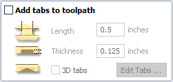
Tabs Group Tabs are added to open and closed vector shapes to hold parts in place when cutting them out of material.
Add tabs to toolpath
Checking ✓ the Add tabs option will activate tab creation for this toolpath. The Length and Thickness specify the size of each tab. Checking ✓ the Create 3D Tabs option will create 3D Tabs, the difference between this and 2D Tabs is described below.
Create 3D Tabs
When this option is selected the tab will be triangular in section. This is shape is created as the cutter ramps up to the specified Tab Thickness then down the other side. The 3D Tabs will often allow the machine to run quicker and smoother because it does not have to stop to move in Z at the start and end of each tab.
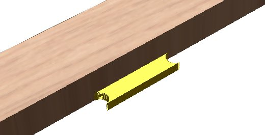
Here you can see the difference between 3D tabs and 2D tabs :
3D TAB
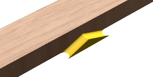
2D TAB
Thats almost everything you have to know as a basic if you are going to cut and prepare the job by yourself
Here you can see a “pocket design” :
Here you can see a profile design :
Also you can watch this video to see the difference between the pocket and profile
milling bits :
Down cut milling tool: Those are usually used to create a soft upper layer, its mainly used to only cut the first 5-7 mm on the plywood and then for a better finish to replace it with a upper cut. For down cut the speed rate must be low and the depth cut should also be decreased.
Up-cut milling tool: This bit is usually used to create a smooth surface at the end of the wood.
Feed rate: how fast the bit moves across the wood
See the difference between the milling bits
set up the machine :
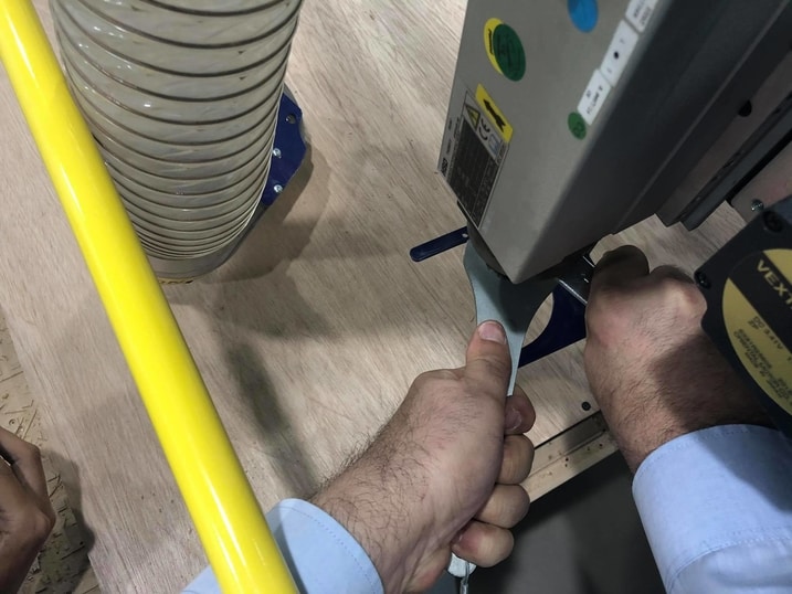
- First we have to change the milling bit and here is the process :
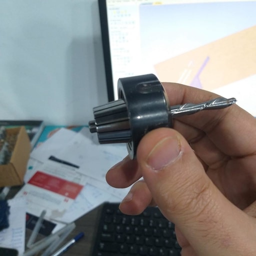
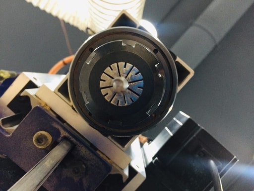
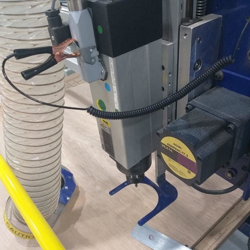
- Second we make sure that the milling bit placed correctly and we can check that by seeing that the milling bit is placed correctly like this :
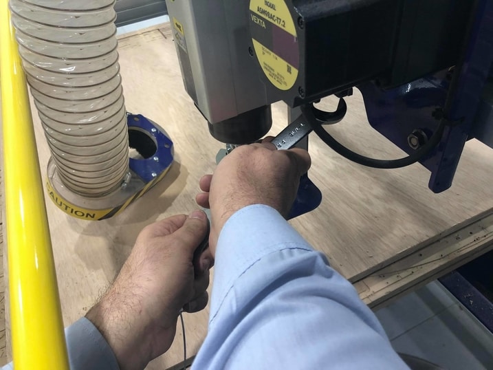
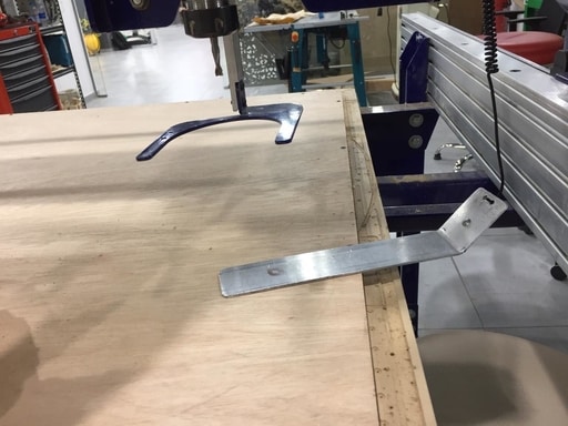
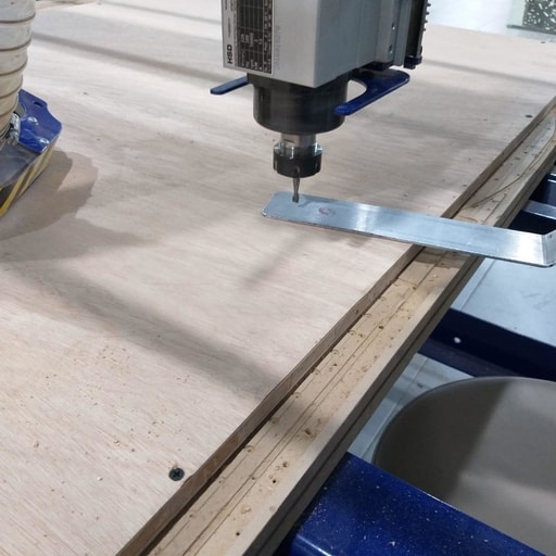
- Now we have to level the machine and that how to do it :
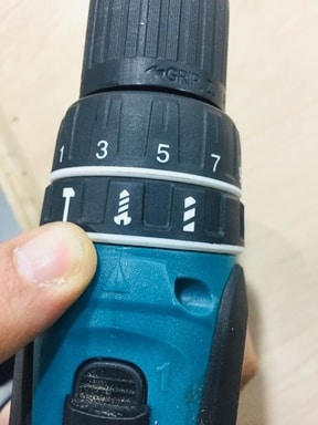
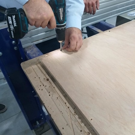
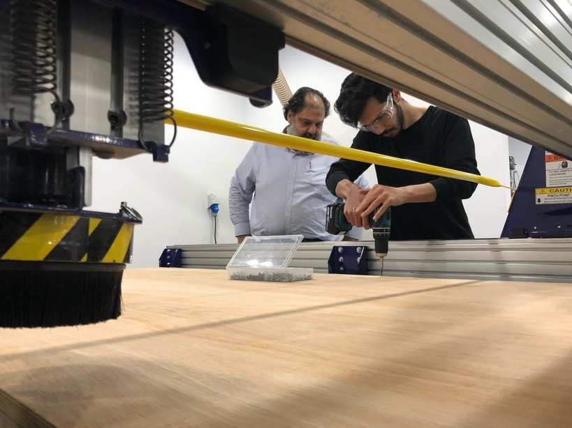
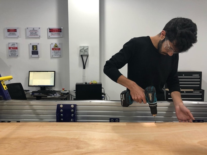
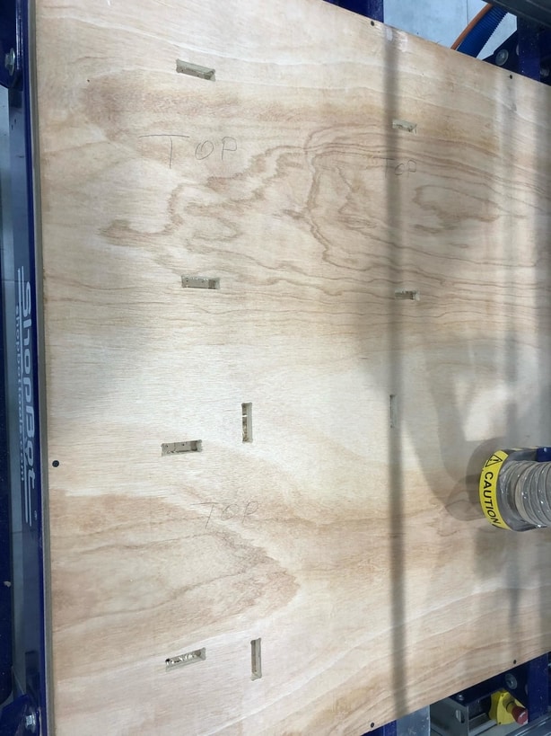
- Here we have to make sure that the board we are cutting is placed and 100% fixed and to do that we fix it by screws using this drill like this :
Now we are ready to cut :
this is the final result :
-
Here you can see the difference between the up-cut milling bit and the down-cut milling bit :
-
This down-cut
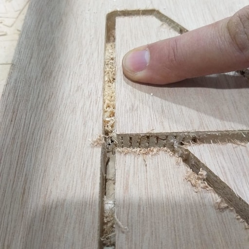
- This is up-cut :
And that is all for our group assignment.
The individual assignment :
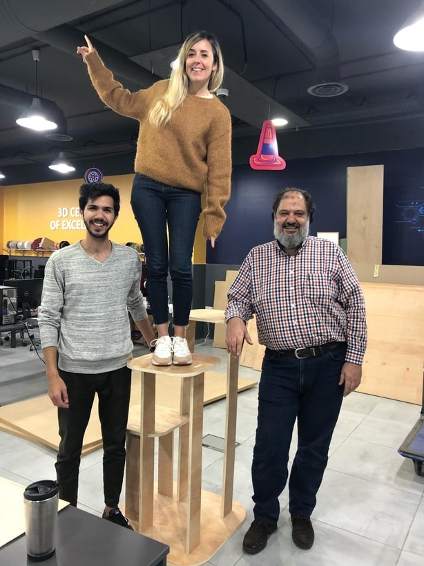
For the individual assignment this week we have to make ( design + mill + assemble ) something big .
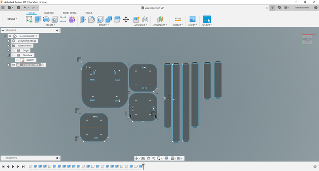
And to do that i have decided to design a tree cat house using fusion 360 and here is the process :
- Here is the design :
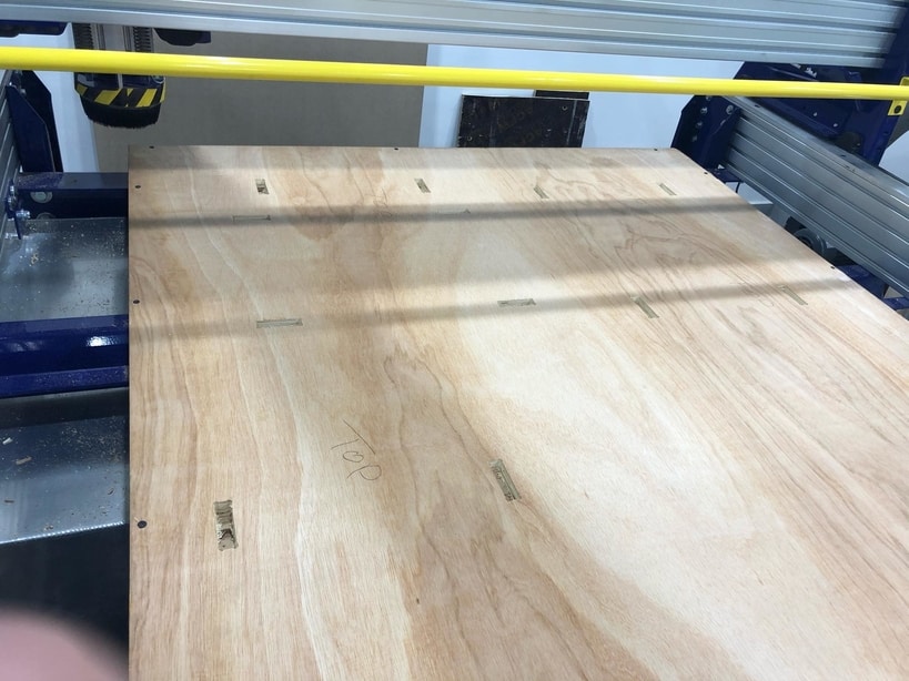
- Here i have placed the board on the machines bed
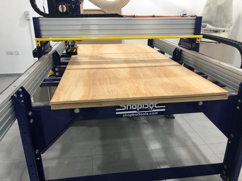
- Here you can see that i have fixed the board to bed using screws :
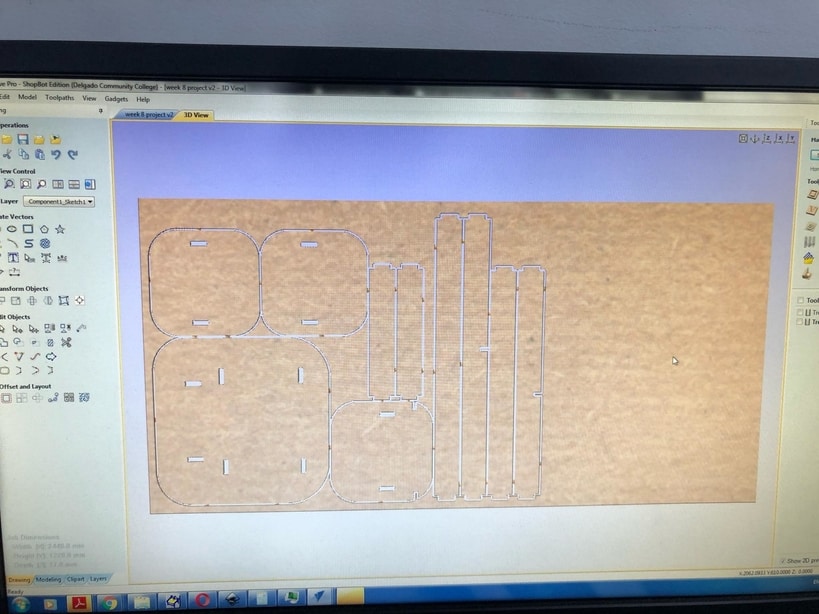
- Here i have put the design on Vcarve in order to set up the machine :
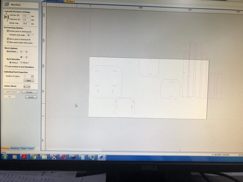
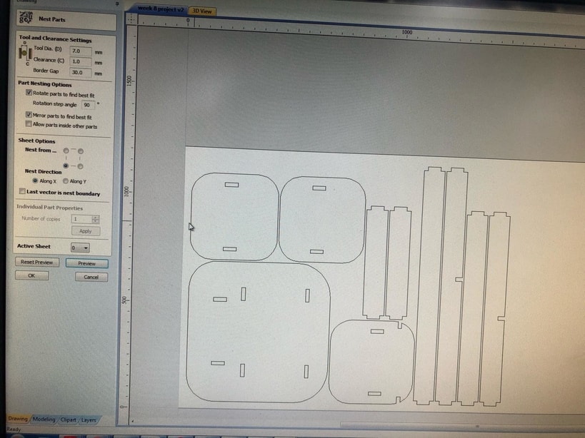
- Here you can see that the design is not nested so in order to nest the design and save material i have clicked on the symbol nest and here is the result :
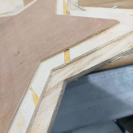
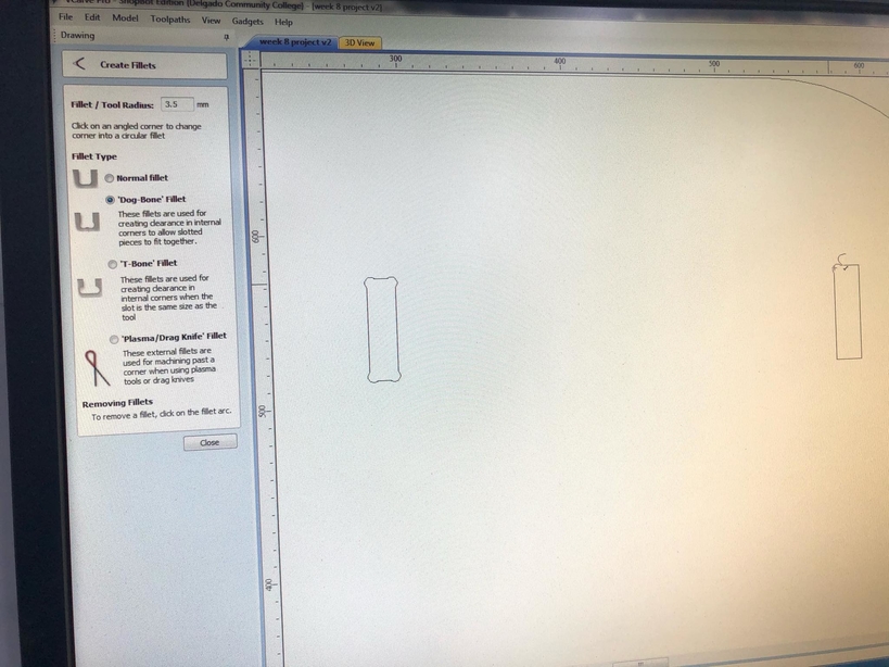
- Here i have added a “Dog-bone” Fillets in order to insert the joints easier, also here i have added some tabs to hold the board and the pieces while cutting :
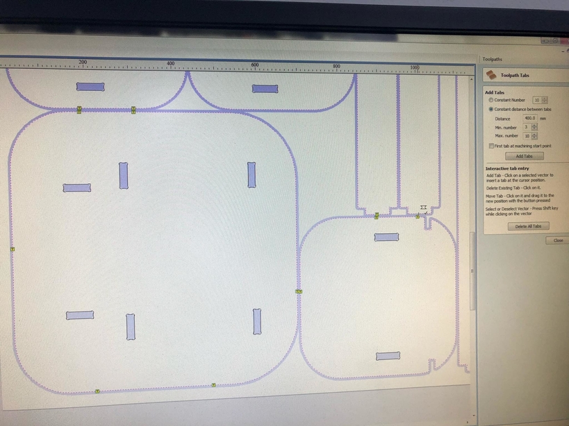
- Now we generate the toolpaths and i have used the “Pocket toolpath” for the joints and the “profile toolpath” for the pieces :
- Then i have made a simulation for the design in order to see how the machine is going to cut the design :
- Here me and our CNC specialist are setting the milling bit on the zero axis where the machine is going to start cutting :
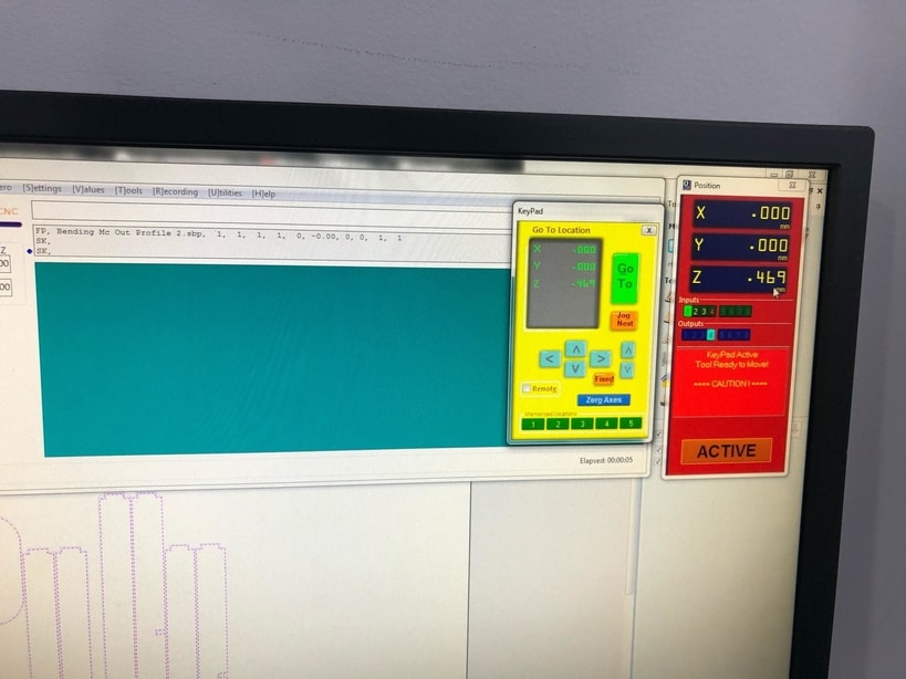
- Now we are ready to cut, so i have clicked on the green button on order to make the spindle start moving in the air to warm up and then started to cut :
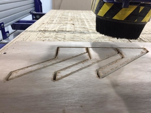
- I have ordered the machine to cut the pockets first and here is a look :
- Here the machine finished the pockets :
- Here the machine is cutting the profile :
- Here you can see the machine cutting and almost finished the design :
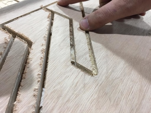
- Now after the machine finished cutting i have removed the taps and then the screws and
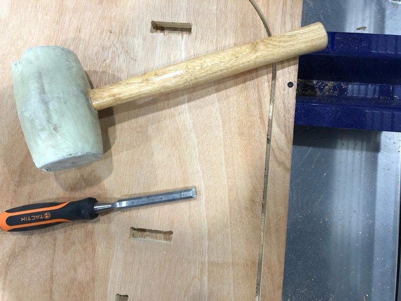
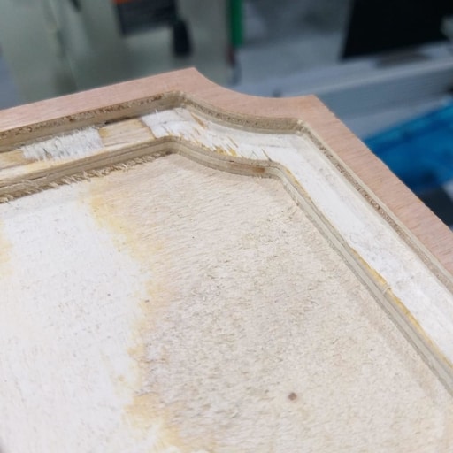
- Here you can see that i have started to clean the pieces one by one :
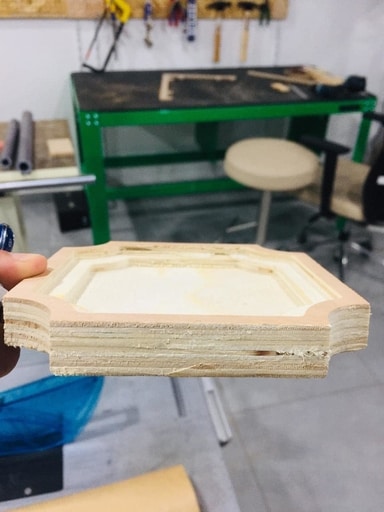
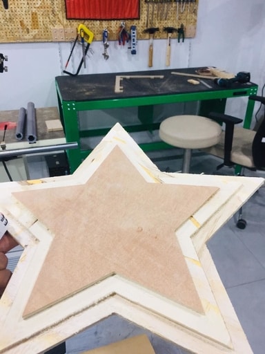
- After cleaning the pieces i have started to assemble the parts :
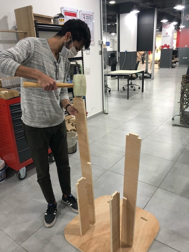
The hero shot of the individual assignment :