Final project documentation :
Laser cat
Automatic cat food dispenser
 +
+  +
+  +
+ 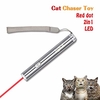
my final project will be an automatic cat food dispenser, for this project I will design a case which holds the food in it and the plate will be wood because some cats are allergic to plastic in general , the food will be served as portions so when the plate is empty the sensor which can be ( weight sensor or ultrasonic sensor) will measure the foods weight if it’s a weight sensor or the foods height in the food holder if its ultrasonic sensor, if the foods weight or height is less than the required portion weight or height a signal will be send to the microprocessor and the plate will be refiled again, after 15 to 20 minutes a laser will turn on and move in several directions so the cat can play and don’t get bored, also when its time for the cat to eat and the portion is served a speaker will turn on to alert the cat that its time to eat and the sound that will alert the cat will be the owners voice, on the other hand the cat food dispenser will be connected to a mobile application to warn the cat owner if the food is empty .
Here is a simple sketch of the final project
inspiration :
i was inspired by Toni’s final project he also did a cat food dispenser Click here to see his final project
Final project Plan
| Designing | Week 2 | in this week i did the first point in the process and its to design a food dispenser and a case for the final project | time needed : 4 days | Here is the result |
|---|---|---|---|---|
| Laser cutting | Week 3 | in this week i have cut the case design | time needed : 1 day | Here is the result |
| 3D printing | Week 5 | in this week i have 3D printed the food dispenser and measured the food portions | time needed : 3 days | Here is the result |
| Electronics design “Input” | Week 9 | in this week i have designed a board for my microphone | time needed : 3 days | Here is the result |
| Electronics design “Output” | Week 11 | in this week i have designed a board for my stepper motor, servo motor and the speaker | time needed : 4 days | Here is the result |
1. The process :
-
the food holder will be designed using fusion 360 and 3D printed using ultimaker3.
-
the case will be designed on fusion 360 and it will be cut by laser cut .
- the food will be served as portions and to do that i will design a food dispense mechanism using fusion 360 and it will be printed using zortrax and it will be connected to a stepper motor.
- the laser will be connected to a servo motor which will turn on after 20 minutes from serving the food to the cat.
- the speaker will be connected to the microprocessor and the voice of the owner will be recorded and saved .
- the weight sensor will be connected to the plate and the microprocessor so when its empty the step motor that is connected to the food dispense machine responds and serve the food.
- all the electronics will be designed using EAGLE software and cut by monoFab SRM-20.
The Final outcome will help cat owners if they had to leave their cats alone for a long period of time !!
2. List of some parts and components that i need to make this project:
| Input | Output | Power supply | Materials | link for each component | Machines used |
|---|---|---|---|---|---|
| 1 x Weight sensor | 1 x Stepper motor | 1 x 12VDC 74mA for the stepper motor | Plywood | for the weight sensor | CNC for cutting the Plywood |
| 1 x HX711 | 1 x speaker “greeting card” | 1 x 9V for the servo motor | Acrylic | for the stepper motor | Laser cutter and vinyl cutter for the acrylic and the stickers |
| Microphone | 1 x Servo motor | 1 x 5V for the board | PLA | for the 12V Power supply | ultimaker3 for 3D printing |
| SD card reader | 2 x Laser | -------- | --------- | for the greeting card | Monofab SRM-20 for milling the Boards |
Techniques :
1. 2D and 3D Modelling :
Final project designs :
Design File : Click here to see the design
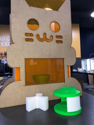
This is the first idea for the case :

- In this photo you can see my first idea for the final project case, i wanted to 3D print this case design but i realized that it will be a waste of materials to 3D print such a big case, so i decided to think and design another case in which i can cut by the laser cutter .
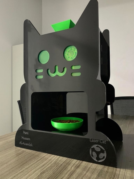
The final idea for the final project case design :
-
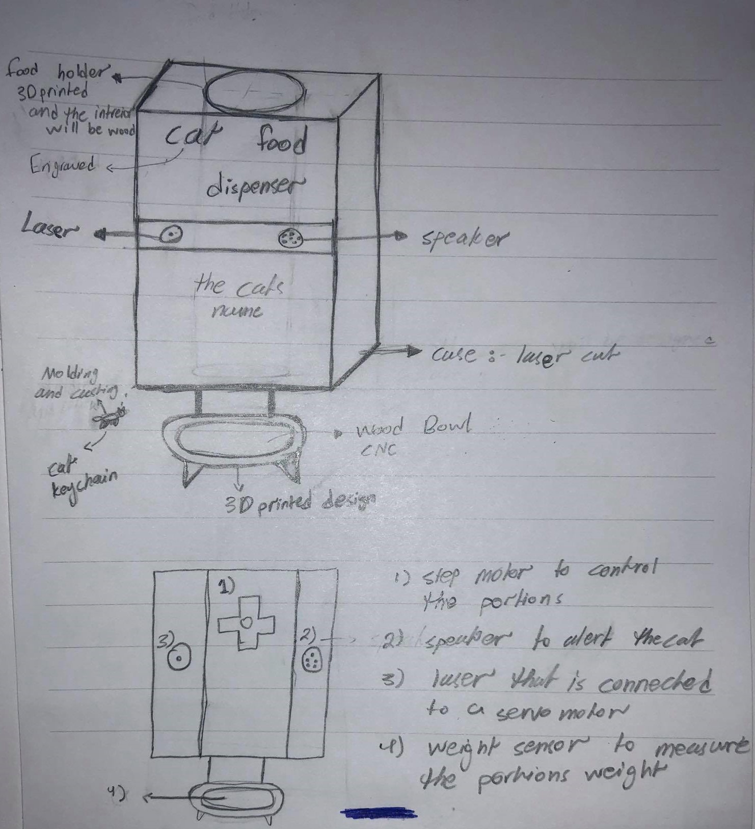
So basically ideas are like a building once you have the first floor ready you start building and building and for that i have realized that the first design was not good as a final product it was just to demonstrate the idea for my final project and i started designing new cases for the final project, finally i have ended up with this design which it took me so long to finish but if you want something to look in a good way you have to put a lot of effort on it, here is what i have come up with as a case for my final project :
-
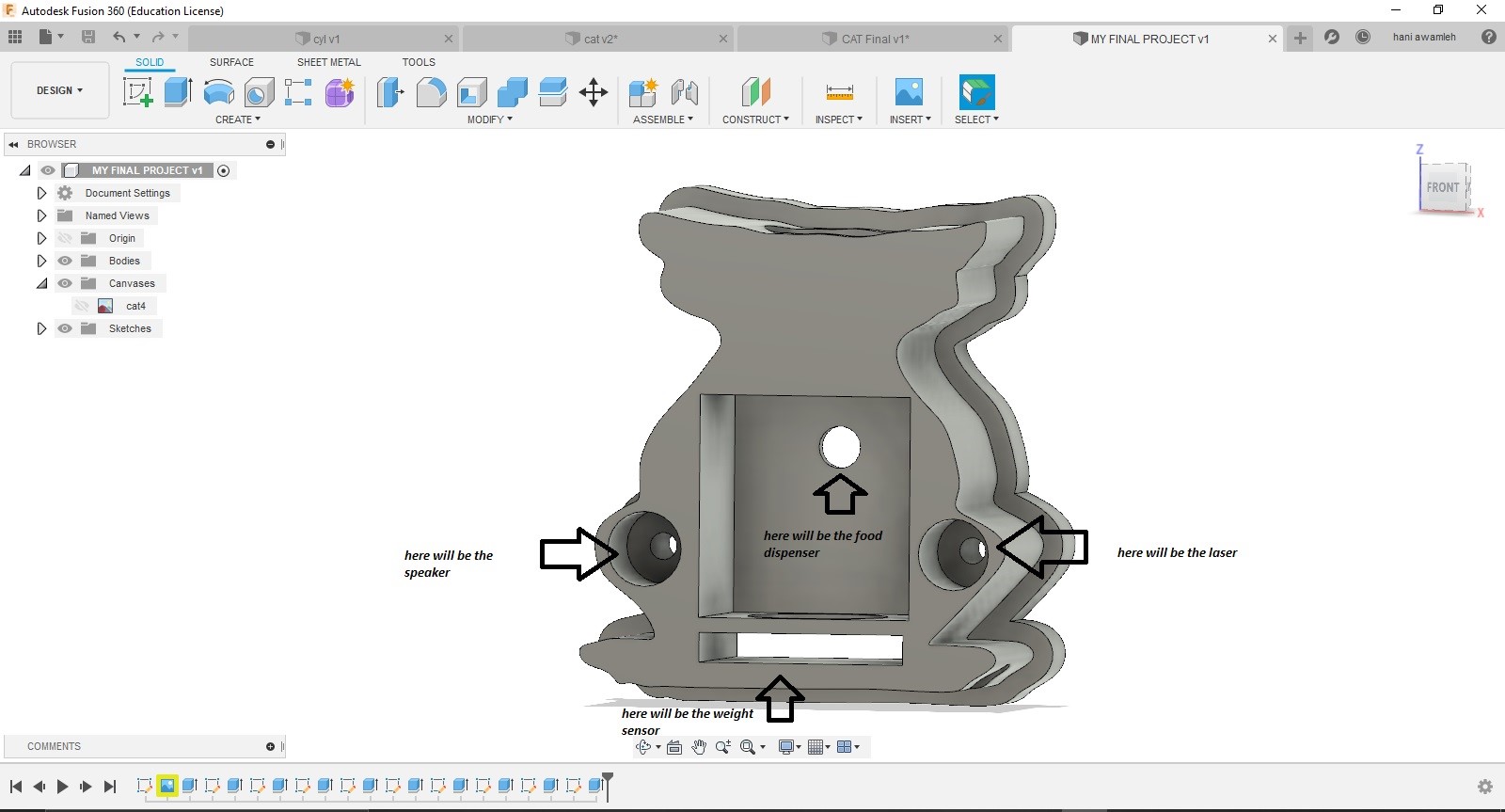
So first i designed the case using “Fusion 360” and then i saved it as a drawing in order to edit it on “Inkscape” and here is the file and a look for the design :
- Then i saved the file as DXF in order to open it on “Inkscape” and started editing and in order to come up with an accurate design and i ended up with this :
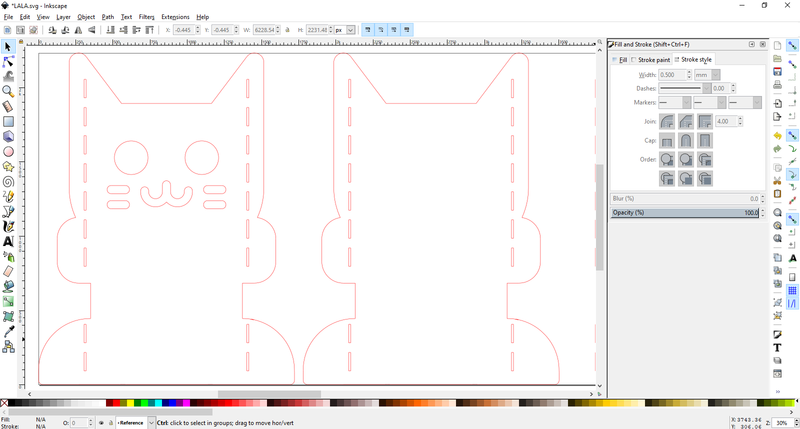
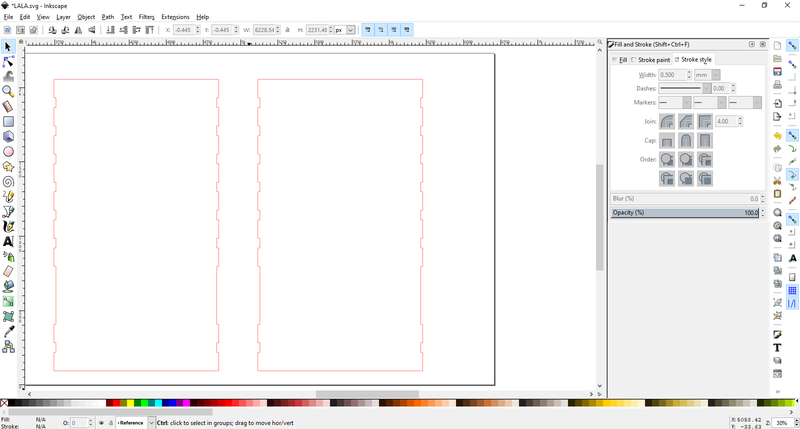
- And here is a look for the design when it is finished :
The Final project design file on Inkscape
2. Laser cutting :
-
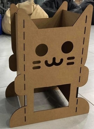
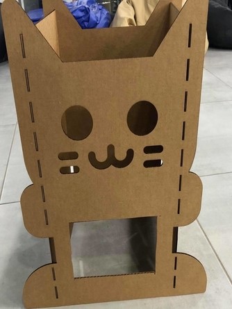
I have modified the design and tested it with mdf to see how the final look will be and here is the process :
-
First i cut the design on the laser cutter :
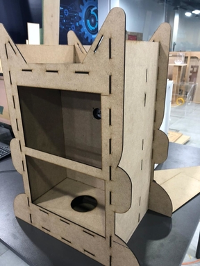
- Next i assembled the pieces in order to see if everything fits perfectly or not like this :
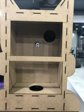
- Next i have edited the width and made it with 5mm black acrylic :
- And that will be the final look for the final design case .
Click here to see the design file
3. 3D printing :
The food portion dispenser from week 6
First i designed the dispenser using fusion 360 and onshape and here is the process :
- To design the food dispenser i have used onshape and assembled it to see if everything fits and works fine :
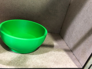
Next i designed a plate and holder for the food on fusion 360 :
- And here are the files of the 3D designs:
Click here to see the design file
Click here to see the design file
Click here to see the design file
Click here to see the design file
Click here to see the design file
Click here to see the design file
Click here to see the design file
Big thanks to Murad saadeh for the inspiration of the food portion dispenser .
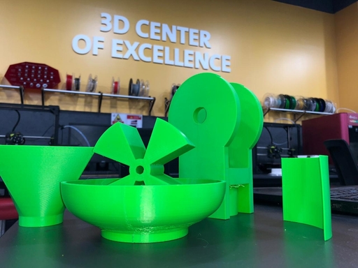
- 3D printing the designs :
- Here is the final result for the 3D printed parts .
4. Electronics design and production :
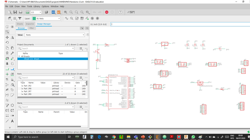
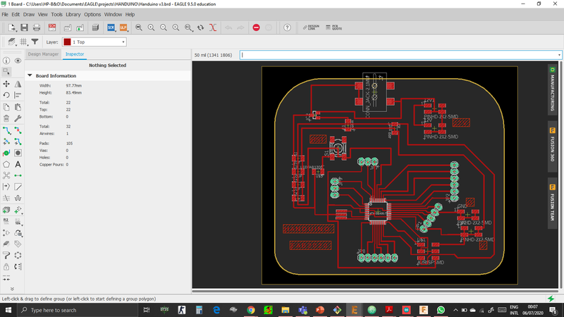
- I always wanted to make my own arduino so i have designed one and called HANDUINO and it will be the brain for my project in which the stepper motor and the weight sensor will be connected to it also the speaker.
Designing and testing HANDUINO :
- Here you can see the schematics :
- And here you can see the board design :
- Next i edited the file on gimp and here are the traces, interior and holes :
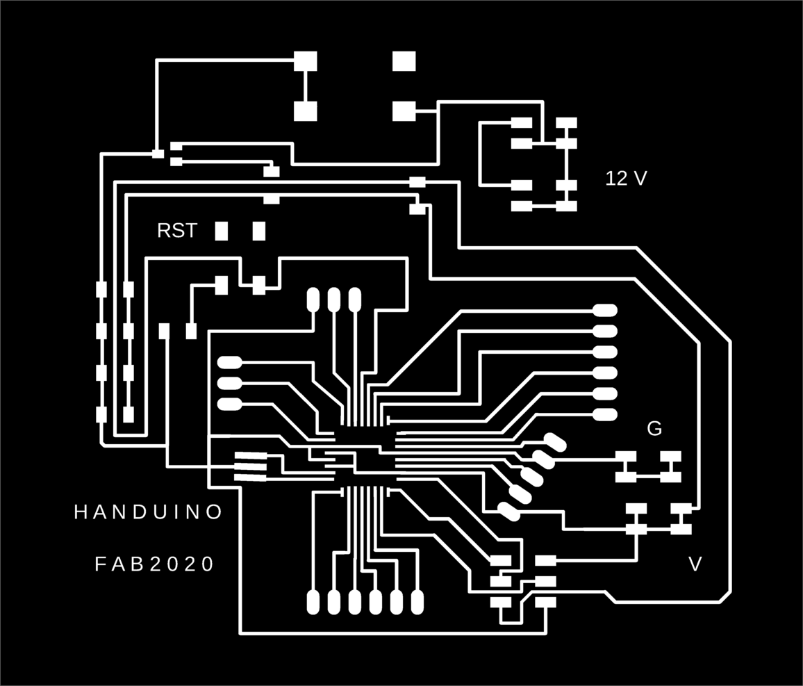


- Here are the files for Handuino :
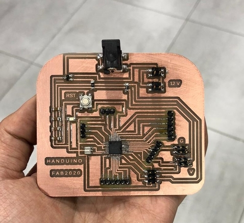
- Soldering the ATmega382p was fun :
- Now you can see the final result :
- Here i have connected my Handuino to my stepper motor board which i have made on week 12 and it worked perfectly :
Designing servo motor board :
-
i have designed a board using attiny45 and it worked perfectly with a laser on it .
-
Traces and interior :


- servo board design files :
My servo motor schematic design
- Here is the servo motor working with the laser :
Weight sensor HX711 :
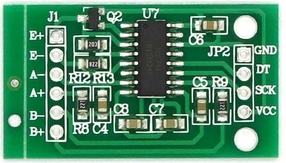
- This weight sensor is the main feature in my final project and i have been working on it for weeks but still its not working as i want so i will explain everything about it and then i will explain what is going wrong .
Explaining how the weight sensor works :
-
simply the weight sensor works by The changes in electrical resistance provided by the Load Cell need to be amplified so that they can be read by an Arduino or the ATmega382p in my case .
-
That’s exactly what the HX711 board does. It reads the information from the Load Cell, amplifies the signals and then sends it to the Arduino the ATmega382p for processing .
-
Common Load cells have four-wire to connect the HX711 to a microcontroller which are :
| red | vcc |
|---|---|
| black | gnd |
| Data | |
| clk |
- To connect the HX711 to the Arduino or the ATmega382p you only need 2 pins (Clock and Data) .
Explaining the load cell :
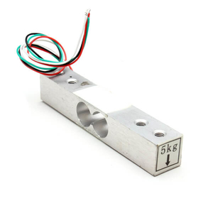
-
there are many types of Load Cell, i will be using the straight bar type 5KG .
-
When pressure or a load is applied, the electrical resistance will change in response to this applied pressure and by taking this information and after some calibration we can determine the precise weight.
-
Load cell like this one come in different weight limits, the one we will be using today is rated up to 5KG .
-
In order to connect it to the HX711 there are four wires which are :
E+ : Connected to RED of the Load Cell
E- : Connected to BLACK
A- : Connected to GREEN
A+ : Connected to WHITE
B- : no connections
B+ : no connections
calibration for the weight sensor :
-
This weight sensor needs to be calibrated before using it and that how to do it :
-
First you upload this code and put a known weight on the load cell then open the serial monitor to see if its reading the same weight you put and then start decreasing or increasing the calibrating factor until you see that the weight sensor is reading the same know weight you have put on the load cell like this :
#include <HX711_ADC.h>

#include "HX711.h"

#define DOUT  A2
#define CLK  A1

HX711 scale;

float calibration_factor = 150000;

void setup() {
  Serial.begin(9600);
  Serial.println("HX711 calibration sketch");
  Serial.println("Remove all weight from scale");
  Serial.println("After readings begin, place known weight on scale");
  Serial.println("Press + or a to increase calibration factor");
  Serial.println("Press - or z to decrease calibration factor");

  scale.begin(DOUT, CLK);
  scale.set_scale();
  scale.tare(); //Reset the scale to 0

  long zero_factor = scale.read_average(); //Get a baseline reading
  Serial.print("Zero factor: "); //This can be used to remove the need to tare the scale. Useful in permanent scale projects.
  Serial.println(zero_factor);
}

void loop() {

  scale.set_scale(calibration_factor); //Adjust to this calibration factor
  Serial.print("Reading: ");
  Serial.print(scale.get_units(), 1);
  Serial.print(" lbs"); //Change this to kg and re-adjust the calibration factor if you follow SI units
  Serial.print(" calibration_factor: ");
  Serial.print(calibration_factor);
  Serial.println();

  if(Serial.available())
  {
    char temp = Serial.read();
    if(temp == '+' || temp == 'a')
      calibration_factor += 1000;
    else if(temp == '-' || temp == 'z')
      calibration_factor -= 1000;
  }
}
- Here you can see i have started with -50 calibrating factor and then i started to increase it until i have reached the right calibration factor :
- Here you can that i have reached the right calibrating factor which is 150000 :
- The next step is seeing if this is the right calibrating factor by uploading this code and putting a known weight on the load cell :
#include "HX711.h"

#define calibration_factor 150000 //This value is obtained using the _Calibration sketch
#define DOUT  A2
#define CLK  A1

HX711 scale;

void setup() {
  Serial.begin(9600);
  Serial.println("HX711 scale demo");

  scale.begin(DOUT, CLK);
  scale.set_scale(calibration_factor); //This value is obtained by using the Calibration sketch
  scale.tare(); //Assuming there is no weight on the scale at start up, reset the scale to 0

  Serial.println("Readings:");
}

void loop() {
  Serial.print("Reading: ");
  Serial.print(scale.get_units(), 1); //scale.get_units() returns a float
  Serial.print(" lbs"); //You can change this to kg but you'll need to refactor the calibration_factor
  Serial.println();
}
- Till here everything was working fine for me and i have written this code in order to see if the weight sensor is working as i want or not, it simply says if the weight is less than my phones weight turn the LED on and if the weight is more turn the LED off and it worked perfectly :
#include <HX711_ADC.h>


#include "HX711.h"

#define DOUT A2
#define CLK  A1
#define calibration_factor 150000
// HX711 circuit wiring

float units;

HX711 scale;

void setup() {
    Serial.begin(9600);


   pinMode(2, OUTPUT);
  scale.begin(DOUT, CLK);

 scale.set_scale(calibration_factor);
   scale.tare();
}

void loop() {

  units = scale.get_units() , 1 ;
   Serial.print("Reading: ");
   Serial.print(units); //scale.get_units() returns a float
   Serial.print(" lbs");

if (units < 0.4)
{
digitalWrite(2, HIGH);

}else if(units > 0.4)
{
digitalWrite(2, LOW);


}

}
The main problem :
-
In arduino the code works fine and even with a stepper motor but when i upload this code to my ATmega382p circuit it starts to read random data as the readings starts from zero when the load cell has no weight on it and when i put a weight it starts to read that there is some weight but not the accurate one and then go back to zero like its resetting even though the weight is on the scale so the problem is im having a reading but not the right reading and its changing between zero and the wrong weight reading although all the connections are right so here is what i tried to do and did not work .
-
First i tried to connect SLK and DT pins from the module to digital pins on Handuino and it didnt work and it gave me no readings also so i connected them on analog pins A1 and A2 and i started to get readings from the FTDI .
-
Next i uploaded many libraries in order to see if its a library issue but it turned out that no its not the problem .
-
next i tried to power the module and give 5V from an out power source and still didnot work .
-
Next i thought its a baud rate problem so i have different baud rates and still didnot work .
-
Next i thought its an ADC problem but when i read about it the module is 24 BIT ADC and my ATmega382p is 10 BIT ADC so no that was not a problem it was just to give more accurate data .
-
I have talked with the gurus and they suggested to use the I2C pins on the ATmega382p which are the SCL and the SDA which are A4 and A5 on my board, but even with these connections the weight sensor didnot work .
-
The final thing to try is to change the clock form 1MHZ to 20MHZ and see if that will change the readings
-
Here i have burned the bootloader on 16 MHZ :
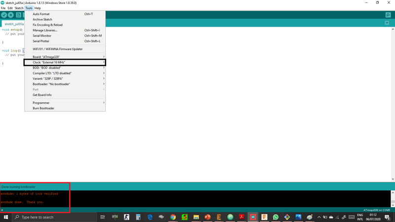
-
Finally the weight sensor did not work and i have decided to use an ultrasonic sensor.
Speaker
- This module can record a voice and play it .
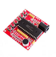
-
Im going to use a speaker in order to alert the cat and here is how i have done that .
-
I have found this tutorial very Useful so i have followed it and recorded my voice in order to call lucy my cat .
-
Here is the code for the speaker :
#define FWD 6
#define ERASE 7
#define REC 5
#define PLAY 3
#define VOL 2
#define RECLED 8 // record LED

char *label[]={" ", " ", "VOL", "PLAY", "REC", "ERASE", "FWD"};


void setup() {
  // Robojax.com OSD1700 Recorder
  pinMode(FWD, OUTPUT);// set pin as OUTPUT for FWD
  pinMode(ERASE, OUTPUT);// set pin as OUTPUT for ERASE
  pinMode(REC, OUTPUT);// set pin as OUTPUT for REC
  pinMode(PLAY, OUTPUT);// set pin as OUTPUT for PLAY
  pinMode(VOL, OUTPUT);// set pin as OUTPUT for VOL
  pinMode(RECLED, OUTPUT);// set pin as OUTPUT for RECLED (record LED)

  digitalWrite(FWD, HIGH);//turn OFF the pin: FWD
  digitalWrite(ERASE, HIGH);//turn OFF the pin: ERASE
  digitalWrite(REC, HIGH);//turn OFF the pin: REC
  digitalWrite(PLAY, HIGH);//turn OFF the pin: PLAY
  digitalWrite(VOL, HIGH); //turn OFF the pin: VOL

  Serial.begin(9600);// initialize serial monitor to display text
  Serial.println("IDS1700 Sound Recorder Player");
  record(6000);//  record sound for 6 sec
  delay(2000);// Wait for 2s
  action(PLAY);// play the last sound (the recorded sound)
}


 void action(int pin){
  digitalWrite(pin,LOW);// start the command
    Serial.print("Pin: ");
    Serial.print(pin);
    Serial.println(" Active");
  delay(400);// give it a 400ms time to execute
  digitalWrite(pin,HIGH);// stop the command
    Serial.print("Pin: ");
    Serial.print(pin);
    Serial.println(" OFF");
  delay(400);// give it a 400ms time  to stop
 } // action end


void record(int dur){
  digitalWrite(REC,LOW);// start recording
  digitalWrite(RECLED,HIGH);// set the Record LED ON
  delay(dur);// record for the dur sec
  digitalWrite(REC,HIGH);// STOP recording
  delay(300);// give stop command a 300ms to stop
  digitalWrite(RECLED,LOW);// set the Record LED OFF
}  ///record end
5.Testing the electronics :
Testing the dispenser :
- First i started with testing the main part which is the dispenser in order to see if the dispenser rotates and drops the food in the required way so i started to move the dispenser manually like this :
- Next i uploaded my code in order to see if the dispenser rotates automatically like this :
Testing the servo motor new board :
- As i mentioned earlier im going to use a laser mounted on a servo and i have a board and here you can see how it works :
- Here is the servo and laser code :
// Servo motor code

#include <SoftwareSerial.h>

// ***

// *** Define the RX and TX pins. Choose any two

// *** pins that are unused. Try to avoid D0 (pin 5)

// *** and D2 (pin 7) if you plan to use I2C.

// ***

#define RX   1    // *** D3, Pin 2

#define TX   0  // *** D4, Pin 3


// These constants won't change.  They're used to give names


// ***

// *** Define the software based serial port. Using the

// *** name Serial so that code can be used on other

// *** platforms that support hardware based serial. On

// *** chips that support the hardware serial, just

// *** comment this line.

// ***

SoftwareSerial Serial(RX, TX);


void setup() {

  // initialize serial communications at 9600 bps:


   pinMode(2, OUTPUT);

   pinMode(3, OUTPUT);
    pinMode(0, OUTPUT);
}


void loop()

{


    for (int i = 0; i < 30; ++i) {
digitalWrite(2, HIGH);
      digitalWrite(3, HIGH);
   digitalWrite(0, HIGH);
      delayMicroseconds(2000); //

      digitalWrite(3, LOW);
 digitalWrite(0, LOW);
      delayMicroseconds(18000);

    }


    delay(3000);


    for (int i = 0; i < 90; ++i) {
digitalWrite(2, HIGH);
      digitalWrite(3, HIGH);
 digitalWrite(0, HIGH);
      delayMicroseconds(1500);

      digitalWrite(3, LOW);
  digitalWrite(0, LOW);
      delayMicroseconds(18500);

    }

    delay(3000);

    for (int i = 0; i < 30; ++i) {
digitalWrite(2, HIGH);
      digitalWrite(3, HIGH);
   digitalWrite(0, HIGH);
      delayMicroseconds(2000); //
 digitalWrite(2, LOW);
      digitalWrite(3, LOW);
 digitalWrite(0, LOW);
      delayMicroseconds(18000);

    }

    delay(3000);


    for (int i = 0; i < 90; ++i) {
digitalWrite(2, HIGH);
      digitalWrite(3, HIGH);
 digitalWrite(0, HIGH);
      delayMicroseconds(1500);

      digitalWrite(3, LOW);
  digitalWrite(0, LOW);
      delayMicroseconds(18500);

    }

  delay(3000);


    for (int i = 0; i < 30; ++i) {
digitalWrite(2, HIGH);
      digitalWrite(3, HIGH);
   digitalWrite(0, HIGH);
      delayMicroseconds(2000); //
 digitalWrite(2, LOW);
      digitalWrite(3, LOW);
 digitalWrite(0, LOW);
      delayMicroseconds(18000);

    }

    delay(3000);


    for (int i = 0; i < 90; ++i) {
digitalWrite(2, HIGH);
      digitalWrite(3, HIGH);
 digitalWrite(0, HIGH);
      delayMicroseconds(1500);

      digitalWrite(3, LOW);
  digitalWrite(0, LOW);
      delayMicroseconds(18500);

    }


    delay(3000);

        for (int i = 0; i < 30; ++i) {
digitalWrite(2, HIGH);
      digitalWrite(3, HIGH);
   digitalWrite(0, HIGH);
      delayMicroseconds(2000); //

      digitalWrite(3, LOW);
 digitalWrite(0, LOW);
      delayMicroseconds(18000);

    }

    delay(3000);

        for (int i = 0; i < 90; ++i) {
digitalWrite(2, HIGH);
      digitalWrite(3, HIGH);
 digitalWrite(0, HIGH);
      delayMicroseconds(1500);
  digitalWrite(2, LOW);
      digitalWrite(3, LOW);
  digitalWrite(0, LOW);
      delayMicroseconds(18500);

    }

 delay(900000);

}
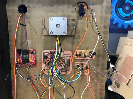
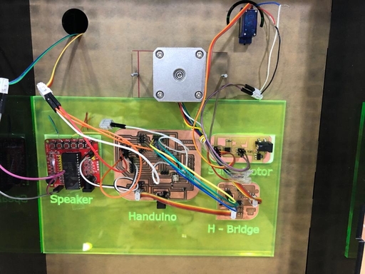
Final project electronics test :
- Here you can see all the electronics works perfectly, the ultrasonic with the stepper motor and the speaker all connected together, the laser and the servo connected together :
- Here is the code for the final project :
// This is my main code .

#include <Stepper.h>
const int trigPin = 4;
const int echoPin = 3;
#define PLAY 2
const int stepsPerRevolution = 200;

Stepper myStepper(stepsPerRevolution, 7, 8, 9, 10);
// defines variables that are used in this code !!

long duration;
int distance;

void setup() {

  pinMode(trigPin, OUTPUT); // Sets the trigPin as an OUTPUT !

  pinMode(echoPin, INPUT); // Sets the echoPin as an INPUT !

  pinMode(PLAY, OUTPUT);// set pin as OUTPUT for PLAY

  digitalWrite(PLAY, HIGH);//turn OFF the pin: PLAY

 myStepper.setSpeed(60);


}

void loop() {
//  this to clears the trigPin

digitalWrite(trigPin, LOW);
delayMicroseconds(2);

// Sets the trigPin on HIGH state for 10 micro seconds

digitalWrite(trigPin, HIGH);
delayMicroseconds(10);
digitalWrite(trigPin, LOW);

// Reads the echoPin, returns the sound wave travel time in microseconds

duration = pulseIn(echoPin, HIGH);

//  this to calculate the distance !!

distance= duration*0.034/2;

if (distance >= 23){
myStepper.step(200);
delay(5000);
 digitalWrite(PLAY,LOW);// start the command
  delay(4000);// give it a 400ms time to execute
  digitalWrite(PLAY,HIGH);// stop the command
  delay(4000);// give it a 400ms time  to stop
delay(5000);


}
 digitalWrite(PLAY, HIGH);//turn OFF the pin: PLAY


}
Final testing :
-
Here you can see the final test for electronics .
-
First i have started by testing the laser with the servo :
- Next i tested if the dispenser is working perfectly with the ultrasonic :
- Finally i have tested if the Speaker works with the dispenser and the ultrasonic :
Assembling :
- The final step is Assembling all the components so i started with packaging the electronics like this :
- Finally i assembled the case :