12. Output devices
Assignments for week 11 :
-
This week we have a group assignment and an individual assignment .
-
The group assignment for this week is to measure the power consumption of an output device .
-
The individual assignment for this week is to add an output device to a microcontroller board i’ve designed, and program it to do something .
The goal for this week is to design a board using the skills we have learned in week 7 after selecting the right output device as an output and to read the datasheet for that output device and then to cut it solder it and read it .
Files to download :
I have included all the files that you can download down below and here you can find them directly :
Group assignment :
For The group assignment this week i have to measure the power consumption of an output device and to do that we have used my colleagues board .
-
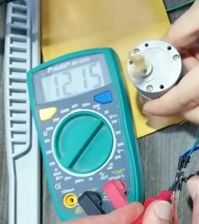
In order to complete this week group assignment we measured the power consumption of a DC motor using a DC motor output board.
-
The Power (in Watt) is calculated by P = V x I
-
V is the voltage across the load, I is the current passing through the load.
-
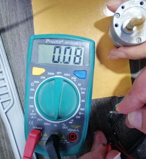
In order to measure voltage, the digital multimeter (DMM) is connected in parallel with the load, and to measure the current passing through, the DMM is connected in series with the load.
-
Remember to move DMM positive test lead to current measuring position before connecting in series with the load.
- To calculate the power consumption of the DC motor:
P = 12.15 x 0.08 P = 0.972 Watt
Individual assignment :
For the individual assignment i have to add an output device to a microcontroller board i’ve designed, and program it to do something, to start i have to decide what which ourput device i am going to use and after thinking i am going to use the speaker, stepper motor and a servo motor for this week as a step closer to my final project and to do that i am going to design each board using EAGLE, so in order to start i am going to design a board for the microphone and a board for the stepper motor also a board for the servo motor and then a FABduino to connect all the boards with my FABduino, i will start designing board by board but first i want to use My ‘Hello board’ which i have programmed in the previous week to connect it with a buzzer just to illustrate the idea of an output, Lets start !!
1. Designing my Stepper motor board :
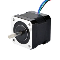
- First i started to read about the stepper motors and i have found that i can use the bipolar stepper motor and here is the Datasheet of the bipolar stepper motor i am going to use.
-
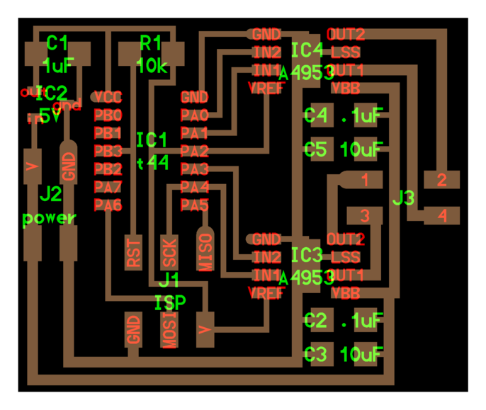
So My first step is to understand Neil’s board, The Attiny 44 is used to control the board, it can be programmed to run the stepper. There are two voltage requirements for this board. The first one is 5V to the micro controller, and the other is the 12V supply to the motor. We use an H bridge to connect the micro controller to the Stepper.
-
The H-bridge in this circuit is used as a fast acting switch. The H-bridge consist of two Mosfets one of P type and other of N type. When we give an input to one of its Input pins, It connects the High current circuit to the motor. In this way we can control a high current motor with a Micro controller.
and as i said all the boards will be designed using EAGLE so here is the process :
- Following neils board i have made my own design :
-
You can go back and check My documentation on week 7 to see every step on how to design a board using EAGLE .
-
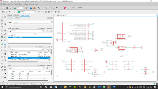
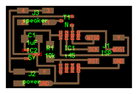
Here you can see that i have completed the schematics for my design on EAGLE and added all the parts i need :
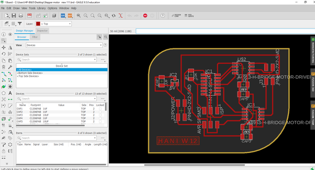
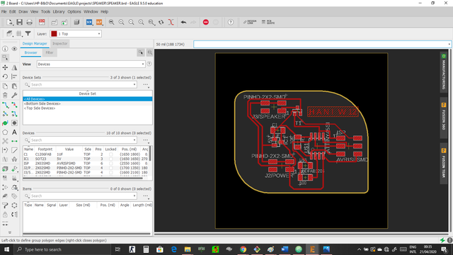
- Also here you can see the board design after i successfully routed all the connections :
- Now i exported my design and edited it using gimp in order to get the traces and the interior “outline” :
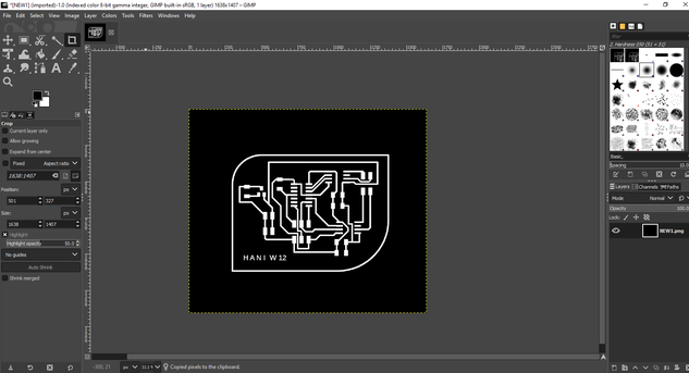
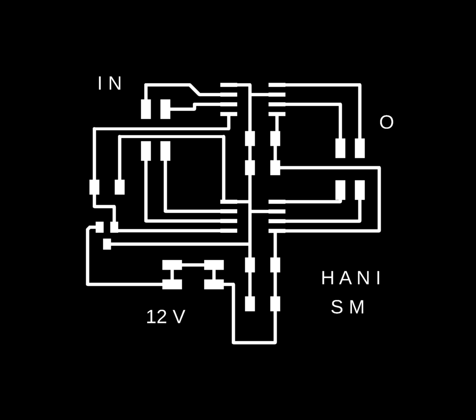
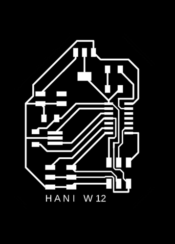
- Finally i have the design all ready so here is the traces and the interior “outline” :


- And here are the design files :
My schematic stepper motor design
Cutting the stepper board traces :
Cutting the stepper board interior :
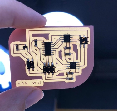
stepper motor board :
Fails :
- When i tested the stepper motor board it didnt work even though when i tested the voltage that is coming from the power source to the motor it was correct so i rechecked and i have found that the LSS pin must be connected to ground also so i have reconnected it and it worked perfectly .
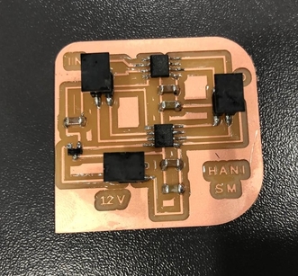
New board :
- Traces and interior :

New design files :
- here are the new design files :
My new board stepper motor design
My new schematic stepper motor design
stepper motor code :
- in order to test the stepper motor i have used Neils code
Hero shot for the stepper motor :
- Here is the board working with Handuino
2. Designing my Servo motor board :
- First i started to read about the Servo motors and here is the Datasheet of the Servo motor i am going to use, also i have added LED to my board to see if the board is working before programming the servo motor board, and as i said all the boards will be designed using EAGLE so here is the process :
- Following neils board i have made my own design, also as i said before i have added LED to check if my board is working properly :
-
You can go back and check My documentation on week 7 to see every step on how to design a board using EAGLE .
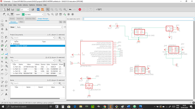
-
Here you can see that i have completed the schematics for my design on EAGLE and added all the parts i need :
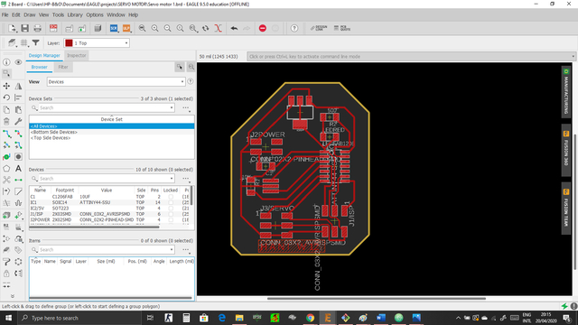
- Also here you can see the board design after i successfully routed all the connections :
- Now i exported my design and edited it using gimp in order to get the traces and the interior “outline” :
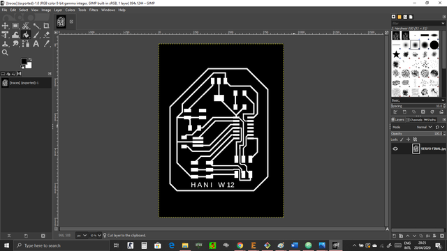
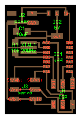
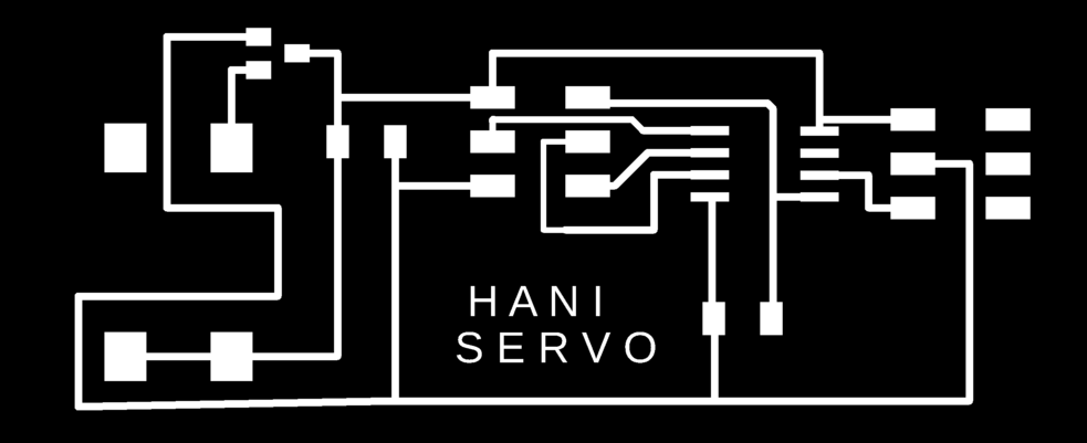
- Finally i have the design all ready so here is the traces and the interior “outline” :

- And here are the design files :
My servo motor schematic design
Fails :
- I have tested the servo motor board and it didnt work for attiny44 so i have designed a new board using attiny45 and it worked perfectly
New board :
- Traces and interior :

New servo board design files :
My new servo motor schematic design
My new servo motor board design
Hero shot for the servo motor board :
- Here is the servo motor working with the laser :
3. Designing my speaker board :
-
First i started to read about Speakers and here is the Datasheet of the speaker i am going to use, also i have added LED to my board to see if the board is working before programming the speaker board, and as i said all the boards will be designed using EAGLE so here is the process :
-
Following neils board i have made my own design, also as i said before i have added LED to check if my board is working properly :
-
You can go back and check My documentation on week 7 to see every step on how to design a board using EAGLE .
-
Here you can see that i have completed the schematics for my design on EAGLE and added all the parts i need :

- Also here you can see the board design after i successfully routed all the connections :
- Now i exported my design and edited it using gimp in order to get the traces and the interior “outline” :
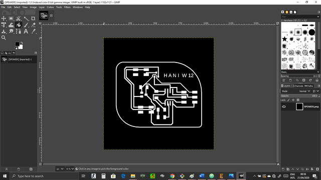
- Finally i have the design all ready so here is the traces and the interior “outline” :


- And here are the design files :
4. Servo As an output :
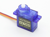
- For my final project i need two servo motors, so i started to read more and learn more on how to use the servo motor so lets start by knowing everything about a servo motor :
Wire Configuration
| Wire Number | Wire Colour | Description |
|---|---|---|
| 1 | Brown | Ground wire connected to the ground of system |
| 2 | Red | Powers the motor typically +5V is used |
| 3 | Orange | PWM signal is given in through this wire to drive the motor |
Servo motor features :
-
Operating Voltage is +5V typically
-
Torque: 2.5kg/cm
- Operating speed is 0.1s/60°
- Gear Type: Plastic
- Rotation : 0°-180°
- Weight of motor : 9gm
Keep in mind these features differs from one type to another .
Selecting your Servo Motor :
-
There are lots of servo motors available in the market and each one has its own speciality and applications. The following two paragraphs will help you identify the right type of servo motor for your project/system.
-
Most of the hobby Servo motors operates from 4.8V to 6.5V, the higher the voltage higher the torque we can achieve, but most commonly they are operated at +5V. Almost all hobby servo motors can rotate only from 0° to 180° due to their gear arrangement so make sure you project can live with the half circle if no, you can prefer for a 0° to 360° motor or modify the motor to make a full circle. The gears in the motors are easily subjected to wear and tear, so if your application requires stronger and long running motors you can go with metal gears or just stick with normal plastic gear.
-
Next comes the most important parameter, which is the torque at which the motor operates. Again there are many choices here but the commonly available one is the 2.5kg/cm torque which comes with the Towerpro SG90 Motor. This 2.5kg/cm torque means that the motor can pull a weight of 2.5kg when it is suspended at a distance of 1cm. So if you suspend the load at 0.5cm then the motor can pull a load of 5kg similarly if you suspend the load at 2cm then can pull only 1.25. Based on the load which you use in the project you can select the motor with proper torque.
How to use a Servo Motor :
-
After selecting the right Servo motor for the project, comes the question how to use it.
-
As we know there are three wires coming out of this motor. To make this motor rotate, we have to power the motor with +5V using the Red and Brown wire and send PWM signals to the Orange colour wire. Hence we need something that could generate PWM signals to make this motor work, this something could be anything like a 555 Timer or other Microcontroller platforms like Arduino, PIC, ARM or even a microprocessor like Raspberry Pie. Now, how to control the direction of the motor? To understand that let us a look at the picture :
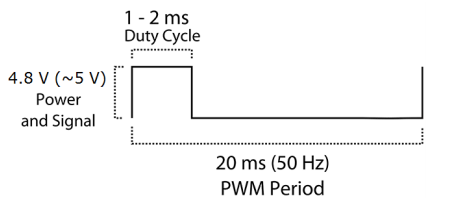
- From the picture we can understand that the PWM signal produced should have a frequency of 50Hz that is the PWM period should be 20ms. Out of which the On-Time can vary from 1ms to 2ms. So when the on-time is 1ms the motor will be in 0° and when 1.5ms the motor will be 90°, similarly when it is 2ms it will be 180°. So, by varying the on-time from 1ms to 2ms the motor can be controlled from 0° to 180°
Servo as an Output :
-
As i said, i need two servo motors for my final project and i have designed a board for that but because of the current situations i dont have access to the lab so i used Arduino to illustrate the idea of the servo motor and here is the process :
-
Programming Arduino and to do that i have written this code :
// This code to control the servo motor to rotate clock wise and counter clock wise


// This is the library needed
#include <Servo.h>

Servo name_servo;

int servo_position = 0;

void setup() {

// The pin thats the servo motor attached to :

  name_servo.attach (0);

}

void loop() {

  for (servo_position = 0; servo_position <=180; servo_position +=1){

    name_servo.write(servo_position);
    delay(10);
  }

  for (servo_position=180; servo_position >= 0; servo_position -=1){

    name_servo.write(servo_position);
    delay(10);
  }
}
The hero shoot of the individual assignment :
- And here is the servo motor actually moving :