W6"Electronics Design
This document is under Construction
- in this week "The assignments", I, WE will:
- use the test equipment in your lab to observe the operation of a microcontroller circuit board Group assignment:Group assignment
- redraw an echo hello-world board, add (at least) a button and LED (with current-limiting resistor) check the design rules, make it, and test it extra credit: simulate its operation
-Group assignment:
-Individual assignments
Hello again MR PCB, we meet again!!:
its fine, I should be used to it by now...."Than is what I thought first :("
onc again, we will use the curvy machine for making the new PCB, but now, we are also using an new program called EAGLE
ofcourse you need to sign in the program, and jsut to know, it is free... Thank you AUTIDESK!.
EAGLE can be used in this week to create the electric circuit and build the PCB, ofcourse this week, the cuircuit is provided, and we need to tweek on it
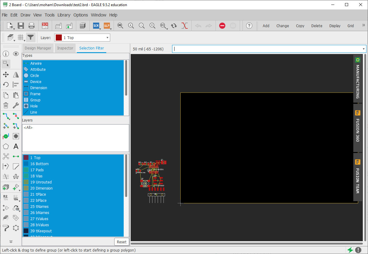
Downlaod the program, and sign in it, and lets get started:
since the main design is given by the academy, what we will do is uplad it again, but wait.. we need to redraw it :
first of all, lets add the fab academy laibrary.>> top tools bar, library and install the fab laibrary
as you can see, the laibrary is now avelable in the "ADD part" tool to the left side of the program:
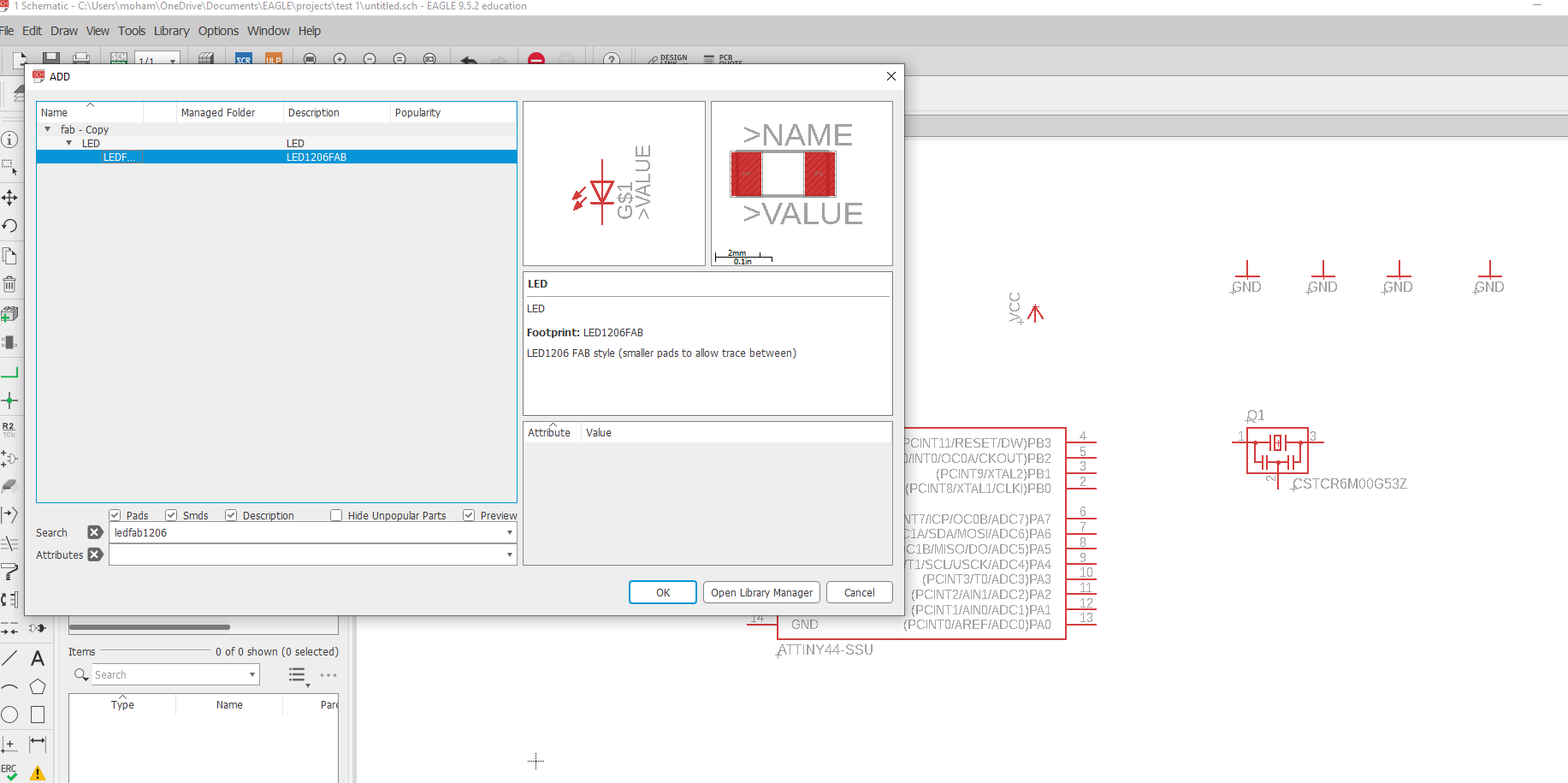
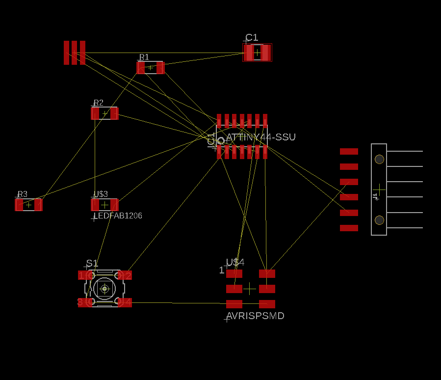
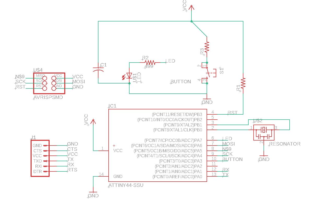
Now, lets add all the needed parts to the PCB:
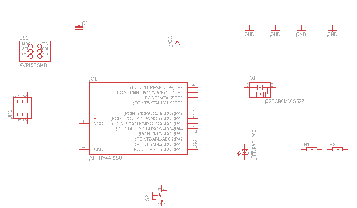
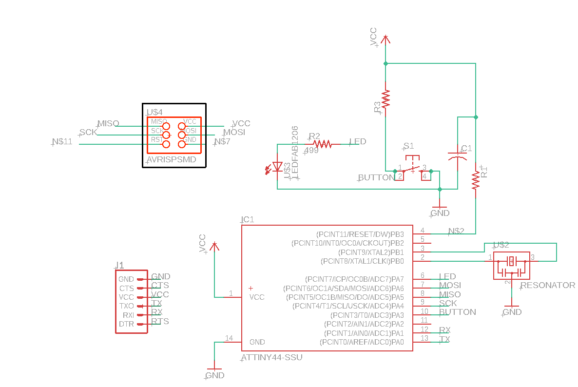
and connect them using "NET" tool to the left side of the program:
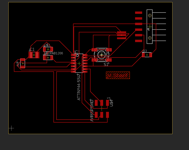
after connecting the parts, now lets go to the nest step, whitch is making the real PCB connections anddsign for the milling machine to understand:
moov all the parts inside the working area:
locate the parts in a better palce so the connection can be easeir and start connecting:
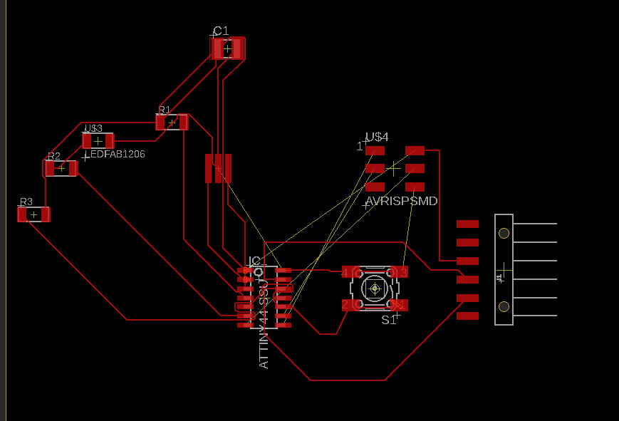
first try did not go well, try to locate the parts and do the connecting again:
ntill you come with the best and most simple one:
add your name, personalization?!?!

ready to cut, now save the design and send it to http://easel.inventables.com/, we have alleady usen it from 2 weeks befor...
lets cut some PCBz:
Wait a min, you forget to till everone how many times you cahnge the design in eagel, just show them some other desgins and the final one:
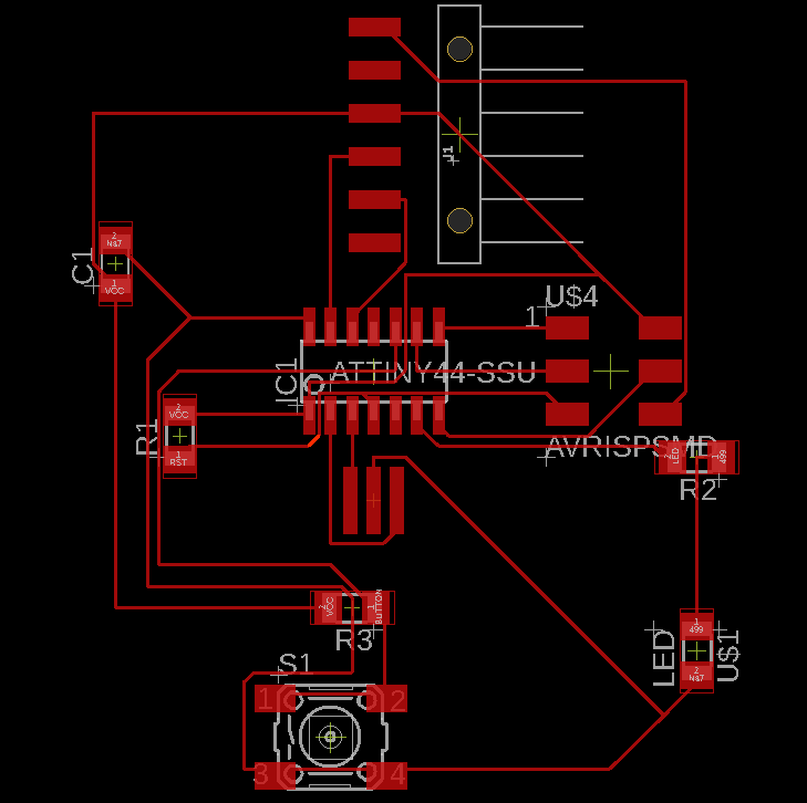
will it is true that I did that part many time, and here is one of the finest one:
and from many trys, I went with this one:
now, lets cut the PCB:
import the design to easel and change the sitting to fit for your work:
cut through the night, let the neighbors hate you some more..... >_<
morning is here, the PCB is ready:
let's do some soldering:
and the final PCB is ready:
.............................................................nope.....................................................
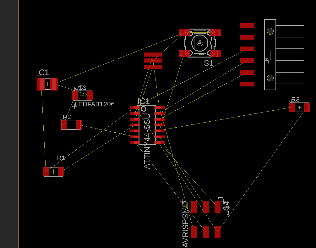
wait a min... after taking feedback from the team, and after the lockdown, I wanted do make a new V of the PCB, please check the follwing:
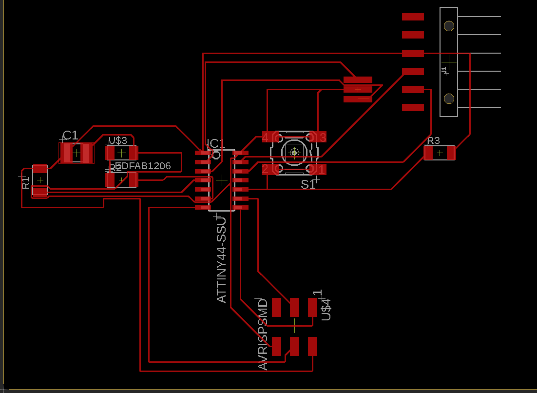
first of all, I changed the desing to have more practice on eagle software, check it here
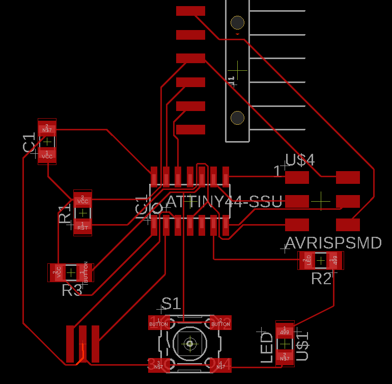
with changing the connection :
and making the connection thikness 13 in eagle (after cutting some models in our machine with 6, it did not works so will):
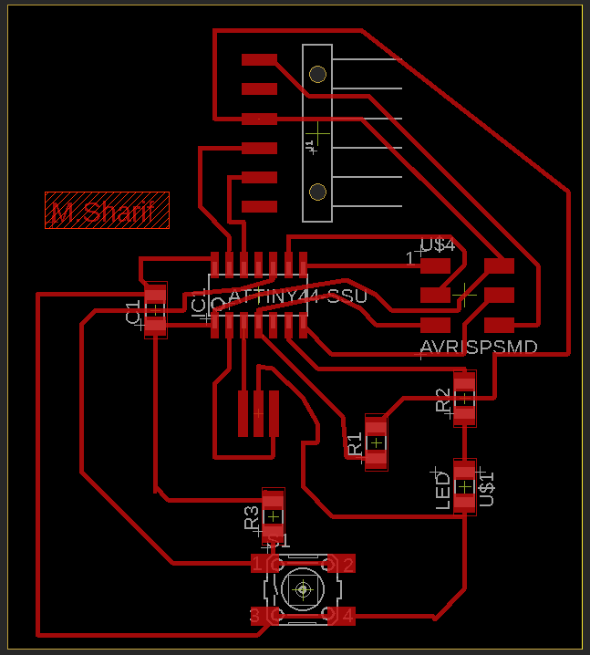
and that is the final desing form eagle...... now waiting to go back to the lab
You can find the eagle desgin in this link: Week#6+1
and here is the test of attiny44 pushbutton example:
and the code of it :
  void setup() {
    pinMode(7, OUTPUT);
      pinMode(3, INPUT);
  }

  // the loop function runs over and over again forever
  void loop() {
    int i=digitalRead(3);
    if(i==0)
    {
    digitalWrite(7, HIGH);

    digitalWrite(7, LOW);

  }
  }
Back to Group assessment, we are using the multimeter to test wour work and the conncetion, voltage of the pcb.
first of all is the conncetion, On a breadboard that is not powered, use the probes to poke at two separate ground pins. You should hear a tone indicating that they are connected. Poke the probes from the VCC pin on a microcontroller to VCC on your power supply- just as a test, I am trying to test the pins of the attiny44 to chek if it is connceted in the reigt way with the other compunents of the pcb. It should emit a tone indicating that power is free to flow from the the pin of the attiny to the connected part of it in the pcb . If it does not emit a tone, then you can begin to follow the route that copper trace takes and tell if there are breaks in the line, wire, breadboard, or PCB.
next is testing the Vcc power if it is glowing correctly in the pcb, by testing the voltage between any VCC pin and GND pin in the pcb... then testing the signal that is send fron attiny44 to the build in led in the pcb, and as you can see, when pressing the pushbutton, the led will light on and by testing the signal, you can see that the multimeter is detectin a 0.61V~ comming from the attiny to power up the led when pressing the push button: