W12"Output Devices
This document is under Construction
- low load: avg V = 4.6 and min amp = 0.08 A >>>>> so the power = 4.6 X 0.08 =0.368 W
- high load : avg V X max amp =0.3A >>>>> then power = 4.6 X 0.3 = 1.38 W
HEllo again to this humble page, this week, we will work on output devices
-Group assignment:
Group assignment:Group assignmentso after taking any reads or value from the world, and prociss it in the controller, how to do something with it ?
how to make something visibale to use, one of the ways is an real actuator.
for this week, let's use an servomotor as an actuator", you can read more about the servomotor HERE
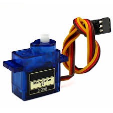
a small DC motor, potentiometer, and a control circuit. The motor is attached by gears to the control wheel. As the motor rotates, the potentiometer's resistance changes, so the control circuit can precisely regulate how much movement there is and in which direction.
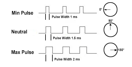
ervos are controlled by sending an electrical pulse of variable width, or pulse width modulation (PWM), through the control wire. There is a minimum pulse, a maximum pulse, and a repetition rate. A servo motor can usually only turn 90° in either direction for a total of 180° movement. The motor's neutral position is defined as the position where the servo has the same amount of potential rotation in the both the clockwise or counter-clockwise direction. The PWM sent to the motor determines position of the shaft, and based on the duration of the pulse sent via the control wire; the rotor will turn to the desired position. The servo motor expects to see a pulse every 20 milliseconds (ms) and the length of the pulse will determine how far the motor turns. For example, a 1.5ms pulse will make the motor turn to the 90° position. Shorter than 1.5ms moves it in the counter clockwise direction toward the 0° position, and any longer than 1.5ms will turn the servo in a clockwise direction toward the 180° position.
let's use my arduino(for now, nothing is available in the lockdown) to do the the controlling...
and lets use an multimeter to measure both volt and current for group work
just for your info, that power is equal to volt X current............ in aother word, if we could measure the volt and current used in the servo, then we can know the power it consumed to work.
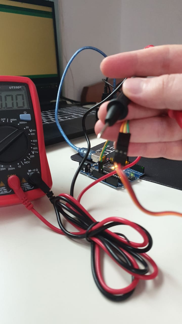
I am facing some problems with the multimeter, don't now why!!!! kind of buggy?!?
ok , then let's think in another way to measure Volt:
if you now, arduino has analog pins that can measure the value in real world , ant that value is up to 5 volt in arduino, so if you connect the 5 volt arduino pin to the analog pins and try to read the analog value, it will give you 1023... if you less volt will give you less value, in another word: each 1 volt is equal to 204.8 analog value, so we may be able you use this to measure the volt, please check the video :
when live gives you lemon...... the blue servo gears gut broken..... my luck power is over 8000.
what ever, I remembered that I have worked on another project that has servos, and its in my closed, say hi to my inmoov robotic hand:
if you don't know about inmmov, InMoov is a humanoid robot, constructed out of 3D printable plastic body components, and controlled by Arduino microcontrollers

inmoov is an open source project , check the link HERE
still facing problems with reading any value with the multimeter??! why.... keep teasting......
tooo much lag and noise in the reads:
after restarting the multimeter, and checking again, and testing more.... it just work from its own?! alot of lemon for me today? right ? life?!
now, lets test the values from operating the servo with rotating 13- degree in both direction:
reading are still funny, and noisy, lets try to lower the moving speed and the load on the servo:
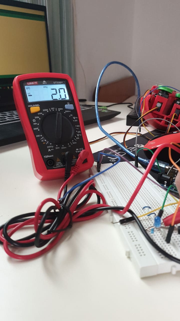
ok, more stable, so the servo is using 4.4 to 4.8 volt to rotate , lets ake an average fo 4.6 volt.
what about current, wen measuring current make sure that you are connecting the multimeter in the right way.. series
from start, with low load, the curren is 0.08 Amp and then the servo load increase, the curren reach up to 0.30 Amp.
with that, we can measure the power the servo use:
check the arduino code: The code
lets take a look at the code:
#includeServo myservo; // create servo object to control a servo // twelve servo objects can be created on most boards int pos = 0; // variable to store the servo position void setup() { myservo.attach(9); // attaches the servo on pin 9 to the servo object } void loop() { for (pos = 0; pos <= 180; pos += 1) { // goes from 0 degrees to 180 degrees // in steps of 1 degree myservo.write(pos); // tell servo to go to position in variable 'pos' delay(150); // waits 15ms for the servo to reach the position } for (pos = 180; pos >= 0; pos -= 1) { // goes from 180 degrees to 0 degrees myservo.write(pos); // tell servo to go to position in variable 'pos' delay(15); // waits 15ms for the servo to reach the position } }
just to expalne: first, we added the servo motor library "#include with that, and after naming the servo"myservo" and defined the pins which is connected to ti "pin 9 Digital PWM"
then we intered the loop that will keep working. we difined the angle that the servo can move in (0 to 180 degree) within a new value called"pos", then
that value is defined as the value of the servo. also, within 150ms time, the value of pos will incres untill it reach 180 ((pos = 0; pos <= 180; pos += 1)), once it did,
then we will go to the second loop that will reduce the dregree of the servo by one for each 15ms of time untill it reach 0 by using the code (for (pos = 180; pos >= 0; pos -= 1)) now, lets test it with attiny44, I am connecting the servomotor after downloading the code using arduino -- I am using a potintiometer to controll the movment of the output device "servomotor", cehck the pins that I am using to send the signal to and from attiny44 to the servo and the potentiometer in this picture: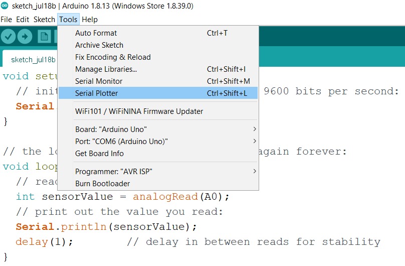
so, I am suing pin 13 from attiny44 for conrol signal from the input"potentiometer" and suing it to control the output device "servomotor" which signal pin is connected to pin 7 of attiny44
take a look at this video to se how it works:
and here is the code that I used for attiny44 to control the servo suing the potentiometer:
  void setup(){
    pinMode(0,INPUT);
    pinMode(6, OUTPUT);
  }

  void loop(){

    int x = analogRead(0);
    int y = map(x,0,1023,0,255);
    analogWrite(6,y);
  }
a very simple code to map the value of the potentiometer and send it to the the value of the servomotor
let's try one more device, A relay... What is the realy and why to use it
A relay is classified into many types, a standard and generally used relay is made up of electromagnets which in general used as a switch. Dictionary says that relay means the act of passing something from one thing to another, the same meaning can be applied to this device because the signal received from one side of the device controls the switching operation on the other side. So relay is a switch which controls (open and close) circuits electromechanically. The main operation of this device is to make or break contact with the help of a signal without any human involvement in order to switch it ON or OFF. It is mainly used to control a high powered circuit using a low power signal. Generally a DC signal is used to control circuit which is driven by high voltage
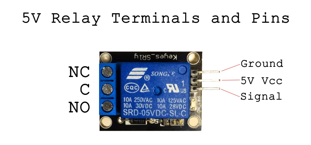
I am using a modular relay (jqc3f-05vdc-c) that has 3 inputs (vcc, gnd and control signal), the input controll signal will controll the machanical swith in the relay to connect or disconnet the circuit within the 3 outputs of (NO, NC ,C). to explain it more from the output prespictive, NO= normally closed (the circ is cormally connected), NO= normally open (the circ is cormally disconnected) and finaly C = Closed.
check the prots of the relay:
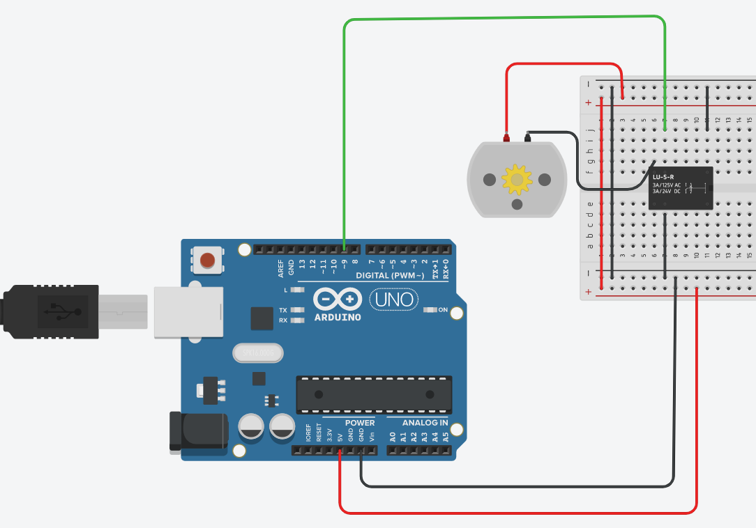
in my example, I am controlling a DC motor to turn it ON and OFF by switching the relay:
and here is the ciruit connection:
heer is the voltage used in the curcuit when the switch is ON = 0v and OFF = 5V
now, lets test the current, when theswithc is connected and the DC motor is on, current I = 0.17A at average , when the switch is off with no current passing in the circuit , I = 0A.
let's look at the code:
  int relayPin = 9;
  void setup(){
    pinMode(relayPin, OUTPUT);  //
    digitalWrite(relayPin, LOW);
  }

  void loop(){
         digitalWrite(relayPin, HIGH);  //
         delay(1500);
         digitalWrite(relayPin, LOW);
         delay(2500);
  }
this code is simple to uderstand, first we defined the pin with is giving the signal to the relay to swithc (pin9 DIGITAL) and name it relayPin and we make it an OUTPUT from "pinMode" with a value of LOW =0.
then within a loop, we will define the condition of the relay by sinding a High signal to pin9 by saving a high value to "relayPin" , and it will stay high for 1.5 S =delay(1500), then give it a low value and keep it low for 2.5S...this loop will continue ...
you can also downlaod it: The code
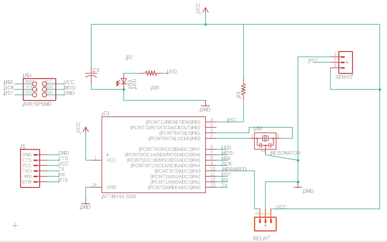
now let's take a look at the degin for the pcb circuit, I have updaterd on the design of the a previous circuit and updated it for both the the servomotr and the relay, which each one need 3 pins, 2 for VCC and GND and the their is for signal, check them below:
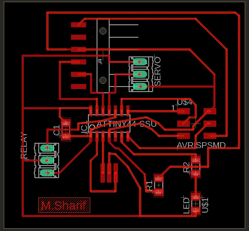
the button is connected to pin 10 in attiny44, while the relay is connected to pin 13
cehck the video to see how it works :
and here is the code for it:
  void setup() {
    pinMode(0, OUTPUT);
      pinMode(3, INPUT);
  }

  // the loop function runs over and over again forever
  void loop() {
    int i=digitalRead(3);
    if(i==0)
    {
    digitalWrite(0, HIGH);   // turn turn relay on..so DC motor will work
    delay(100);                       // wait
    digitalWrite(0, LOW);    // turn turn relay OFF..so DC motor will stop
    delay(10);                       // wait
  }
  }
from the code, if wee press the button, then the if condition is true, and the relay>motor will work....if not, then bothare OFF
check the Eagle files: eagle!
and here: eagle!