W8"Embedded Programming
This document is under Construction
- the full document is very long, my eyes........
- Pin Configurations:
- Pin Descriptions:
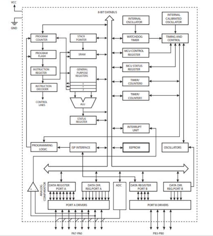
- Block Diagram:
- Arduino: Board Manager: Manage packages for boards. You can add 3rd party Arduino board by configuring Additional Board Manager URLs in the board manager.
- Arduino: Change Baud Rate: Change the baud rate of the selected serial port.
- Arduino: Change Board Type: Change board type or platform.
- Arduino: Close Serial Monitor: Stop the serial monitor and release the serial port.
- Arduino: Examples: Show list of examples.
- Arduino: Initialize: Scaffold a VS Code project with an Arduino sketch.
- Arduino: Library Manager: Explore and manage libraries.
- Arduino: Open Serial Monitor: Open the serial monitor in the integrated output window.
- Arduino: Select Serial Port: Change the current serial port.
- Arduino: Send Text to Serial Port: Send a line of text via the current serial port.
- Arduino: Upload: Build sketch and upload to Arduino board.
- Arduino: Upload Using Programmer: Upload using an external programmer.
- Arduino: Verify: Build sketch.
-Group assignment:
Group assignment:Group assignmentHEllo again to my humble page, this week, we will work on another subject;Embedded Programming
so what is Embedded Programming, and what are we going to do?
first, we will gather all the info about the chip that we are using, Attiny 44: the summary 26 page
or we you can reed the full documents for Attiny 44 the full extrem extra 238 page
and from the previous, we can understand the specs of the chip:

VCC: -supply voktage
GND: - ground
Port B (PB3:PB0): -Port B is a 4-bit bi-directional I/O port with internal pull-up resistors (selected for each bit). The Port B output buffers have symmetrical drive characteristics with both high sink and source capability except PB3 which has the RESET capability. To use pin PB3 as an I/O pin, instead of RESET pin, program (‘0’) RSTDISBL fuse. As inputs, Port B pins that are externally pulled low will source current if the pull-up resistors are activated. The Port B pins are tri-stated when a reset condition becomes active, even if the clock is not running. Port B also serves the functions of various special features of the ATtiny24/44/84
RESET: -Reset input. A low level on this pin for longer than the minimum pulse length will generate a reset, even if the clock is not running and provided the reset pin has not been disabled. The reset pin can also be used as a (weak) I/O pin.
Port A (PA7:PA0): -Port A is a 8-bit bi-directional I/O port with internal pull-up resistors (selected for each bit). The Port A output buffers have symmetrical drive characteristics with both high sink and source capability. As inputs, Port A pins that are externally pulled low will source current if the pull-up resistors are activated. The Port A pins are tri-stated when a reset condition becomes active, even if the clock is not running. Port A has alternate functions as analog inputs for the ADC, analog comparator, timer/counter, SPI and pin change interrupt
the pcb is not working, no fablab open in KSA, what to do,>>>>>>>>>>>>>>> Thank you arduino :
to make things simple, we don't have access to any fablab or any machines in the lab, so I will use arduino:
lets use what we have in our hands.....best of luck for all fablabers, stay home ....
start with connecting arduino adn the led, pushbotton , breadbaord and connctors to the pc :
and that's how it will work :
here is the blocks coding :
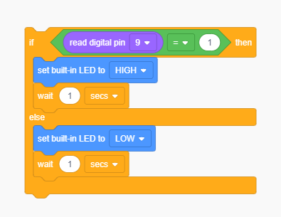
you can see the work in tinkercad platform by seraching on the link HERH
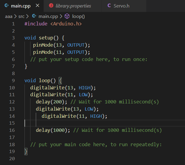
or you can find the arduino IDE code : The code (LED_BLINK_W8)
I am using arduin, with c++ programing langudge , for extra..I am also using blocks programing from tinkercad, it works like simmulation and coding with both c++ and blocks, you can select directrrly the outcomes form you connections and coding using the simmulations provided in the website, check the website HERH
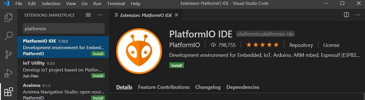
how about more platforms, lets try visual studio code with anduino extntion:
for arduino comment on visual studio , look for the following:

see the extintion HERE
or use platformIO on VScode, but first, downlaod VScode from HERE
after wonlaoding the extension, we can start coding using it:
check HERE to learn more details about dealing with arduino within VScode
after searching the web, I found that platformIO is simple to use in VScode, you can downlaodint from "extentions" within VScode:
now, open new prpject:
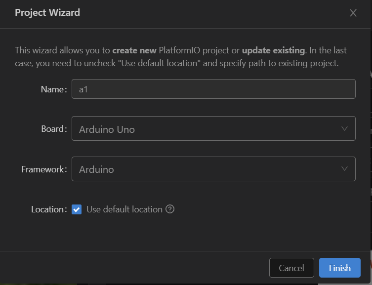
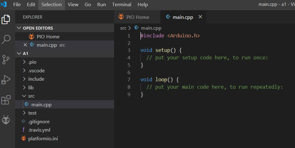
you will find the working file here:
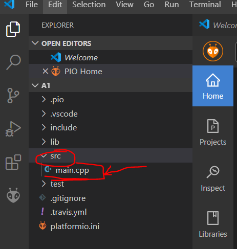
you can see the usual code....
lets add owr code:
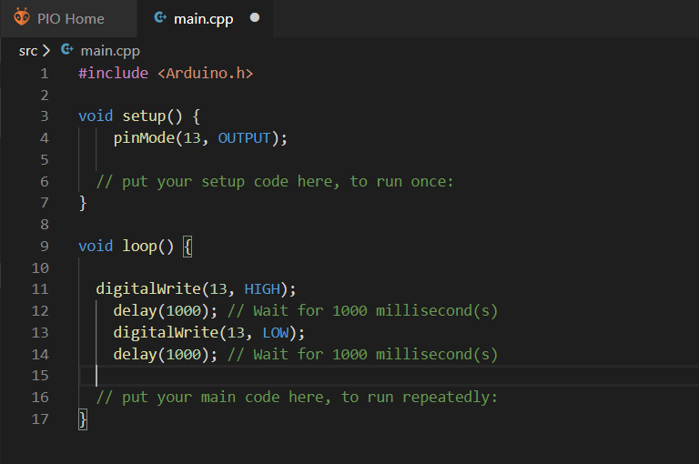
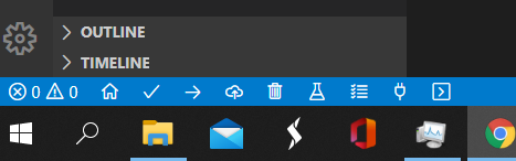
and like many softwares, you can check your code,then send it to the micro controller:
lets controll more elements anc tweek the code a little "the lockdown make working in the fablab imposible... so I am using what I have of electonics to build this"
check the arduino IDE code: The code
Now, lets try to write the code in C langudge.... The first thing you need to know about programming in C for Arduino is to know how to compile and upload the binary code onto Arduino board
with new arduino IDE, you can uplaod C langudge to the board, and it will run after processing to arduino normally as if you were working with C++... note that you may face some problems if you are using old arduino IDE software, 16.2V adn higher is ,ore stable for this task...
first is the code:
#include#include #define BLINK_DELAY_MS 1000 int main (void) { DDRB |= (0x20); DDRD |= (0x08); while(1) { PORTB |= (0x20); _delay_ms(BLINK_DELAY_MS); PORTB &= 0xDF; // you can do PORTB &= ~(0x20) _delay_ms(BLINK_DELAY_MS); PORTD = PORTD | 0x08; _delay_ms(BLINK_DELAY_MS); PORTD = PORTD & 0xF7; _delay_ms(BLINK_DELAY_MS); } }
so within this C code, I am defining the ports that are outputs form the blinking, with 2 LEDs, one is connected to pin 13 (built-in LED) and the the other LED is connected to pin 3 || DDRB |= (0x20); for pin 13___ and DDRD |= (0x08); for pin 3 in the digital pins
then within the while(1) condition, which means TRUE (or the condition is true and it will give high signal), then the pin 13 is defined to high in the code ( PORTB |= (0x20);) and after a delay using ( _delay_ms(BLINK_DELAY_MS); ) which is defined in the start of the code as 1000ms in (#include <.util/delay.h> and in #define BLINK_DELAY_MS 1000) after the delay, pin 13 will trun off using PORTB &= 0xDF;or you can use PORTB &= ~(0x20)
the same is happining to pin 3 which is defined in C languge as (DDRD |= (0x08)) and ti run on with the code (PORTD = PORTD | 0x08;) and off with the code (PORTD = PORTD & 0xF7;)
check the C code: The code
and you can see the resoults here:
and here:
circuit for the test :
