W9"Input Devices
This document is under Construction
- you for me, I am using tinkercad circuits for the simulation and connections. and for coding, I am using Arduino IDE
HEllo again to this humble page, this week, we will work on input devices
to make it simple, how to let your computer sence anthting from the outside ? sensors, input.... correct
we need to send the changes to the computer or microcontroller, by using a sencer or an input device
-Group assignment:
Group assignment:Group assignmentnow, let's use a simple input, an analog input "potentiometer" which is a varuable resistor that can change value depends on the rotasion of its shaft__ and we will measure the value "resistance, and the rotation angle", you can reed more about it HERE
let's use my arduino(for now, nothing is avelabe in the lockdown) to do the measureing... +did you check aruino new tools in thier website, looks cool: HERE
lets start with the coding, let's write a simple code to read the analog signal form the potentiometer:
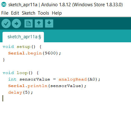
check the arduino code: sketch_apr11a
just a remainder to set everything correctly:

in this code, we used "Serail.print" with the wanted pins that is connected to the sensor to show the reads of it:
so the reads of the potentiometer is an analog that its varuable is mapped from 0 to 1023 from , and that reads is shown with the serial monitor tool in arduino IDE
also from future work, you can seen the reding more clear with the interfacethat I made from interface week:
now lets make the measurments for the sensor more visable by showing it in an led
first, lets map sit the reads of the potentiometer to a new value that is connected to a LED, check the code:
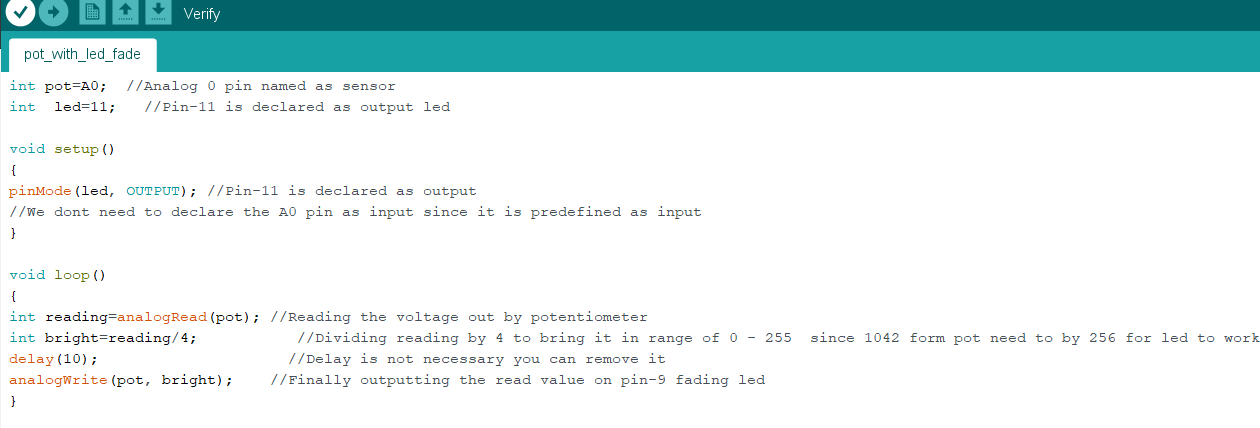
check the arduino code: pot_with_led_fade
and connect the circutie with arduino.... here is the connection:
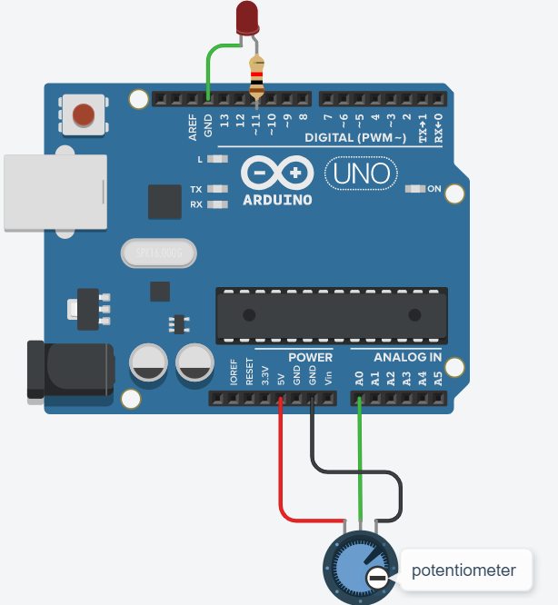
and here is the test in real live, that show the signal of the potentiometer with a LED
just to know that the value of potentiometer is 0 to 1023 , and the value for the led is 0 to 255. so we need to map it by divicing the potentiometer value by 4, check it with the prevoius code above.
the potentiometer has a value of 1M ohm, and it can rotate 300 degree, for that, if I rotate it for 150 degree, then Ithe arduino is measureing a value close to 500 in the serial monitor, in another word : (1000000 ohm devided to 300 dgree = 3333 ohm for each degree of rotation of the shaft)>>> and the same can be sade to the readings and the led fading : (1000000 diveded to reads of analog pin 1023 = 977.51 for each 1 of the analog reads)......in the end we can say that each 4 change in + or - from the analog read will increase or readuce the led light by 1 value>>>>>>that means for (977.51 ohm X 4 analog value reads) is equal to a 1 increas or decreas of the signat that is sent to the led to fade or be brighter.

for the group assessment, lets take "probe an input device's analog levels and digital signals" for that I will use the serial plotter tool:
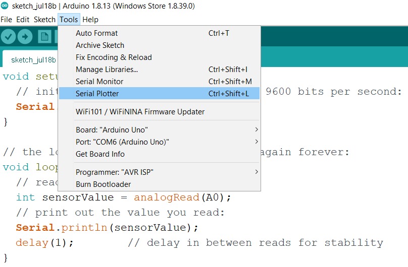
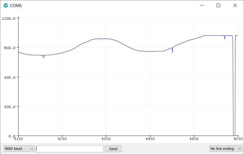
let's use an analog serial monetaring code , that will read the analog signal form a potentiometer connceted to A0, and plot it using the IDE arduino, check the code:
    void setup() {
  Serial.begin(9600);
}

// the loop routine runs over and over again forever:
void loop() {
  int sensorValue = analogRead(A0);
  Serial.println(sensorValue);
  delay(1);
}
if we wnat to take the voltage out of the analog pin, then we only need to device the value that comes from it to 204.6 ---->so the you need to change the code to "Serial.println(sensorValue/204.6)" , with that, the plotter will show the volage of A0 pin:
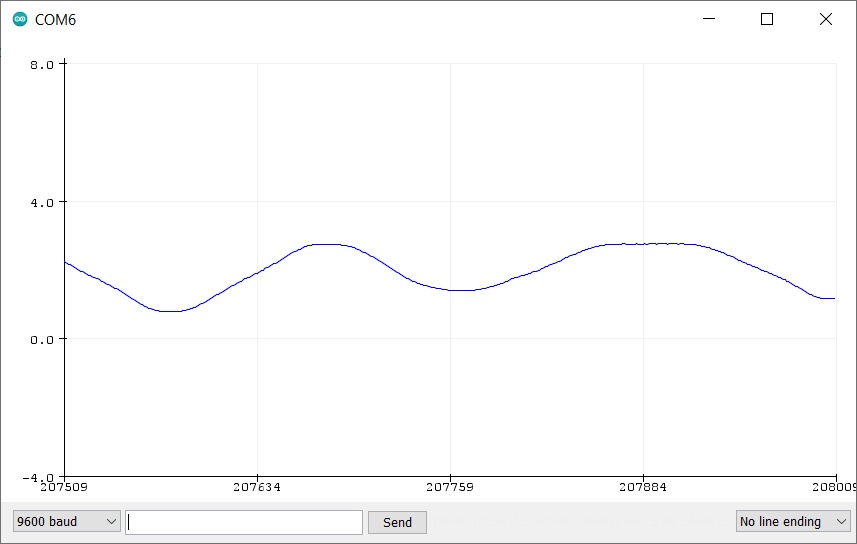
agind this time but with digital signal from the proximity ir sensor , you can find more detials about it bleow in this page... anyway for the graou assessment, let's plat some digital signal as will.
as you know, digital is 0,1 only, so if the proximity sensor is senesing something neerby, then it will give 1, if not, then the signal will be 0, and that is what I got in the plotter:
and the code is very similar to the last one, but this time ,we are reading a digital signal:
  void setup() {
  Serial.begin(9600);
}

// the loop routine runs over and over again forever:
void loop() {
  int sensorValue = digitalRead(5);
  Serial.println(sensorValue);
  delay(1);
}
now, let's connect it to attiny44 , check the picture :
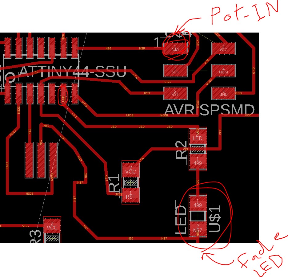
so we are connecting the potentiometer in pin 13 in attiny, adn we are suing the build in led within the same pcb that I have designed, which is conencted to pin 6 in attiny44
take a look at the video to see how it works:
and for the code, check the following:
  void setup(){
    pinMode(5,INPUT);
    pinMode(7, OUTPUT);
  }

  void loop(){

    int x = analogRead(5);
    int y = map(x,0,1023,0,255);
    analogWrite(7,y);
  }
more input sensor, lets talk now about FC 51 InfraRed proximity , which is I will use it to meauser and detecte the distance:
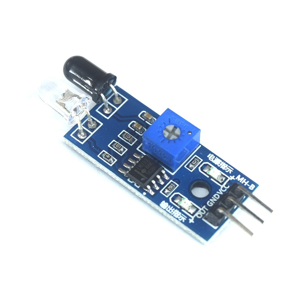
this sensor uses infrared light and send it from one side , then the infrared light reflicted on the object or obstical and go back to the receiver
lets take a look at the circuit and the connections:
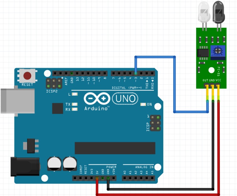
the sensor has 3 pins: VCC for 5V, GND and finaly a the signal which called OUT
just to know, the sinsor is giving an digital 0 or 1 reads to the arduino, and to change the sensetivity of the sensor, you need to change the value (rotate) the potentiometer on the sesnor baord to cahnge it sensetivity
and as you can seen in the following, if my finger is in the rage of the sensor , the led inside both the sensor board and the light built in the arduino will light on:
a fast look to the code:
  const int ProxSensor=3;

  void setup() {
    pinMode(13, OUTPUT);
    pinMode(ProxSensor,INPUT);
  }

  void loop() {

    if(digitalRead(ProxSensor)==HIGH)
               {
                 digitalWrite(13, LOW);
               }
    else
              {
                digitalWrite(13, HIGH);
               }
    delay(100);

  }
in the code, we are Definding the sensor as "ProxSensor" and it is connected to pin 3 digital input, also, we diginded the LED output in pin 13
then within a loop we added a condition thet if the reads from the sensor is high (when my finger is neer the sensor) then the condition is correct and the LED in pin13 will turn option
if the condition is not correct(my finger is far from the sensor and it can NOT detecte it) then the "else" condition will happen = LED in pin 13 will NOT work
this loop of conditons will happen in each 0.1 sec, becouse we added a delay(100)
check the arduino code: InfraRed_proximity
now let's take a look at the degin for the pcb circuit, I have updaterd on the design of the first circuit and added the connection for both the potentiometer and the InfraRed proximity sensor, which each one need 3 pins, 2 for VCC and GNG and the their si for signal
check them below:
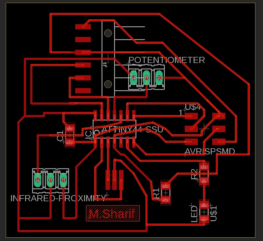
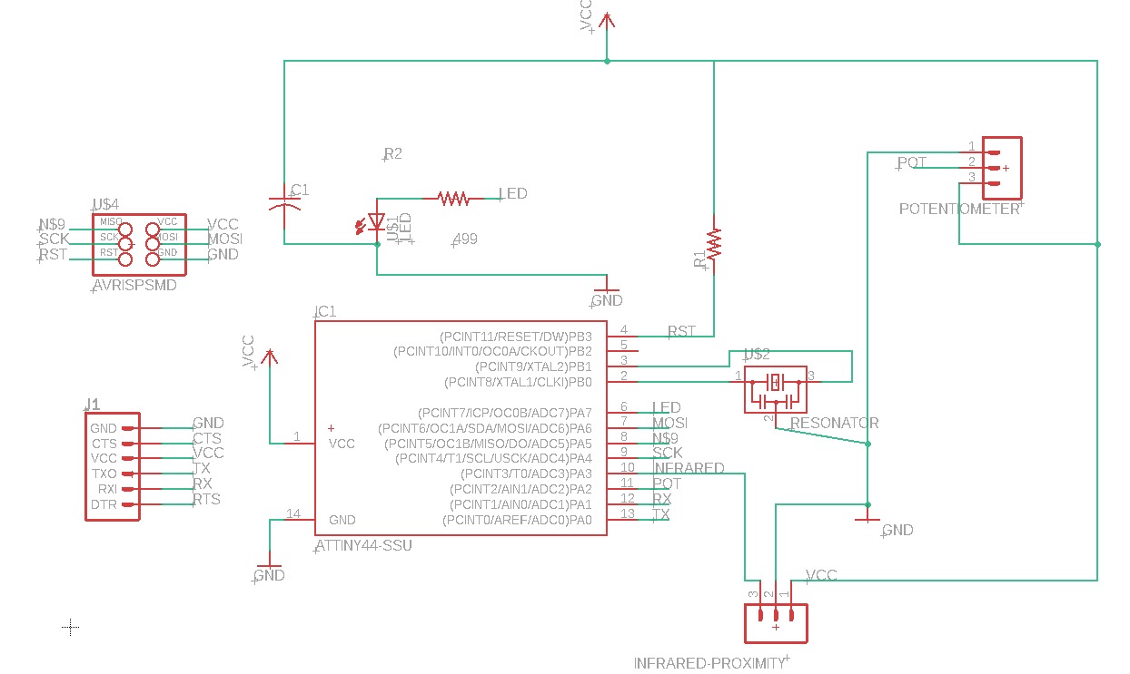
I am connecting the sensor to attiny44 using its pin 12,, and I am using the pcb built in led ,which is connected to pin 6 in attiny44
check the code here :
  void setup() {
    pinMode(7, OUTPUT);
      pinMode(1, INPUT);
  }

  // the loop function runs over and over again forever
  void loop() {
    int i=digitalRead(1);
    if(i==0)
    {
    digitalWrite(7, HIGH);

    digitalWrite(7, LOW);

  }
  }
in this simple code, if the condition in if statment is true"something is neer the sensor", then the led will ligh on
also see this vdeo to understand how it works:
check the Eagle files: eagle!
and here: eagle!