W13"Interface and Application Programming
This document is under Construction
IN this week, let's write an application that interfaces a user with an input
-Group assignment:
Group assignment:Group assignmentto make it simple, how to show your controller reading in a fancy way? in your own design and graphics, other that that provided by arduino as an example...
for that, I will use "processing" program, what is processing you ask?
Processing is a flexible software sketchbook and a language for learning how to code within the context of the visual arts, the link for it is HERE
first, downlaod processing then open it, it looks like arduino ide software...
what we will excatly do, we will make some examples to show the readings from the sensor (potentiometer) in numbers one time and in changing the color in a nother
first, let's start with potentiometer and numbers:
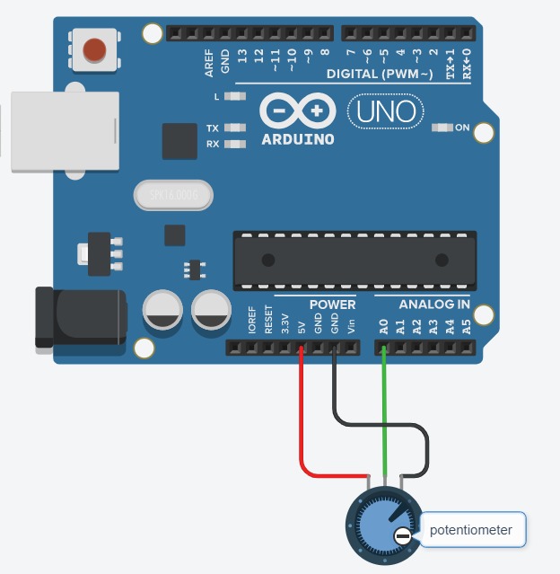
it is connected to arduino with 3 pins, on the left side pin of the potentiometer is a 5V pin to the arduino, the pin to the right is for ground GND and finaly the pin in the center is for signal, and it is connected to A0 (analog 0 pin) in the arduino
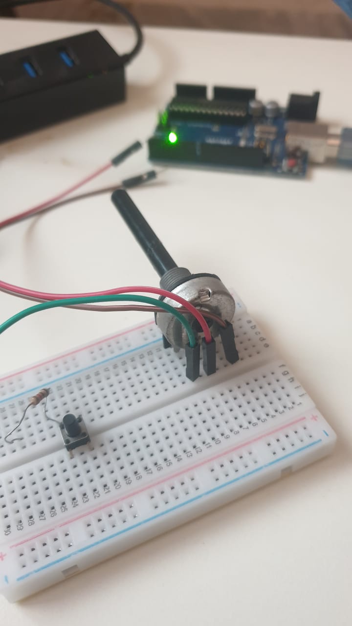
the potentiometer I am using is 1M ohm, now connect it to the arduino:
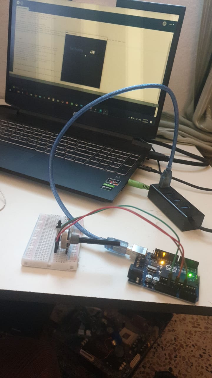
OK, now code testing, lets print the value of the potentiometer reads :
as you can see, when rotating the potentiometer the value is changing within the interface of processing
what about the code?
for arduino code, lets see it here:
    int sensorValue0;

    void setup() {
      Serial.begin(9600);
    }

    void loop() {
      sensorValue0 = analogRead(A0);
      Serial.print(sensorValue0);


      delay(50);
    }
lets explain the arduino code: but first , you need to know that I am conniction the arduino to port COM9 to my PC, you need to define that port in the next Processing code to connect the arduino readings to the interface designed by Processing.
so we are defining a reading from the esnsor which we named "sensorValue0" and within the code, we are printing a message using Serial.begin(9600) in the void setup and Serial.print(sensorValue0) and the message will be shown in each 50 ms
for Processing code, lets see it here:
    import processing.serial.*;
    Serial myPort;
    String data="" ;
    PFont  myFont;
    void setup()
    {
    size(500,200);
    background(0);
    myPort = new Serial(this, "COM9", 9600);
    myPort.bufferUntil('\n');
    myFont=loadFont("AgencyFB-Bold-48.vlw");
    textFont(myFont,70);


    }
    void draw()
    {
      background(255);
      textAlign(CENTER);
      fill(0);
      text(data,350,155);
      textSize(60);
      fill(#4B5DCE);
      text("Pot. Reading",155,150);
       noFill();
       stroke(#4B5DCE);
       rect(10,80,400,80);

    }
    void serialEvent(Serial myPort)
    {

      data=myPort.readStringUntil('\n');
    }
let's now explain Processing code, previously we used COM9 to connect arduino to PC, and here we are defining the same port in processing, so the reads from the arduino is sent to processing (myPort = new Serial(this, "COM9", 9600)), as you can see, we are using the same timing "9600".
as you can see in the next part , we are difining the font that is used in the interface"AgencyFB-Bold-48.vlw", then the size of it :
  myFont=loadFont("AgencyFB-Bold-48.vlw");
  textFont(myFont,70);
last part is the main design for the interface called "void draw" from font, color, back ground color and shape with adding some shapes to put the reading inshde:
  void draw()
  {
    background(255);
    textAlign(CENTER);
    fill(0);
    text(data,350,155);
    textSize(60);
    fill(#4B5DCE);
    text("Pot. Reading",155,150);
     noFill();
     stroke(#4B5DCE);
     rect(10,80,400,80);

  }
we can defin the color, size and location as you can see in (background(255)) for color , (textAlign(CENTER)) for location and for one more example there is the size for the rectangular in (rect(10,80,400,80)). The smae can be seen in the next example in this week with using the cange of colors do present the changes in potentiometer readings.
check the arduino code: Arduino code
check the processing code: Processing code
now, let's check another way to show the readins of the sensor, in color this time
... so if the value is 0 then the color will be white, and if readings are 1023 from the analog pin, then the color will be darker:
for arduino code, lets see it here:
  const int darkPin = A0;      // sensor to control dark color

  void setup() {
    Serial.begin(9600);
  }

  void loop() {
    Serial.print(analogRead(darkPin));

  }
for this arduino code, we are defining a constant named "darkPin" and it is connected to A0;analog 0 pin in arduino.
then we are presenting that value... this value will be used in the net processing code :
for Processig code, lets see it here:
  import processing.serial.*;

   float darkValue = 0;        // dark value

   Serial myPort;

   void setup() {
     size(200, 200);


     println(Serial.list());

     myPort = new Serial(this, "COM9", 9600);
     myPort.bufferUntil('\n');
   }

   void draw() {
     backgrounddarkValue;
   }

   void serialEvent(Serial myPort) {
     String inString = myPort.readStringUntil('\n');

     if (inString != null) {
       inString = trim(inString);
       float[] colors = float(split(inString, ","));
       if (colors.length >= 1) {
         darkValue = map(colors[0], 0, 1023, 0, 255);

     }
   }
   }
so the reads from the arduino is sent to processing (myPort = new Serial(this, "COM9", 9600)), as you can see, we are using the same timing "9600"
we are also defining the size of the interface window by 200 for x and 200 for y using the code within thevoid setup() (size(200, 200);)
then within void draw(), we are difining that the color "value" of the background of our interface will be definded by "darkValue" wich is the same reads that we are taking from the arduino...
if there is no reads, then the value will still the same, but if we are picking any change in reads from arduino, then we will go with the condition:
      if (colors.length >= 1) {
        darkValue = map(colors[0], 0, 1023, 0, 255);
darkValue = map(colors[0], 0, 1023, 0, 255);the cahnges in reads from arduino to the cange of colors from black to white; if the readis from the analog pin from arduino is 0 then the color will be white in processing, if the reading changed neer to 512, then the color in processing will be gray,,,and so on untill it reach 1023 , then the color will be black
check the arduino code: Arduino code
check the processing code: Processing code
if you want to know more about processing coding, you can cheack the following links: