W15"NETWORK AND Communications
What to do?
- I2C is more flexible and Less complexity and the design is elementary.
- You can use chip addressing, this will help us to add components to the bus.
- error can be deticter easeir in I2C.
- I2C is used in many machine.
- Far easier to use than other protocols like SPI.
- Uses fewer connections than SPI.
- Supports a multi-master system, rather than SPI’s one master, infinite-slaves system.
- 100% compatible with our Arduino Uno.
HEllo again, in this week, we will owrk on connecting 2 micro controllers together using a signal sequences know as communication protocols.
in another world, we will build a system that send signal (order) from a master controller TO another arduino (Slave) to do the work
there is many way to communate between 2 contorlles, and the one that we will use in this week is I2C protocol
+ jsut to know that we will use a wire coomunication , so I2C for this week
Benefits of I2C:
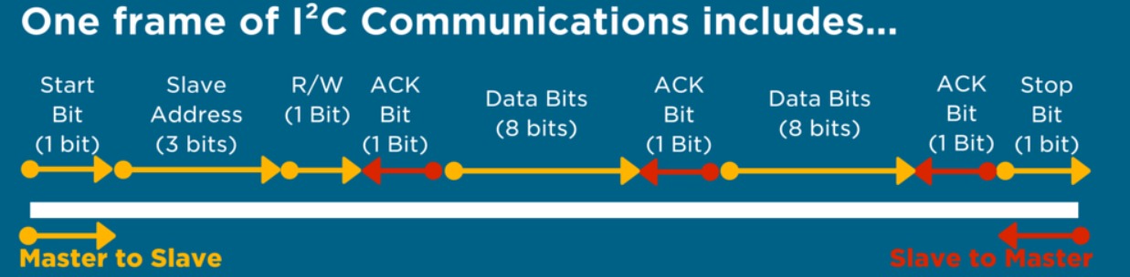
what is the shape of the signal that is sent by I2C, it is a serice "1" one bit at a time through a each communication channel:
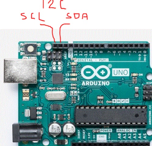
now, let's go and check the pins that we use for I2C connections, from the digital side pins n the raduino uno as example, after pin 13 and GND, you will find 2 more pins, there are for connicting I2C and colled SCL and SDA:
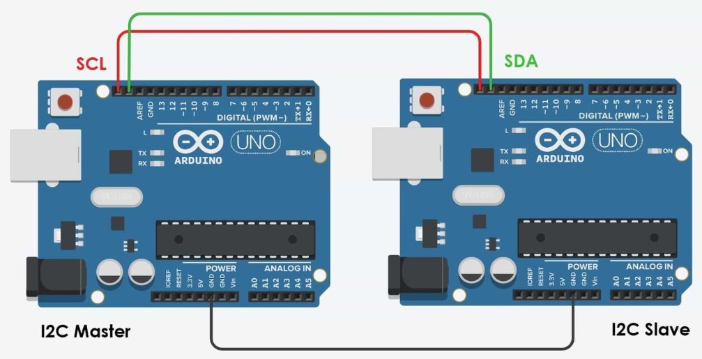
you also need to now that for making any communication work for the controller, arduino as exmaple, you need to make the GND commit between the master and the slave
how to start understanding new tech, simply, read and watch.... for example use this you tube video or this link from arduino to undestande the main idea of communication "know that they may use different connection, but this will help U understand more the main idea":
Arduino here
anyway, let's try suing the write this code in Master arduino
, using Wire library to udentify that we are using master and slave, and beginning the code with "Wire.begin()" without value for master as a test and serial monitor moniter :after wirting the codes for both master and slave, Connect the USB the arduinos to the pc and uplaod the code........"note that you need to remember wich one is slave or master , you can do that by looking at the port name , COM3,4 and so on"__ for my case it is COM 6 for master, and COM 9 for slave
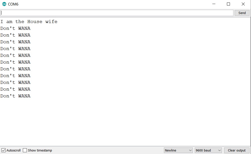
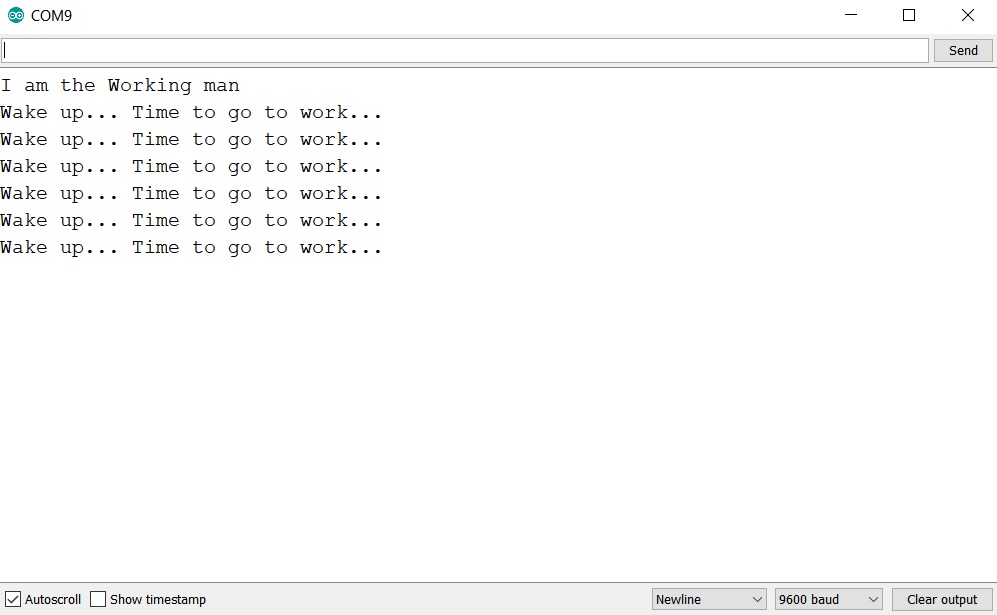
after uplading the codes, open the serial monitor to start the communication and see the mesegaes between the working man and the house wife:
serial monitor from the Master :
serial monitor from the slave :
    //Master arduino//
    #include

    void setup() {
      Wire.begin();
      Serial.begin(9600);
     Wire.begin();

     Serial.println("I am the House wife");
    }


    void loop() {
      Wire.beginTransmission(8); //transmit to device number 8//
      Wire.write("Wake up... ");
      delay(100);
      Wire.write("Time to go to work....");//sends//
      Wire.endTransmission();//stop transmitting//


    Wire.requestFrom(8, 9);
    while(Wire.available()){
        char c = Wire.read();//Read from slave//
      Serial.print(c);
      delay(100);
    }
    Serial.println();
     delay(500);
    }
so in this code, we will sent from the master to the slave a "Wake up..." then after 0.1 sec it will send another "Time to go to work...." by using the code (Wire.write()).
and to end the sending for each loop, we are using (Wire.endTransmission())
ofcource we will identefiy the communication the size of the sended text and other info by using ( Wire.requestFrom(8, 9)) and (char c = Wire.read())
now, let's take a look at theSlave arduino, we will use the same Wire library from before, take a look at the code and the serial monitor moniter :
from the slave side, we are alsow sending some meseges like : Wire.write("Don't WANA");
#includevoid setup() { Wire.begin(8); Wire.onReceive(receiveEvent); Wire.onRequest(requestEvent); Serial.begin(9600); Serial.println("I am the Working man"); } void loop() { delay(100); } // function that executes whenever data is received from master void receiveEvent(int howMany) { while (0 < Wire.available() ) { char c = Wire.read(); Serial.print(c); } Serial.println(); } // function that executes whenever data is requested from master void requestEvent() { Wire.write("Don't WANA"); delay(500); }
check the arduino master and slave code here
now let's test it with attiny44, by build a network between 2 attiny and connect them using i2c.... firts I thout that I could use the same library for arduino to communicate attiny, but NO....then I tryed another library (h.wire)but after reading in the net, this labrary will take all of the memory of the attiny... so I went to serch more about communication, and I found some people trying to use some libraries like "TinyWireS.h" and "TinyWireM.h" to communication for attiny boards, check the links for the libraries here for TinyWireS.h and here here for TinyWireM.h.
you can also read more about I2C (master and slave) on the ATtiny (this expalne it for attiny85, but it can be used for 44) here
OK, now let's go to the real programing:
this is the code for the master attiny44:
      // Code for master
      #include TinyWireM.h>


      int LED_inpcb=7;


      void setup() {

      TinyWireM.begin();         //start communication
      pinMode (LED_inpcb,OUTPUT);
      delay(100);
      }


      void loop() {

        TinyWireM.requestFrom(8,1);   //asks the slave who is defined as 8 to send a somthing to the master
       while(TinyWireM.available()){

        int signalcom=TinyWireM.receive();//puts what the slave sent into "signalcom"variable

      if (signalcom == 1){              //if communication is ON, then signalcom is on
          digitalWrite(LED_inpcb, HIGH);
          delay(500);

          digitalWrite(LED_inpcb, LOW);
          delay(500);
          }


       }

       delay(100);
       }
in htis code, we will turn on and off a led after reciving a connection signal from the slave attiny to the master attiny, now let's take a look at the slave code:
       #include TinyWireS.h> //to run as if it is workink with built in support for  I2C in hardware


int LED=7;

void setup()
{

    TinyWireS.begin(8);// Address of the slave 8, to vommunicate between the master and the slave
    TinyWireS.onRequest(Do); //check if the requset has been sent form the master or not


}

void loop()
{
    TinyWireS_stop_check(); //such a good question ?!


void Do()
{

   TinyWireS.send(1);//send 1 to the master
}
}
and with that, both master and slave will take signals, and if the condition is true, then the led in the master will turn on
for connection, I an suing arduino as external power sourse to run 2 attinys, and using the AVR SPSMD pins between the 2 44 to connect them togeather,mosi to mosi, sck to sck , miso to miso and rest to reset between them , check photo:
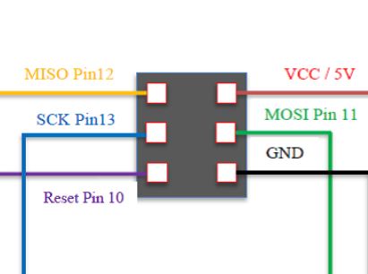
you may ask why using the ISP pins for this test, in I2C newtwork, simple put, the the pins for the pcb I am using already has some taken pins for the pushbutton and led build in the pcb. this pcb is the one from week 6 'electronics design ' and I am using 2 of it to make the communications...and for that, almost all pins are used, so after I uplaoded the porgarm to the pcbs using ISP pins, using the arduino , I took ISP pins off and use them for the newtowrk between the 2 attinys
check the video to understand how it works:
Now, lets try the last way of communication using RX and TX pins from attiny44, I will connect 2 attiny 44 between eachother using GND to GND, 5V to 5V form sender to resiver pcb, and finally, connect TX from the sender to RX in the reciver and send data by using 2 inputsfrom the sender(pushbutton and IR proximity sensor) with 3 conditions:
check the video to understand how it works:
this communication method will be used in the final project to connect between the chair and the desk
see the code of the sender here:
  //new  send 11L


#include// serial library

int bp = 3;// declare that bp(pushbutton)is in pin 3
#define LED A7
#define prox A1

SoftwareSerial myserial(1, 0); // define the serial and the TX=1 and RX=0

void setup() {
  pinMode(bp,INPUT_PULLUP) ;// Declare that pudhbutton is an input
    pinMode(prox,INPUT_PULLUP) ;// Declare that pudhbutton is an input

  pinMode(LED, OUTPUT);


  myserial.begin(9600);
}

void loop() {

  int bps = 0;
  int proxs = 0;

  bps = digitalRead(bp);
    proxs = digitalRead(prox);

  if ((bps == LOW)&&(proxs == LOW)) //if the pushbutton is pressed this condition will be true
  {

    myserial.write('1');// send this char
           digitalWrite(LED,LOW);


  }
  else if ((bps == LOW)&&(proxs == LOW))
  { myserial.write('2');//if the pushbutton is not pressed sen this char
            digitalWrite(LED,HIGH);
              delay(10);
              digitalWrite(LED,LOW);
delay(10);
digitalWrite(LED,HIGH);
              delay(10);
              digitalWrite(LED,LOW);
delay(10);
digitalWrite(LED,HIGH);
              delay(10);
              digitalWrite(LED,LOW);
delay(10);

  }
else{
  myserial.write('0');
  }
  delay(100);

}
and the code of the reciver here:
//new recive 6R #includeThank youint led = 7;// declaring the LED pin char ON = '1'; //declaring that ONturnon is the char the will be recived. SoftwareSerial myserial(1, 0); void setup() { myserial.begin(9600); pinMode(led, OUTPUT); digitalWrite(led, HIGH); delay(100); digitalWrite(led, LOW); } void loop() { int chr = myserial.read();// chr will be equal to which the derial will read if (chr == 1) {// if the chr have the same value of ON, the LED will be ON. digitalWrite(led, HIGH); delay(100); } else if (chr == 2) { digitalWrite(led,HIGH); delay(10); digitalWrite(led,LOW); delay(10); digitalWrite(led,HIGH); delay(10); digitalWrite(led,LOW); delay(10); } else{ digitalWrite(led,LOW); } }