Group Assignment:
1) Characterize the design rules for your PCB production process
Individual Assignment:
1) Make an in-circuit programmer by milling and stuffing the PCB,
test it, then optionally try other PCB processes
The documentation of the intial processes of the approach to the milling machine and the design rules of my PCB are available at this link.
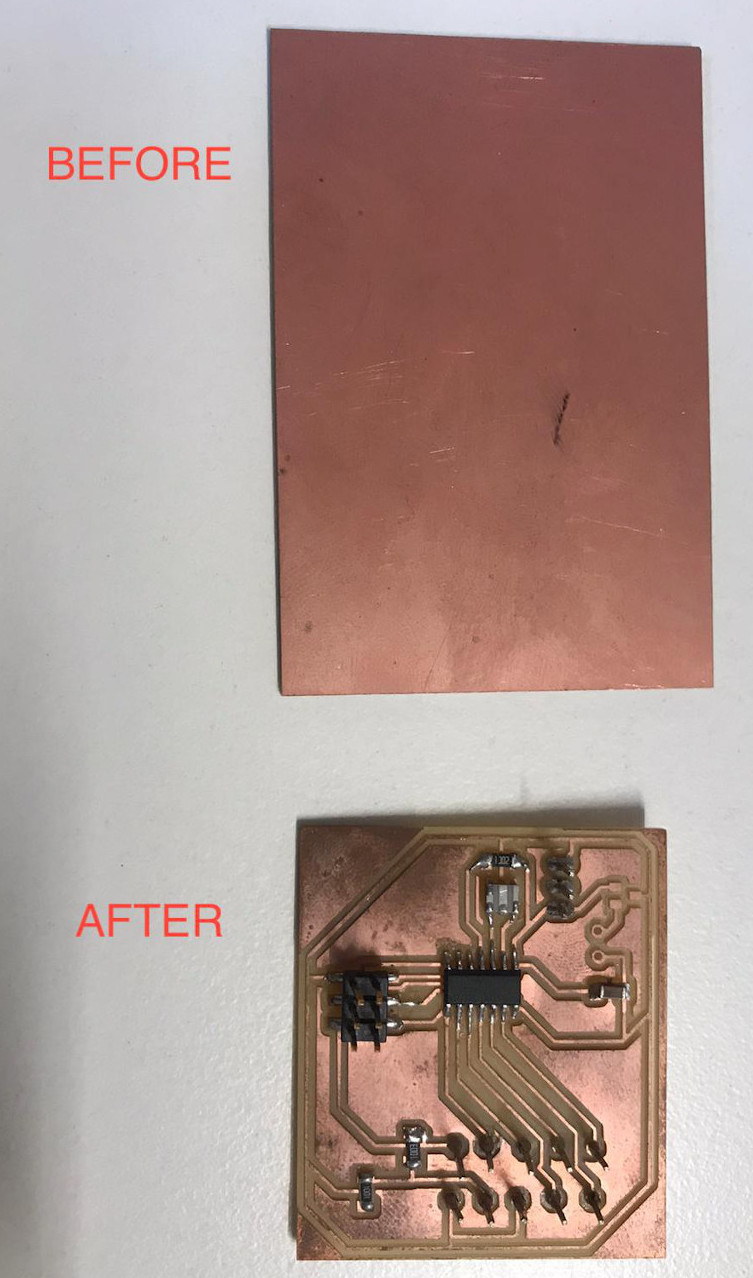
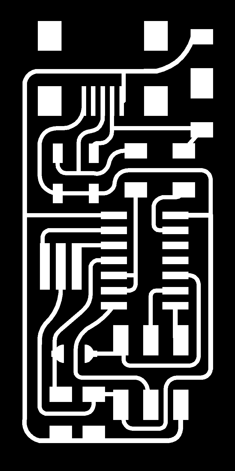
During this week I'll make a FR1 PCB on copper using a Roland SRM-20 and I'll learn how to solder it's components. This is what I'm expecting to have at the end of the week:
First things first, following the instructions of my instructor, I went on this page to download the files of the traces and the outlines .Once I got the pngs I opened mods and I clicked on "select a new png file".
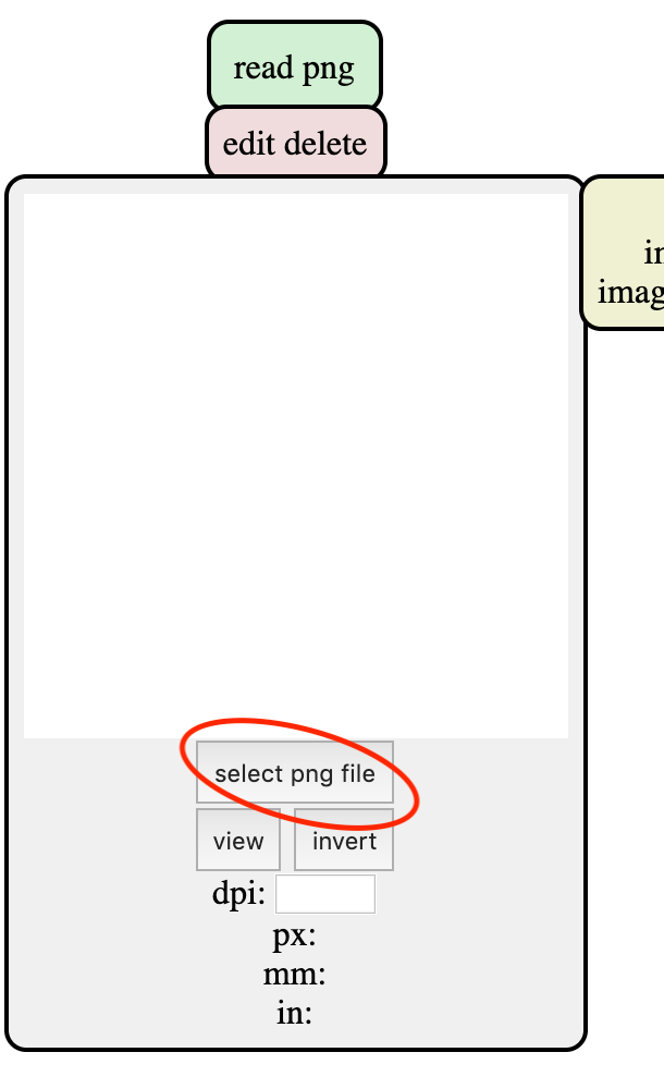
This way I was able to select my traces file. In the next mod I could choose the type of file between traces and outline.
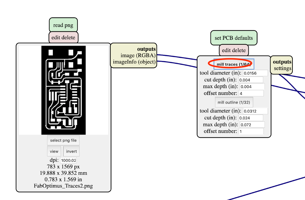
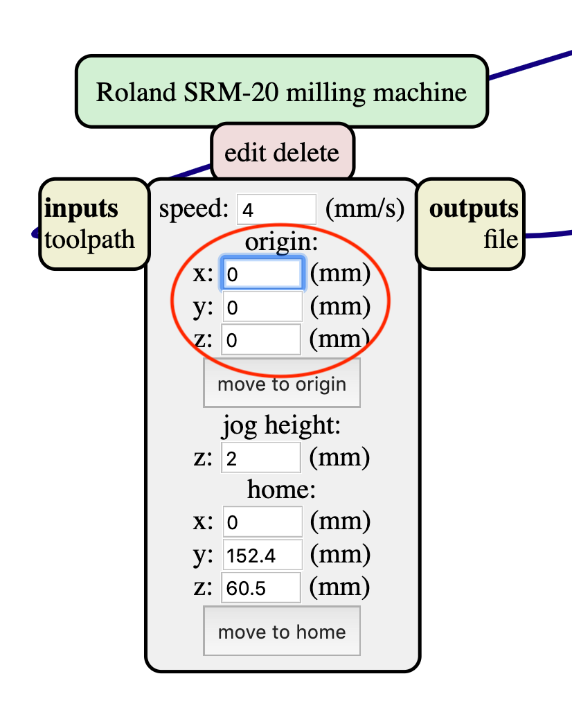
Automatically all the settings will be in the mods. The only thing I had to change was in the block right under the first one: set the origin to X:0, Y:0 and Z:0.
At this point, next to this last mod I had the chance to send my file directy to the milling machine but I rather prefer to save it. So I've deleted the mod that I didn't want and back to the right upper corner, right click and add a "file save" mod.
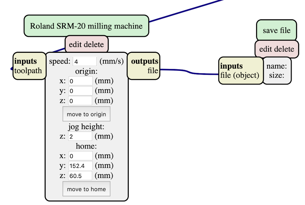
I still had to link the new mod and I did it by clicking firstly on the output button of the origin mod and then on the input button of the save file mod. Now my new save file mod is connected to all the diagram and I can save the rml traces file by clicking "calculate" on the settings mod:
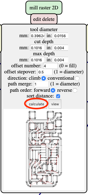
I've done this procedure with the outilines file aswell and now I'm ready to send my file to the milling machine. I have documented the initial procedures in the group repository at this link.
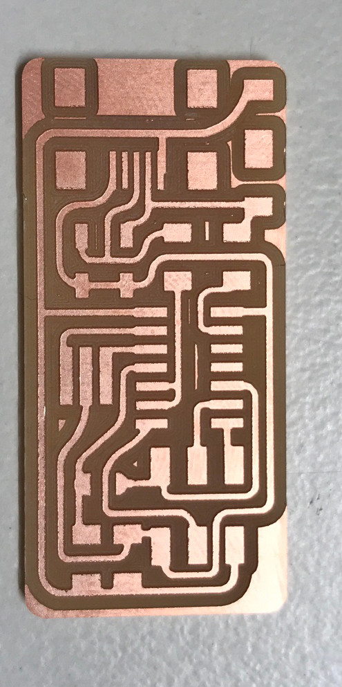
After the milling this is my result:
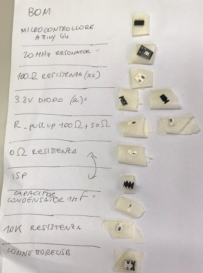
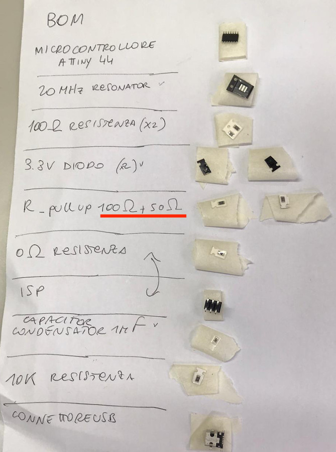
The first thing I did before starting the soldering process was to make a BOM (Bill Of Materials) in order to be sure to collect all the right and necessary componets to be soldered on my board:
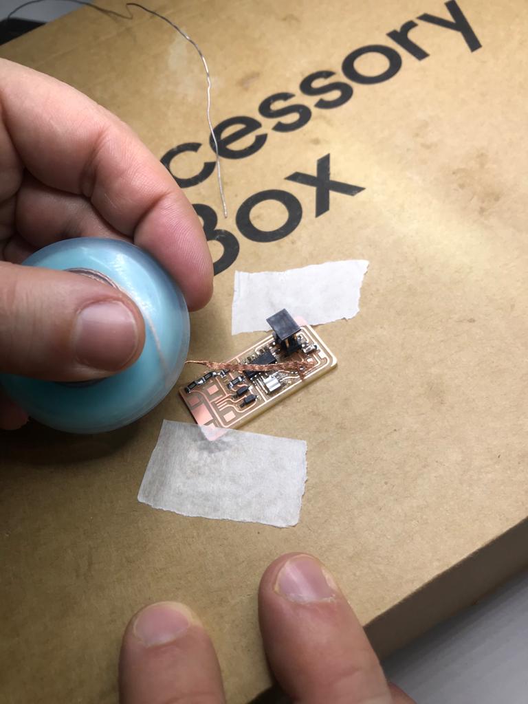
1) Place your board on a solid surface on which you find yourself confident and tape it on the corners.
2) Apply a very small amount of flux on the surface on which your component will sit.
3) Set your component in the right position using a pair of tweezers.
4) Deposite solder on the tip of the soldering iron and apply a drop between the copper trace and the component.
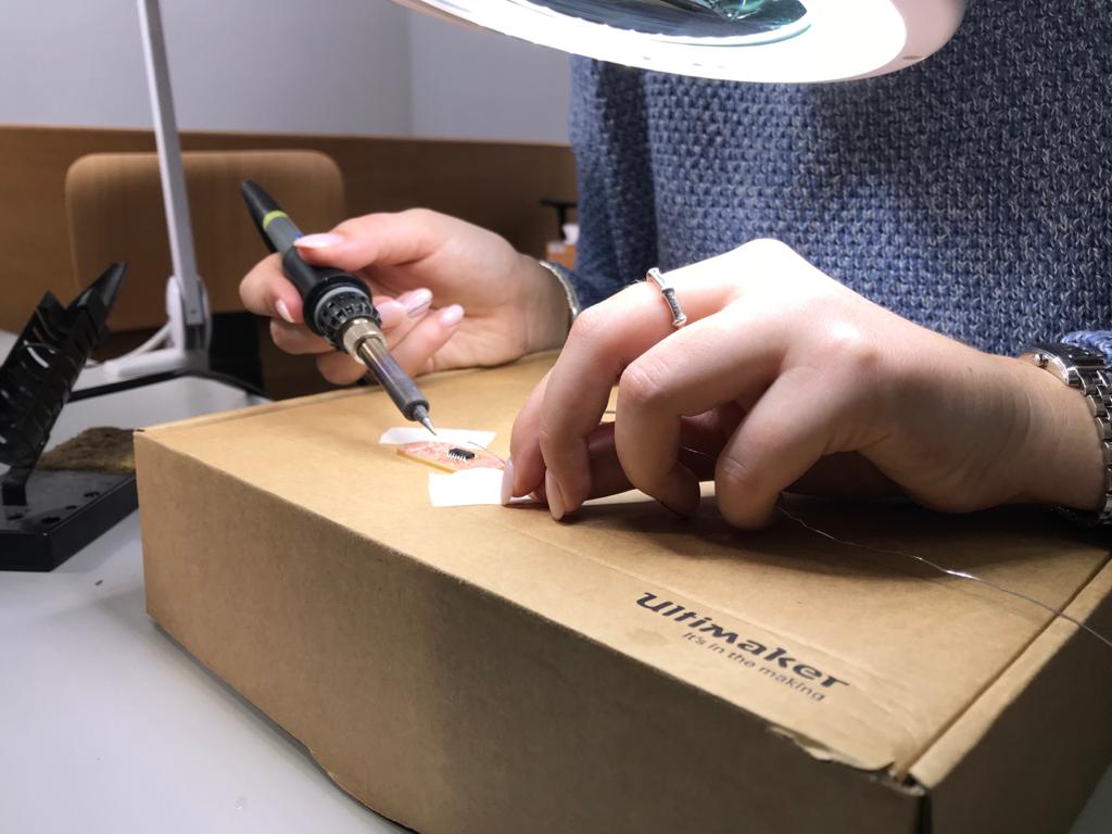
I started soldering from the microcontroller, as I wrote my BOM in a chronological order, and went on following a outward spiral pattern. So This is what I have now:

Looks nice right? It's not. I have made a few mistakes here.

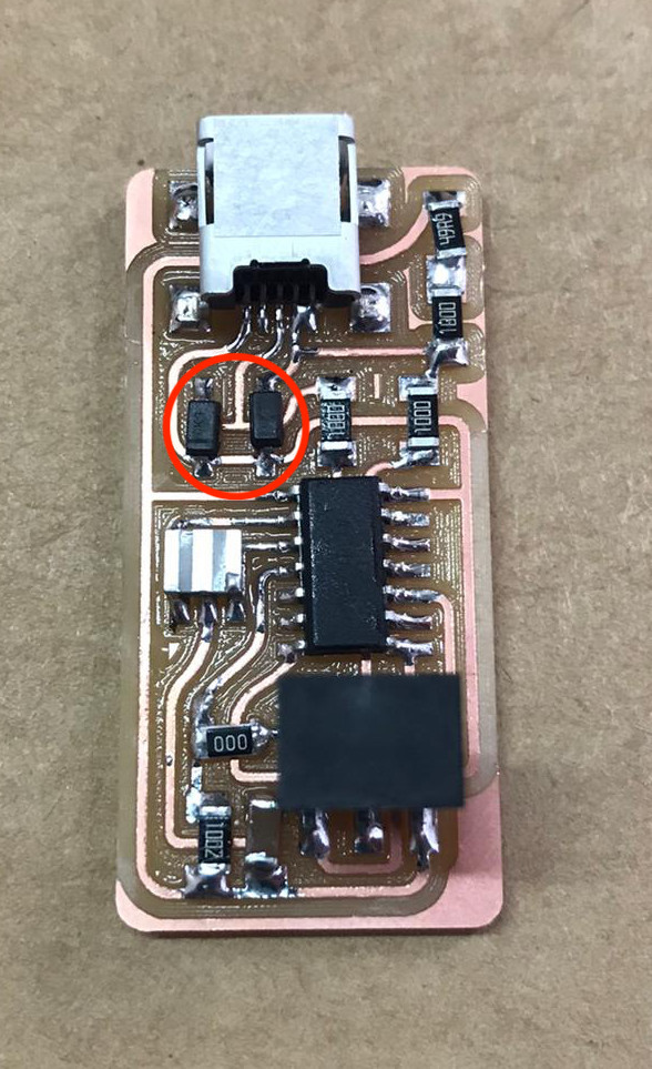
A small line indicates the cathode on diodes so I realized that mine were soldered the wrong way round. This lead me to the desoldering part.
I have whatched this tutorial video which was very helpfull to go through all the steps of soldering and desoldering. Solder bridges can be fixed by using the copper braid or just the soldering iron. To use the copper braid you need to position it on the part you want to remove and place the soldering iron on top of it, so that the braid will absorb the excess of solder. Otherways you can remove a component by using the iron on both sides of the component itself so that the solder will melt again and let you remove the component using a pair of tweezers.
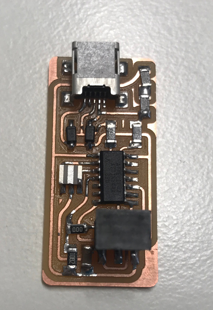
I used both the copper braid and the soldering iron to fix my mistakes and I got to this result :
Now that my board "looks" good I tried first of all the so called Smoke test. So I connected my board to the pc with a cable and nothing strange happened, I didn't get any warning advices. My board passed the smoke test luckly.
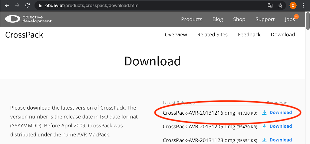
The second thing to is try to programme the board. As a first thing I had to download AVR CrossPack.
Following the tutorial guide I downloaded the firmware:
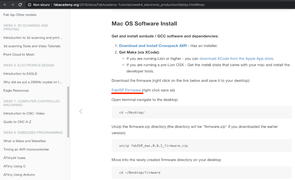
The right click command didn't work so I tried to left click on the link and I've downloaded the file
directly from GitHub.
Following the instructions on the guide, I unzipped the file from my shell.
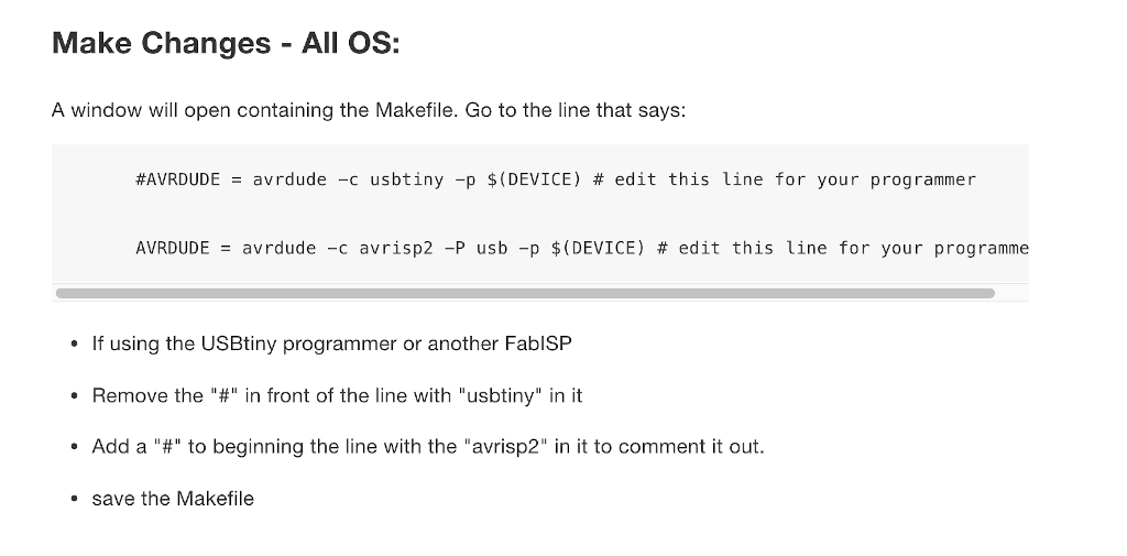
I had to edit the file named "Makefile" on my editor:
I then had to compile the firmware. So I connected a functioning board (programmer) to my computer and, usign some jumpers, I connected my board (programmee) to start the programming fase. Unfortunatelly my pc didn't see my board (programmee).
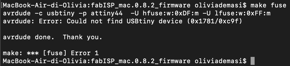
So as a first thing I checked the plugs and the cable (using the multimeter), and everything worked properly. So I tried to connect the programmer and my board to another computer and I found out that it is recognized so I was able to program it following the guide's commands "make clean" "make hex" "make fuse" "make program".
Although the programming fase was possible on a Linux OS pc any other pc wouldn't recognize the the board. So something was still wrong and I had to try to debug it.
Looking around on some documentation I decided to try to take out the 0 ohm resistor straight away and check if the pc would have recognized the pcb. Nope. After a few hours and several shots at the possibile problems, with the help of my instructor, I found out that I soldered the wrong resistors.
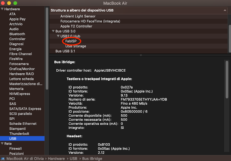
It was a very silly mistake because I should have solder a 1K resistor and a 0.5K one. So I desoldered the wrong resistors and put in the right ones. I tried my board again and this time it is recognized like a FabISP (yay):
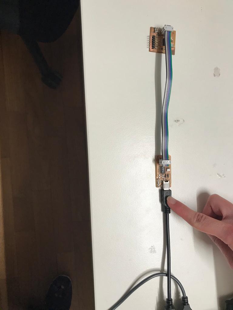
But unfortunatelly it doesn't work as a programmer. So as a litmus test I have resoldered the 0 ohm resistor and I have tried to reprogram it and it worked! The pc recognized it as a FabISP. The only test left to do is to try using my board as a programmer. So I connected it to my pc and, using a ribbon cable, I connected it to a hello board from last year's Fab Academy:
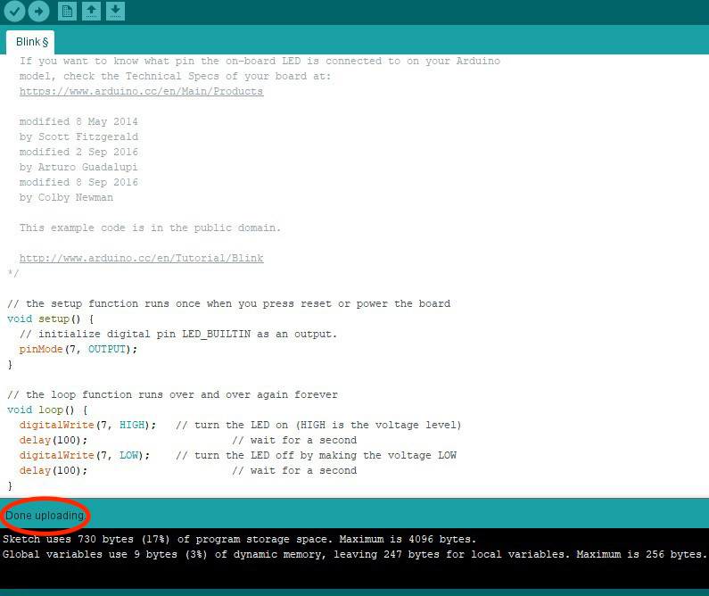
Exceptionally I used Arduino 1.8.5 on my colleague's pc because I didn't know how to program the hello board (I'm pretty sure I'm going to learn how to do it in Electronics design week) and I didn't have any other boards available for testing. So my instructor downloaded the Arduino IDE, he added the Attiny 44 support, he wrote a code line to make the led of the hello board blink, and finally, loaded it on the hello board through my programmer. The upload went well so that means my programmer works:
I flowlessly used my PCB in the following weeks:
- Electronics Desing;
- Output Devices;
- Machine building week;
- Project Developement;
- FabOptimus_Traces2
- FabOptimus_Outline2
- https://www.youtube.com/watch?v=3NN7UGWYmBY