Week 6: Electronics Design
Group Assignment:
1)Use the test equipment in your lab to observe the operation
of a microcontroller circuit board.
Individual Assignments:
1) Redraw an echo hello-world board,
add (at least) a button and LED (with current-limiting resistor)
check the design rules, make it, and test it
extra credit: simulate its operation.
GROUP ASSIGNMENT
The documentation of the test equipment to observe the operation of a microcontroller circuit board is available at this link.
INDIVIDUAL ASSIGNMENT
Eagle - Add libraries
I decided to try Eagle as a design software. So I downloaded it from my browser (Mac OS version) and then
I had to download the fab library (at this link ) to add to Eagle with all the components that I needed in it. It was not so easy for me
to understand how to make it work, so I followed this tutorial guide and followed the steps:
1) unzip the library folder you have downloaded and double click on "fab.lbr"
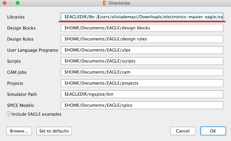
2) when Eagle opens click on "options" in the upper toolbar - "directories" - and change the path with the right one of your local eagle folder (I followed the guide mentioned above for this part)
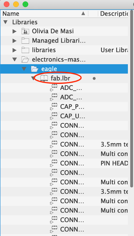
3) now your library should be visible in the library section:
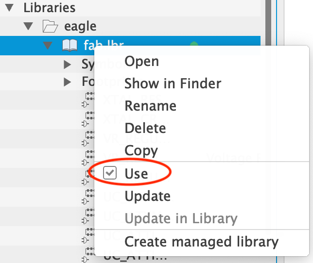
4) to be sure that the library will be available in your project files, right click on "fab.lbr" as select "use":
Eagle - Attiny 45 Schematic
I've seen how the design sofware works by watching my instructor using it to design a PCB. So the first thing I did was to create a new project on Eagle from which I opened a new schematic file. I started to insert the component watching the schematic that Professor Neil uploaded on the schedule:
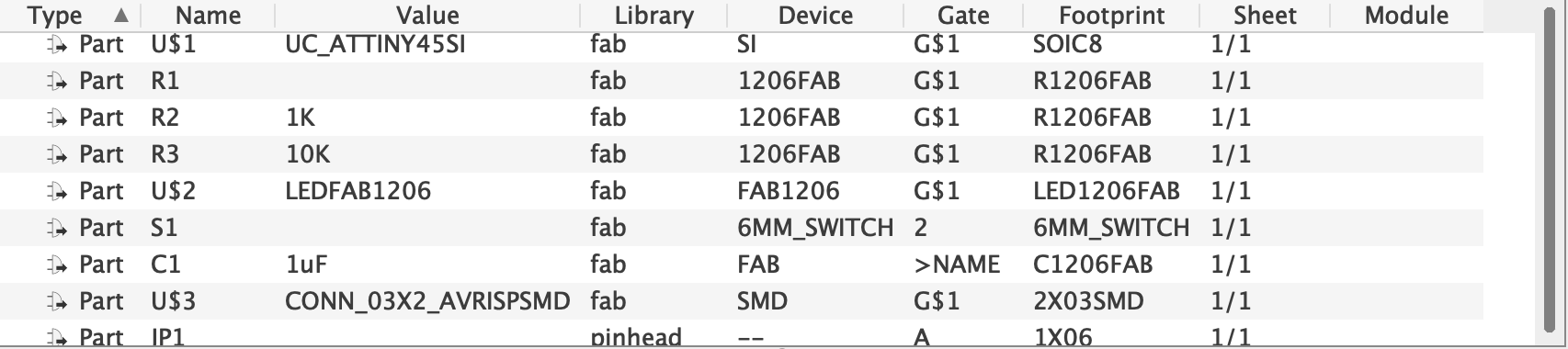
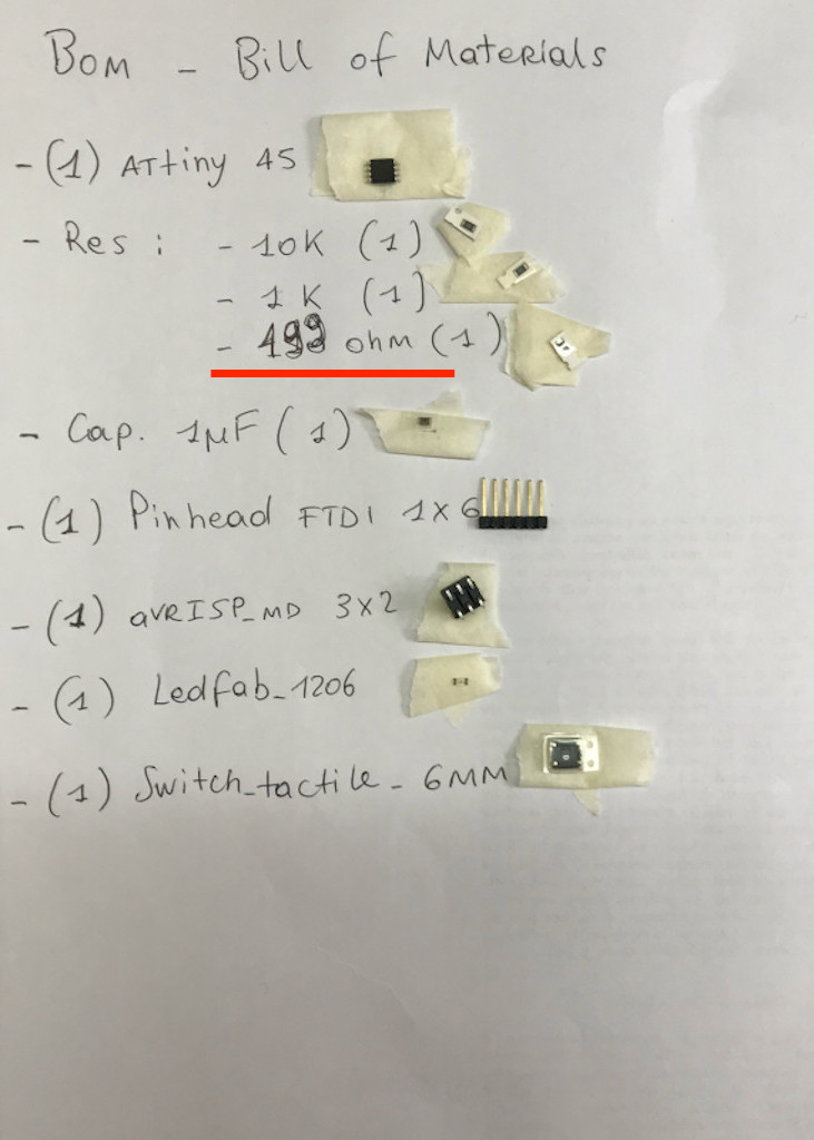
I've added, as required from the assignment, a switch button, a LED and a resistor. To now the value of the resistor I used this link and found out that for the color of the LED that I chose I needed a 150 ohm resistor. So this is the list of my components:
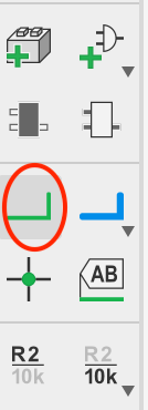
After I inserted all of the components in my worksheet I had to connect them between eachother logically using the "net" tool.
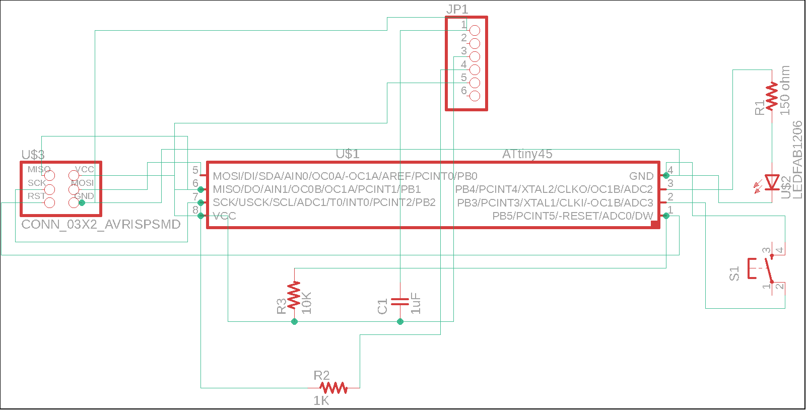
This is what my schematic looks like (it's a bit messy I know):
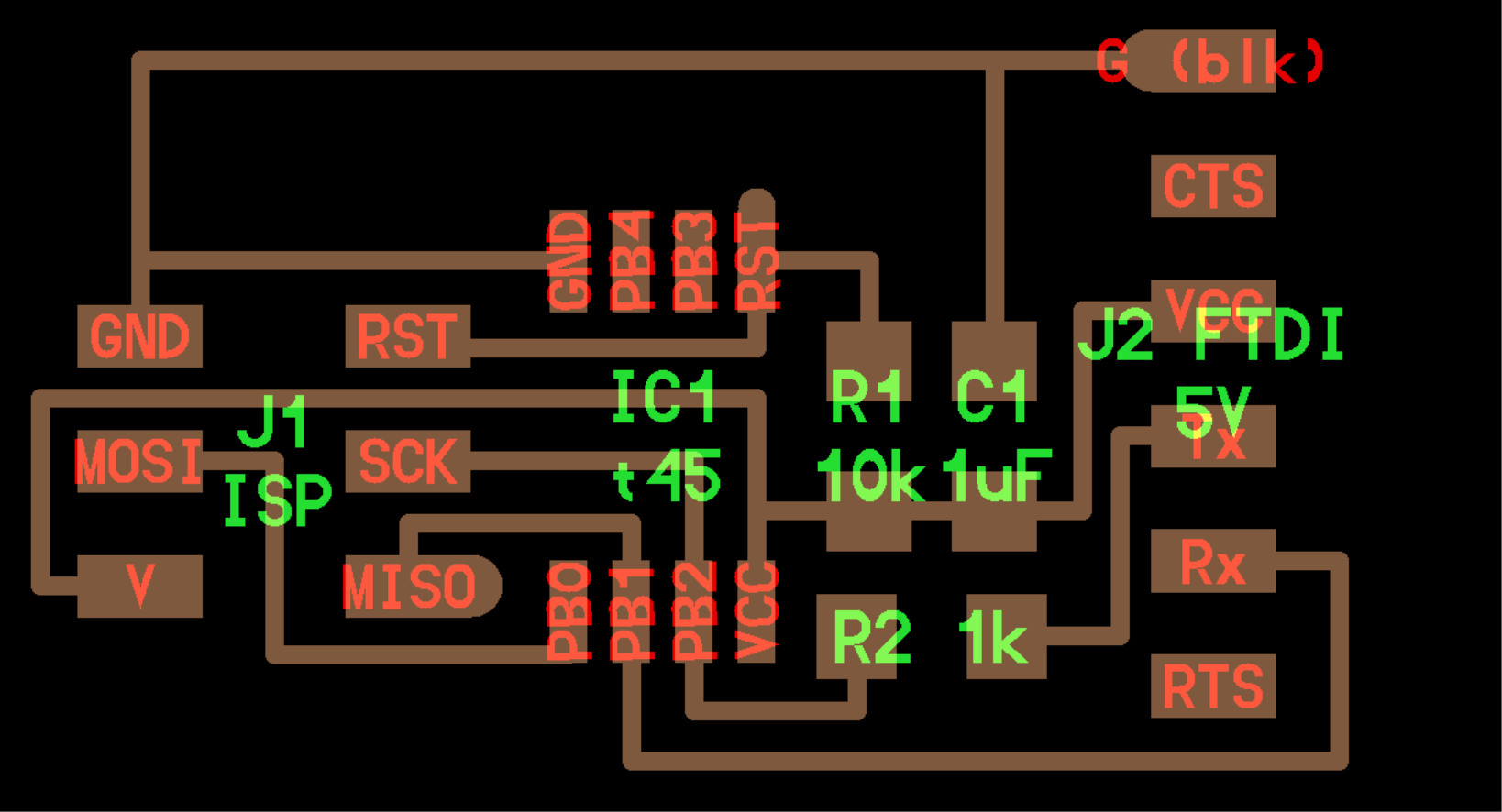
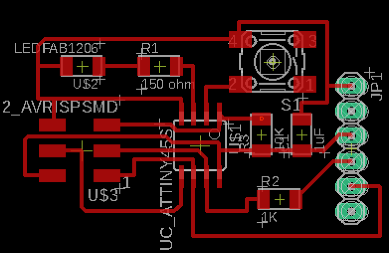
This is where things got harder for me, because I had to pass to the routing process in a new .brd worksheet. The first time I tried to move around the components to save as much space as I possibly could but things got really messy the moment I started routing so I eventually decided to follow Professor Neil's exact same routing path and add on the upper left corner my new components. So I started routing and I'm quite happy with my result:
I exported the png file and import it on Gimp to make it adequate for the mods. So I exported it as a monochrome .png file with 1000 dpi. On Gimp I had to add 100 px to the canva to make the file for the outlines and I had to isolate the black buttons of the pinhead to make an extra file for the holes. No trouble with that.
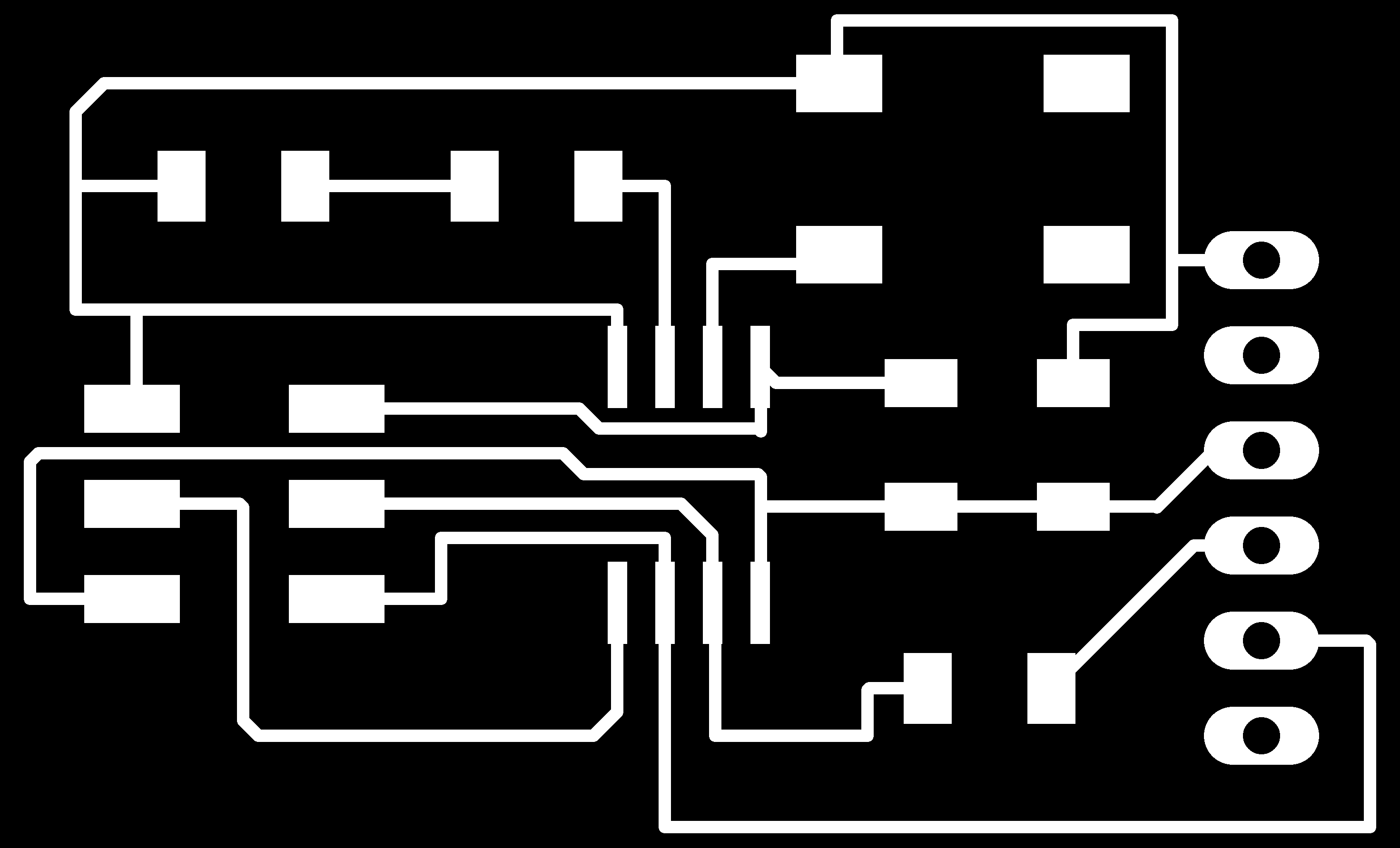

I put the png files on mods and I had no problem with the traces and the outlines:
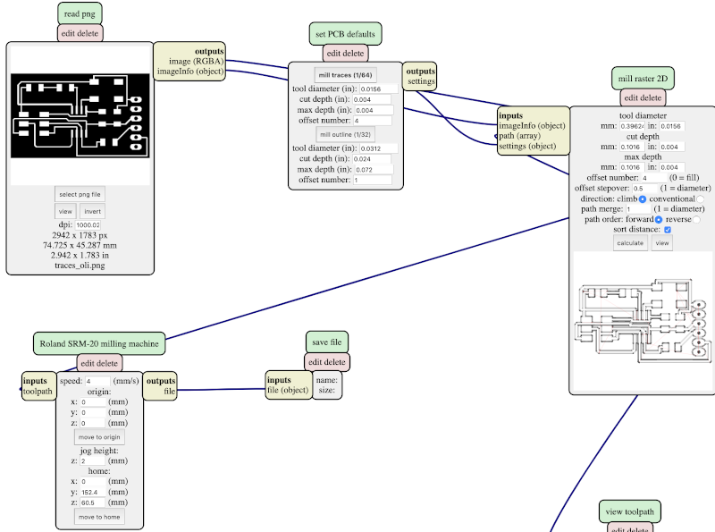
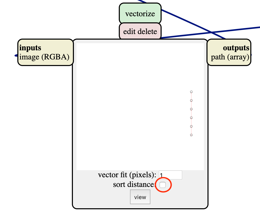
The mistery appeared when I uploaded the holes (for the pinhead) png file, infact mods wouldn't calculate the milling process. After many many tests no results came up. I had no idea why this type of png wasn't being processed. One of my instructors, Flavio, suggested to try to use the old Fab Modules and it actually worked! In the mean time my other instructor, Simone, kept trying to solve the mistery. After a bit he found out the reason: the "sort distance" tick that I show in the picture below of the "vectorize" module, needs to be UNTICKED.
When the mistery was finally solved, I could send the files to the milling machine and mill the traces, then the holes and at last the outlines of my new PCB.
Attiny 45 - Milling and Soldering
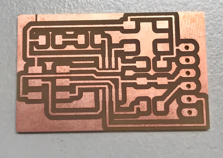
After milling my board I checked that all the traces were made as they were supposed to be. Then I completed my BOM picking all the components I needed. I had to change the value of the LED resistor because the lab didn't have the 150 ohm one, so my instructor told me to use a 500 ohm resistor:
So I soldered my PCB, following an outward pattern from the Attiny45 as I did the first time, and this is the result:
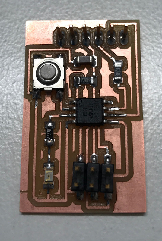
Far from all my expectations the board worked, after a little solder adjustment on the ISP, and was programmed:
Attiny 412 - Schematic
I wanted to excercise more on Eagle so I decided to try out the Attiny412 board:
I started adding the components to my new schematic but when I got to the Attiny412 microcontroller I had some trouble finding it. So I decided to add some new libraries: SparkFun and Adafruit. Now I'm stuck at this point:
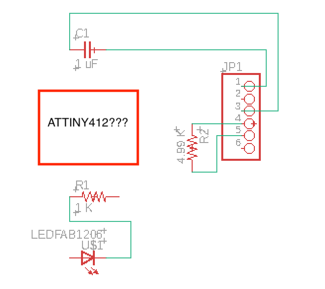
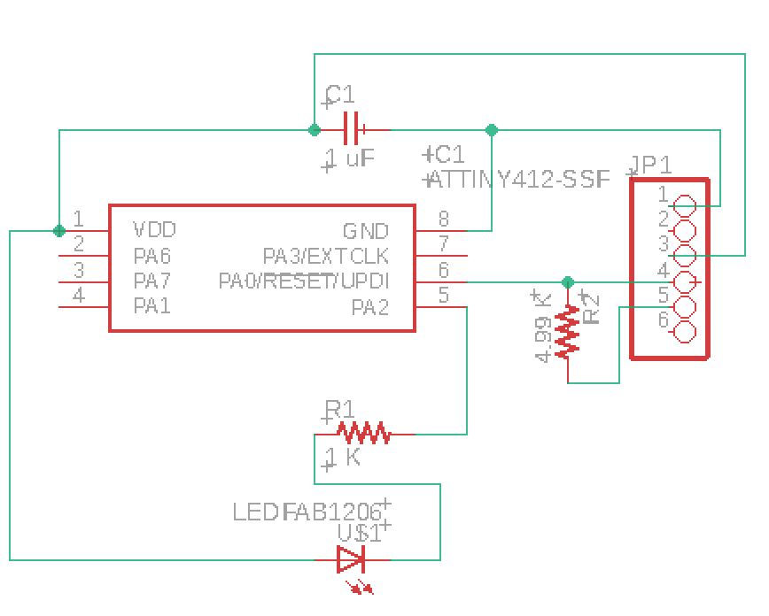
With the help of my instructor I got the Attiny412 finally so I can keep on working on Eagle and finish my schematic. Following there is the list of the componets I used:
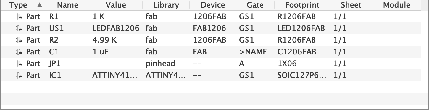
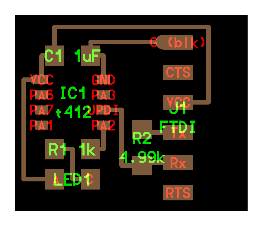
And this are the final schematic and the routing:
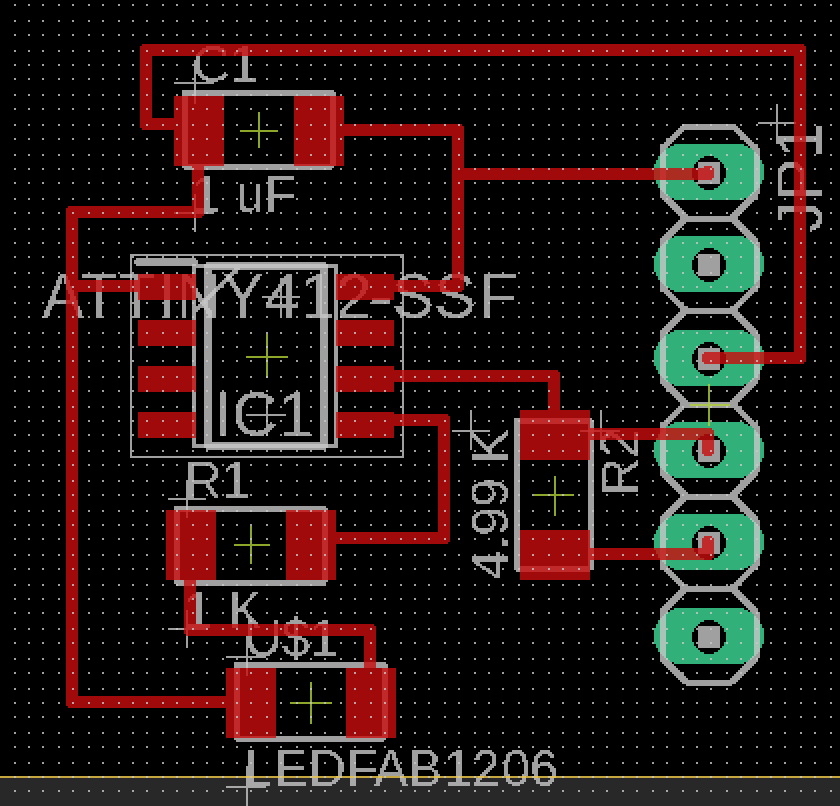
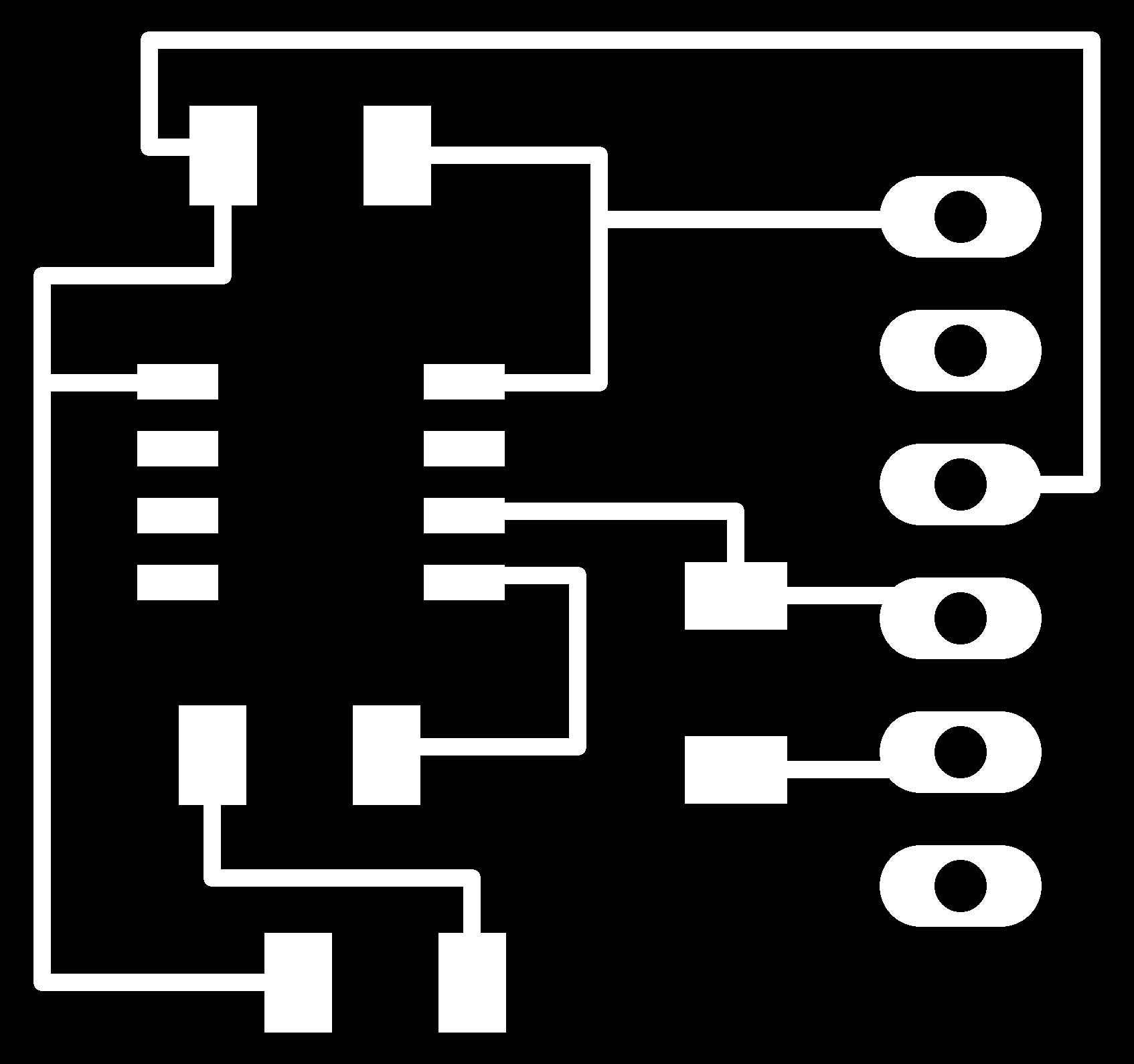
To keep on practicing I exported the png file and impoted it on Gimp to make the files for the mods. Unfortunatelly I won't be able to mill this board because the lab has closed due to Coronavirus.

Links
- http://fabacademy.org/2020/labs/santachiara/06.html
- http://led.linear1.org/1led.wiz
-
Improvements
- I'm going to try out Kicad.
- I want to make an Attiny1614.
Downloads
Attiny45:
- board
- components
- traces
- outlines
My files:
- Eagle files