Week 8: Embedded Programming
Group Assignment:
1) Compare the performance and development workflows
for other architectures.
Individual Assignments:
1)Read a microcontroller data sheet.
2)Program your board to do something,
with as many different programming languages
and programming environments as possible.
GROUP ASSIGNMENT
Me and my collegues were not able to complete this week's group assignment due to Coronavirus.
INDIVIDUAL ASSIGNMENT
AVR - The Toolchain
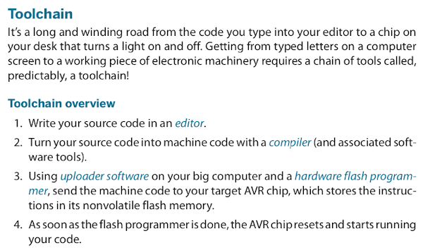
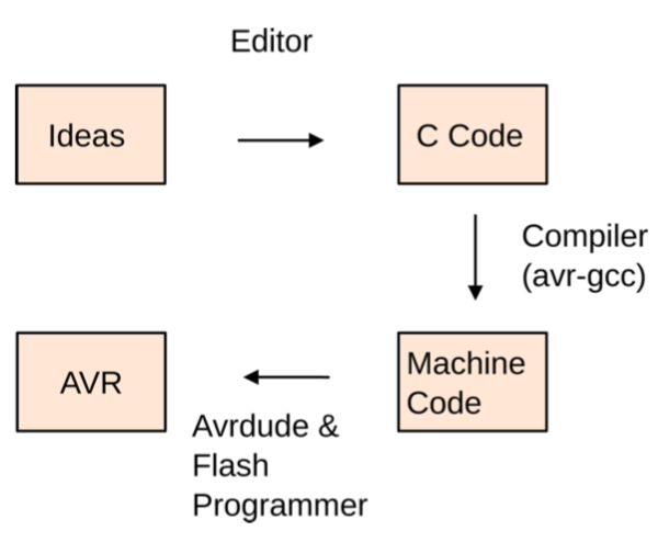
Having no knowledge at all about programming my instructor suggested me to read a very helpfull book: Make: AVR programming. The first chapter is basically on overview of what a microcontroller is and does. From the second chapter I learned what the toolchain is:
Following the first step I choose Atom because is the editor I usually use. Now I just have to learn something about C language, here are some tutorials I looked up:
- The C Preprocessor- AVR Tutorial: how to acces Input/Output Ports
- Tutorial: writing your first AVR C program - blinking LED
Basic C structure
Preamble:
list of libraries for which you need an #include.
Main function:
it's the part of the code in which you include all of the instructions that the microcontroller must execute. E.g. "int main ()", where "int" stands for integrate number.
Variables:
right after the preamble you can right the variables code. E.g. "int a=1; int b=2".
Flow control:
IF -> if something happens then something else must happen, it's a condition to be verified. E.g "if (x==5)", then the instructions in the "main" must be executed.
FOR -> it's a code line to execute an instruction a certain number of times, it's a repetition condition. E.g. "for (int x=0; x<10 x++)" where the firts it's the variable, the second means that
the operation must be performed for 10 times and x++ means that I want the x's to be added one at the time.
WHILE -> execute an instruction untill something happens, it's a condition always verified. E.g. "while (true)". If after that you wrigth a blinking LED code you'll end up with a loop.
Hardware register
DDRx (Port x):
Data-direction Registers. These registers control whether each pin is configured for input or output— the data direction. To enable a pin as output, you write a one to its slot in the DDR.
PORTx:
When the DDRx bits are set to one (output) for a given pin, the PORT register controls whether that pin is set to logic high or low. Switching between these voltage levels could, for instance, turn on and off attached LEDs.
PINx:
The PIN register addresses are where you read the digital voltage values for each pin that’s configured as input. Each PINx memory location is hooked up to a comparator circuit that detects whether the external voltage on that pin is high or low. You can’t write to them, so they’re not really memory, but you can read from the PINx registers like a normal variable in your code to see which pins have high and low voltages on them.
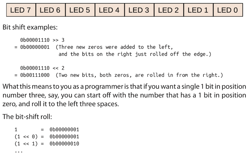
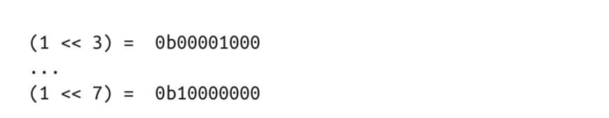
Bit twiddling
Bitwise logical operations—“bit twiddling”—lets us modify any one bit out of the register byte without having to think explicitly about the others. Instead of having to write out 0b00001000, I could just say “give me a number with a 1 in bit number three”? That way I could code the pins by incrementing or decrementing a variable and then putting a 1 in the corresponding bit’s place. The technique known as "bit shifting" will do exactly that. Bit shifts have the effect of rolling all the bits’ n positions to the left or right, depending on the command. Bits that fall off either end just disappear, and any new bits added are all zeros. The C language instruction for shifting all the bits in a number to the left or right is << or >>, respectively.
I then tried to understand the Attiny45's pins from the datasheet, because up to now I only knew VCC and GND:
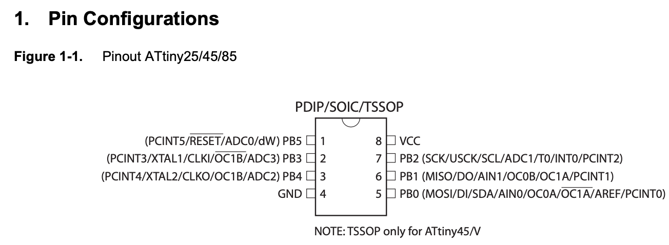
So:
- VCC= to supply voltage.
- GND= ground
- Port B (PB5-PB0)= are 6 bit bi-directional I/O ports. Input or Output ports.
- RST= reset input. A low level on this pin for longer than the minimum pulse lenght will generate a reset. It can also be used as a weak I/O pin.
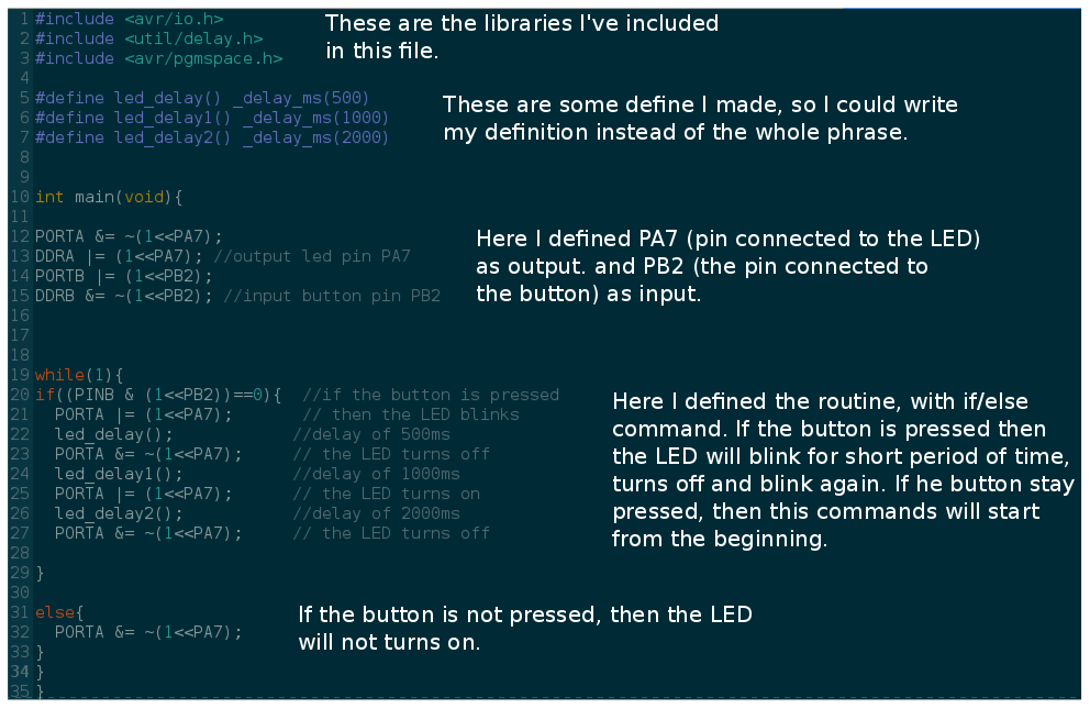
While I was looking through documetations from the prior years I found a well explained example of a blinking LED code from Flavio Lampus:
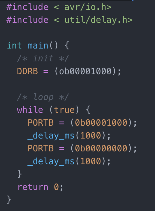
This are the fisrt C code lines I wrote:
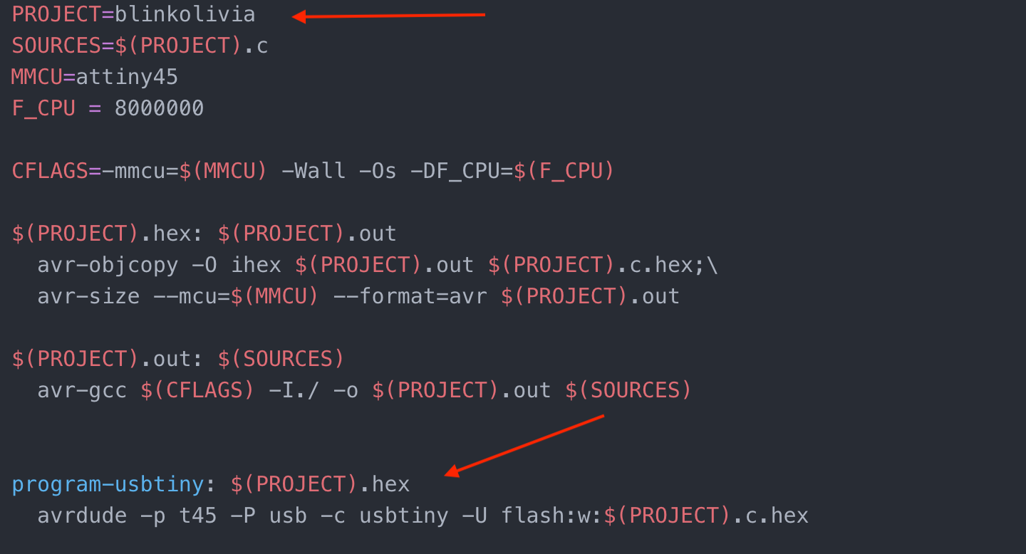
So I downloaded Neil's makefile for the Attiny45 and I edited adding the name of my c file, and choosing the program for the usbtiny:
I then added both files to a folder and, thinking that everything was fine I tried to compile using the shell of my computer. Unfortunatelly I didn't really get the meaning of the makefile and I tried to compile the c file first, this was actually very helpfull because it came out that I made a syntax error in the code:
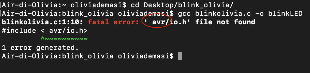
I had left a space between the quotation marks. So I fixed the problem and I tried again, mistaking again obviously because that was not what I had to do:
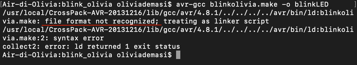
I went on the archive and found out everyone gave a "make -f" command, so I went back on my favourite book Make: AVR programming, and I went on my notes of the lesson and remembered that avr-gcc was already in the makefile so I just had to run the makefile, that's what it's for dah! So I gave the right command on my shell, and... I found out another mistake in the c file:
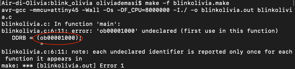
AAAAARRGGHHH. I put an "o" insted of a "0" in the code! Fixed the mistake, I finally got the right outcome:
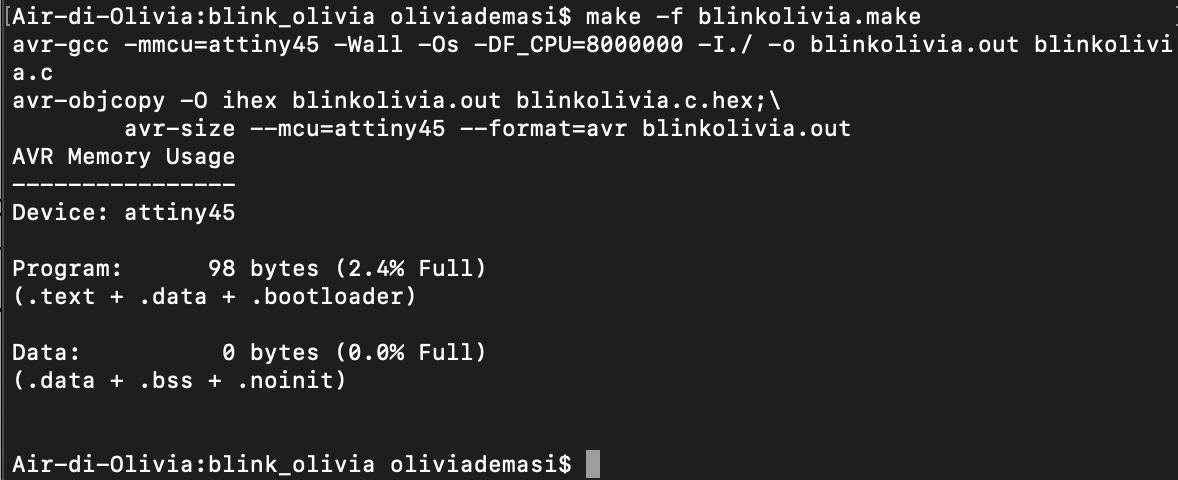
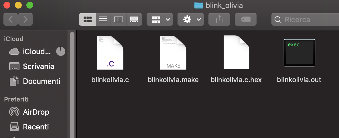
And two .c.hex - .out files were added to my folder:
The next step is to flah the software I wrote into the hello board. So I gave the comand "make -f blinkolivia.make program-usbtiny" but my computer's output makes me freak out:
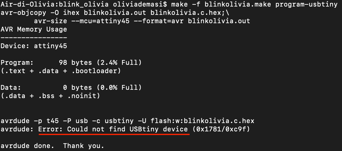
My computer dosen't recognize my usbtiny anymore.. So.. I don't have the possibility to get to the Lab to get another programmer due to Coronavirus, so I'm going to try everything out on another computer but my instructor says it may not work anyway because the programmer might be damaged or definitely dead. I hope not.
Links
- http://fabacademy.org/2020/labs/santachiara/06.html- https://gcc.gnu.org/onlinedocs/cpp/index.html#SEC_Contents
- http://ww1.microchip.com/downloads/en/DeviceDoc/Atmel-2586-AVR-8-bit-Microcontroller-ATtiny25-ATtiny45-ATtiny85_Datasheet.pdf
- https://www.elecrom.com/avr-tutorial-2-avr-input-output/
- http://www.toddholoubek.com/classes/pcomp/?page_id=692
- http://archive.fabacademy.org/archives/2016/fablabtoscana2016/students/129/embedded%20programming.html
Improvements
- I hope I'll get another programmer soon enough to complete the week.
- I want to try phyton.
Downloads
Attiny45:
- board
- components
- traces
- outlines