Week 11: Output Devices
Individual Assignments:
1) Add an output device to a microcontroller board you've designed, and program it to do something
INDIVIDUAL ASSIGNMENT
Buzzer
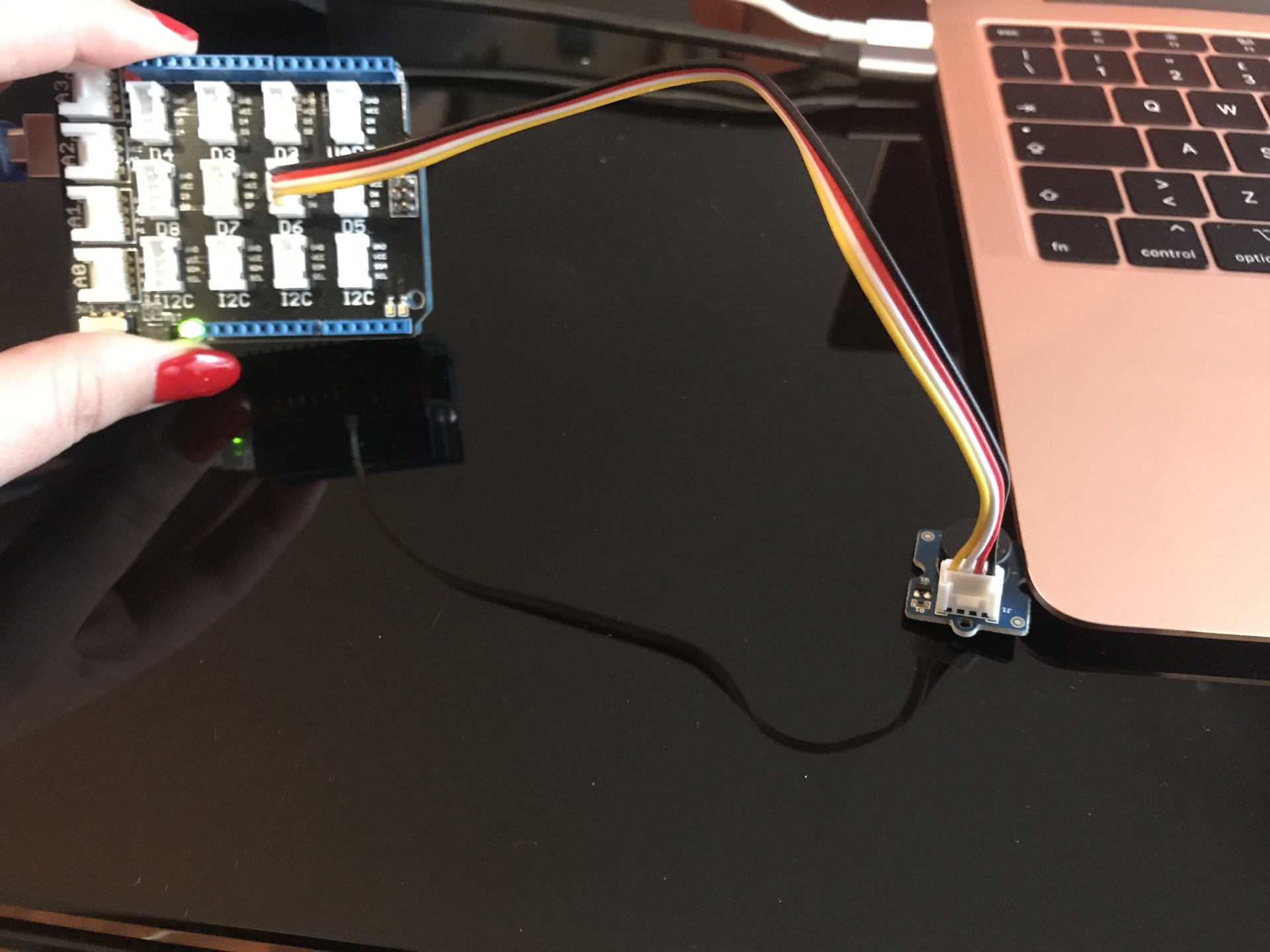
As I did for input week, I dug into my "magic sensor's box" and found a cool output sensor to try: a buzzer. So I followed the instructions on SeeedStudio and connected the buzzer to the Arduino board and the board to my computer.
I used the code that I found on SeeedStudio and copied it to Arduino IDE:
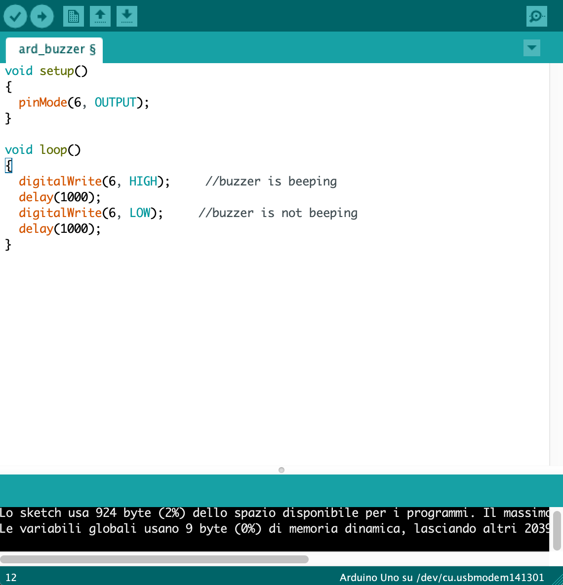
So the buzzer worked right away:
LCD Display
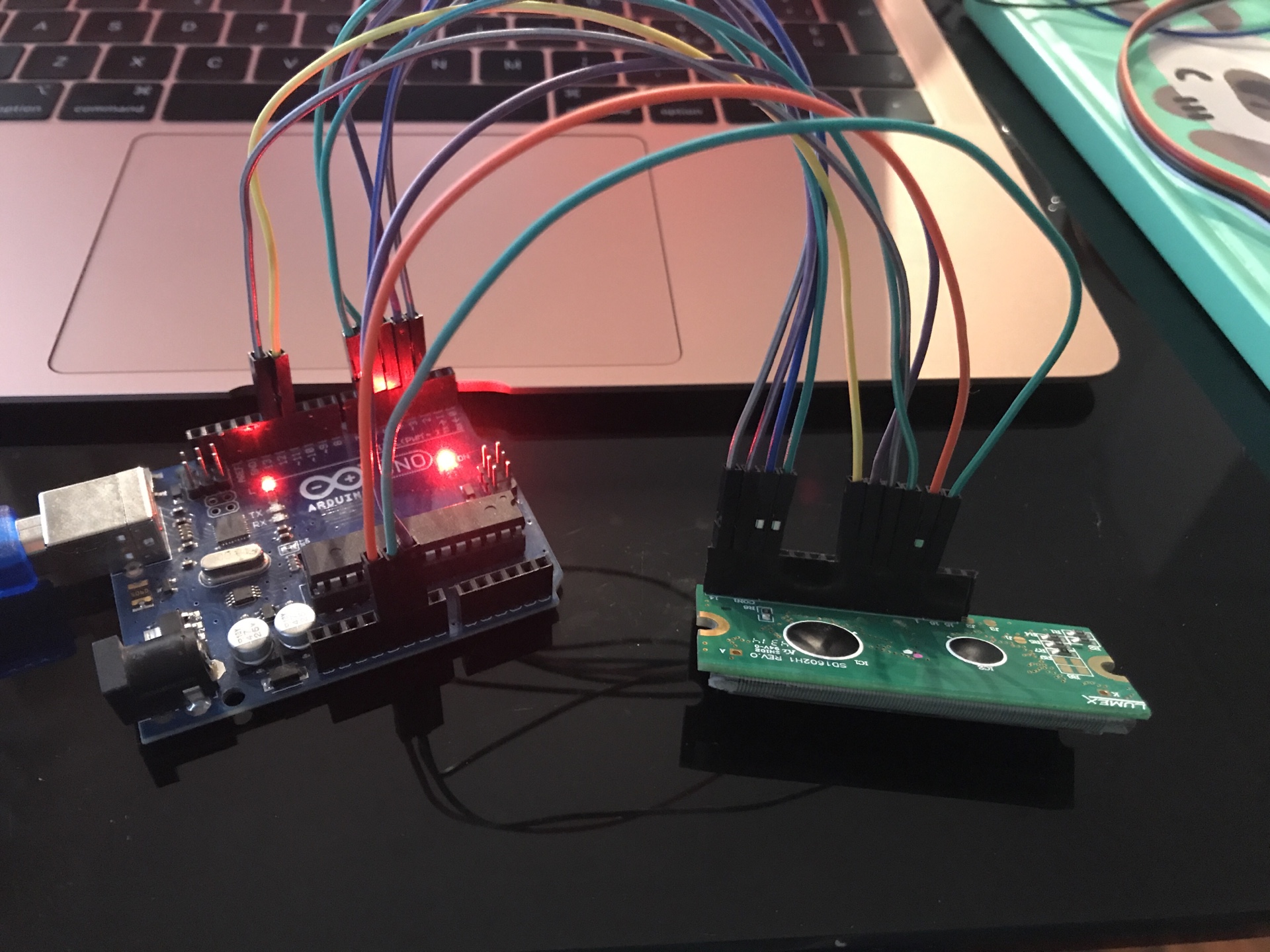
For the LCD Display I had to check the datasheet and the position of the pins.
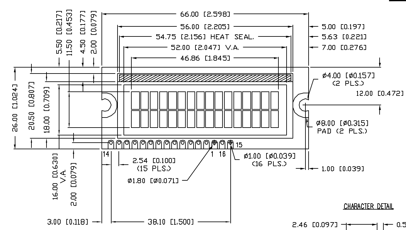
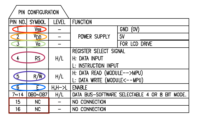
Following the instructions of this tutorial I was able to make all the connections between my Arduino (Uno) and the LCD leaving unconnected the pins 15 and 16.
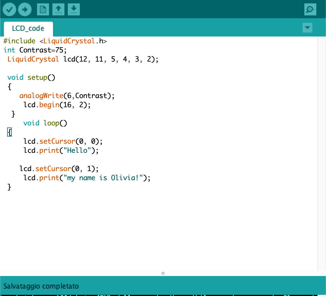
So I entered the code in Arduino IDE modifying the text that I wanted to appear in the LCD display "Hello" and "my name is Olivia" and this is the result:
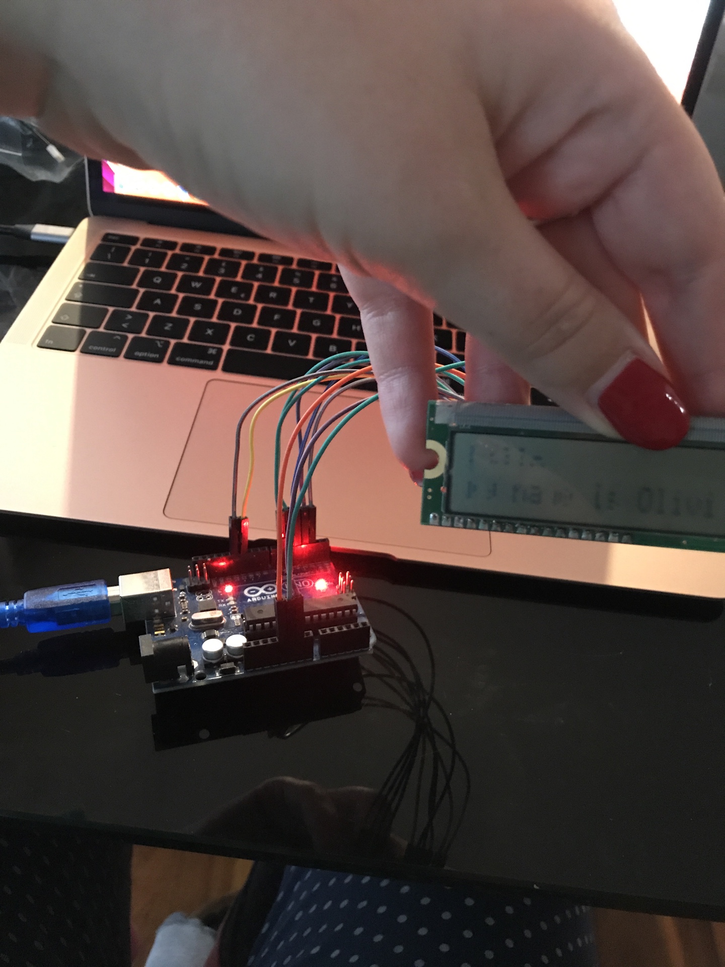
So this was the final result I got (it's a bit blurry but I think that's beacuse the LCD is old):
Tinkercad - Servo motor
I decided to use Tinkercad: a) to try it out, since I hadn't up to now and b) because I wanted to test a servo motor and I didn't have it in the kit
I received from my instructor. So I created a new project for a circuit and I placed an Arduino Uno R3 from the left side menu for a start.
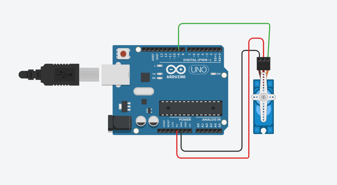
Then I follwed this tutorial on how to make a servo motor circuit. The components that I needed where:
- Servo Motor
- Arduino
About the connection:
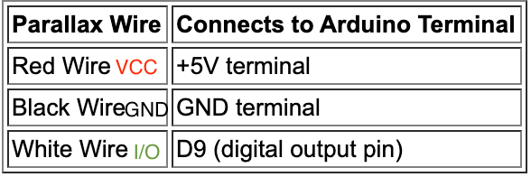
So I added a servo motor on Tinkercad and I made the connections:
I wrote the code I found in the tutorial that I mentioned before and I run it.
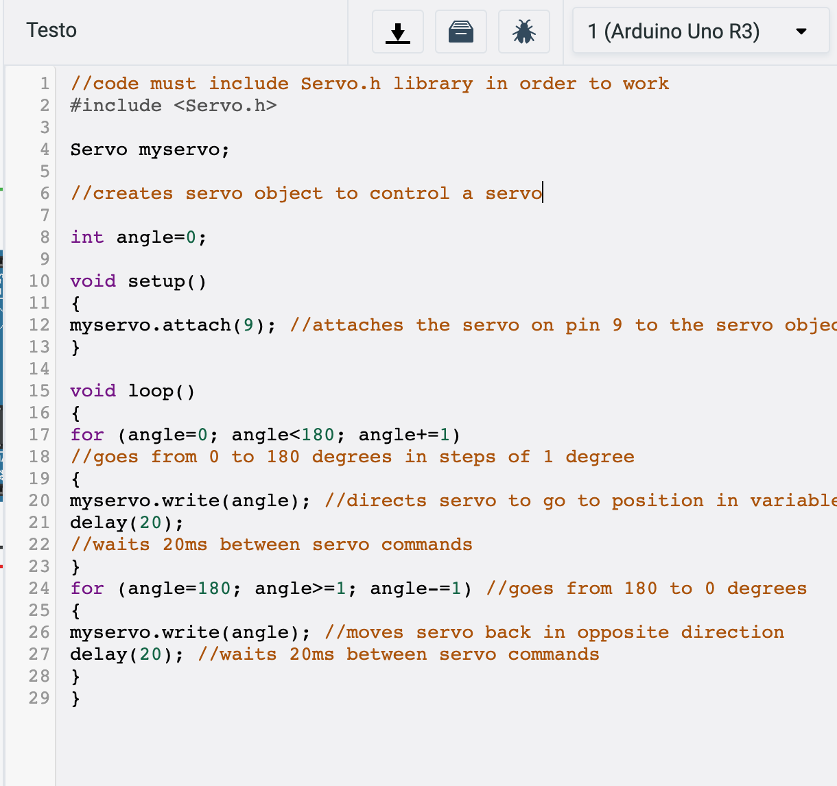
And this is the simulation of my servo motor:
simulazione_servo from Olivia De Masi on Vimeo.
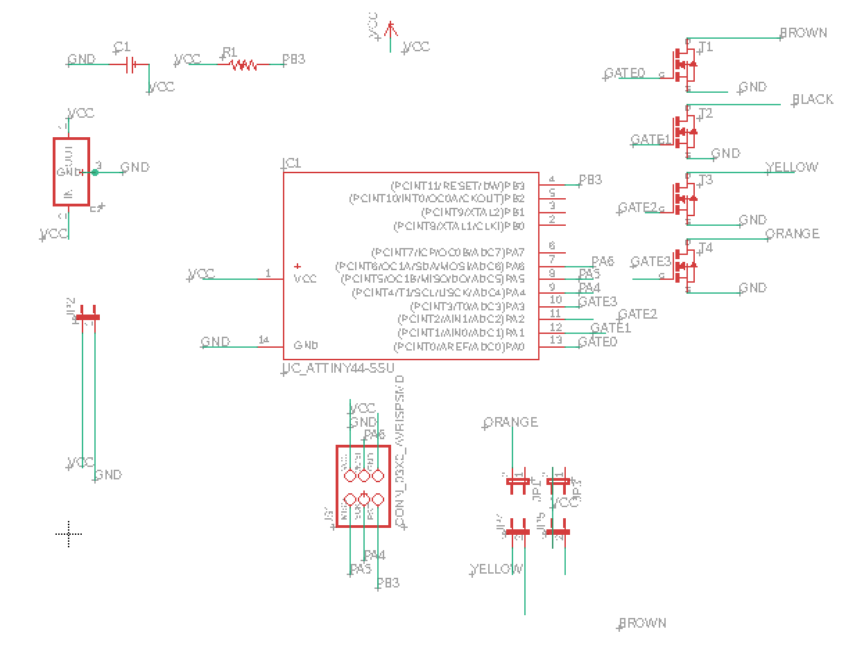
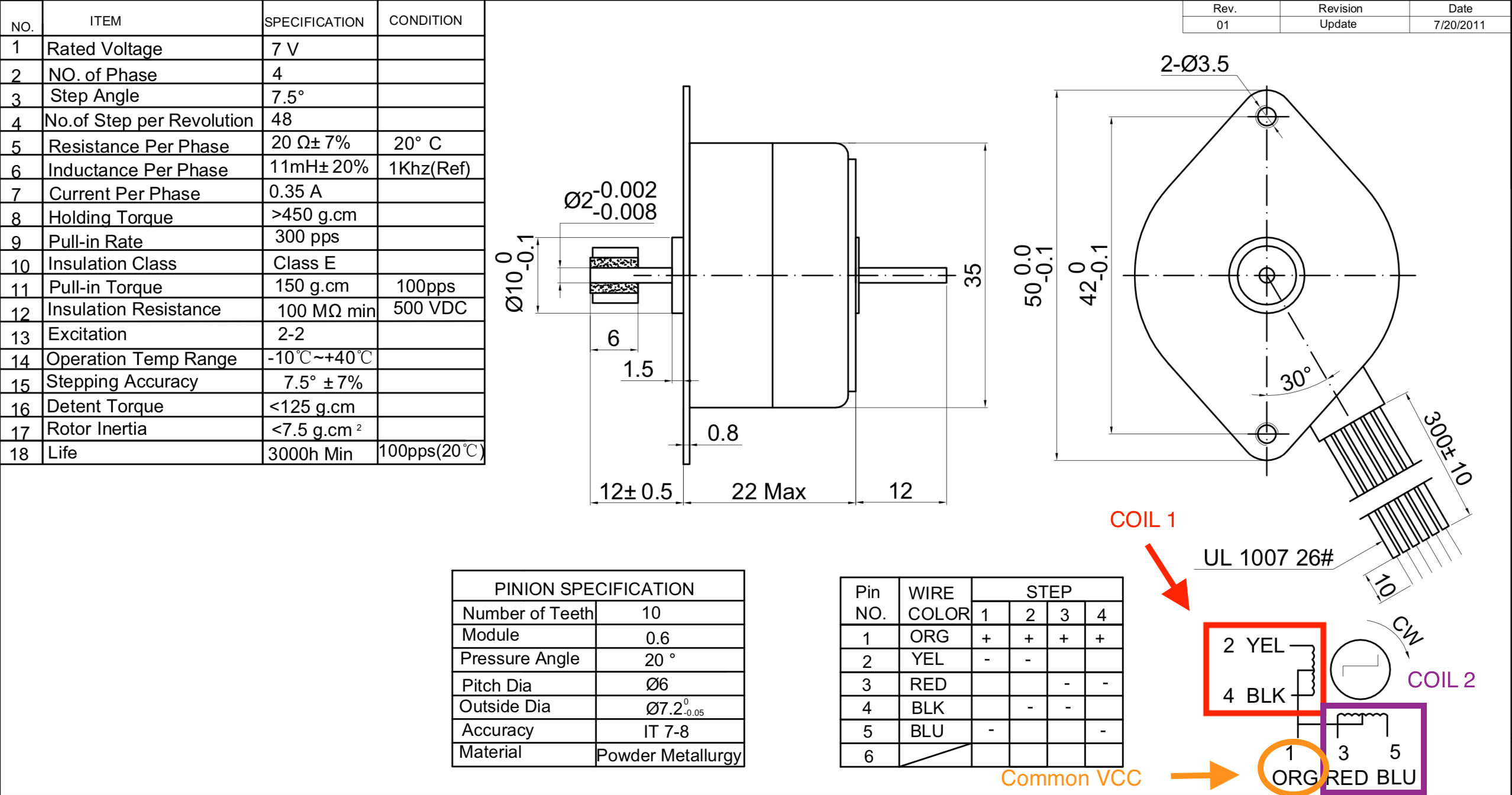
PCB Design - Unipolar 5 wires Stepper Motor
I decided I wanted to design a PCB for a stepper motor because it is probabily going to be useful for my final project. So I looked up professor Neil's PCB and started designing it on Eagle. This is the schematic I came out with:
And this the routing of the pcb:
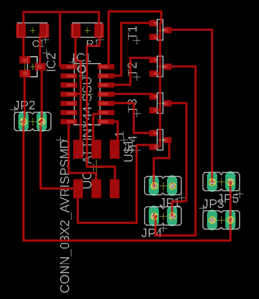
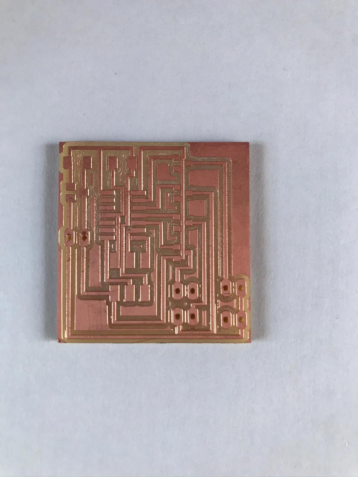
The result looked good so I edited the images on Gimp so I got a file for the traces, one for the outlines and one for the holes and then I put the pngs on mods and created g-codes. I milled the board with our Roland SRM-20 and this is the result:
I soldered all it's components and made all the connections using jumpers (this is the link to the datasheet):
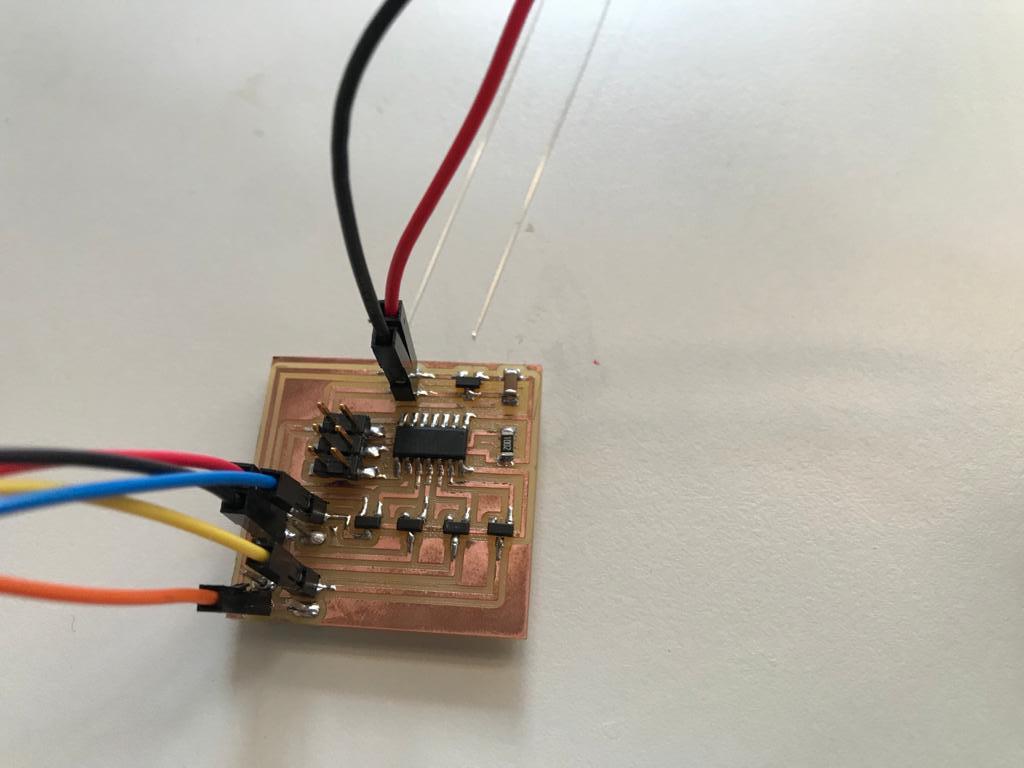
For the functioning of the motor I used the code below that I found with my instructor:
The motor worked fine as you can see in the video below:
video_stepper from Olivia De Masi on Vimeo.
Links
-http://wiki.seeedstudio.com/Grove-Buzzer/#getting-started
-https://www.lumex.com/spec/LCM-S01602DTR-M.pdf
-http://www.learningaboutelectronics.com/Articles/Servo-motor-circuit.php
- https://www.jameco.com/Jameco/Products/ProdDS/2138812.pdf