Week 9: Input Devices
Group Assignment:
1) Probe an input device's analog levels and digital signals.
Individual Assignments:
1)Measure something: add a sensor to a microcontroller board
that you have designed and read it.
GROUP ASSIGNMENT
Me and my collegues were not able to complete this week's group assignment due to Coronavirus.
INDIVIDUAL ASSIGNMENT
Useful research and learning links:
- How does a pull up resistor works?
- Book "Make: avr programming" chapter 6
- What is a voltage divider?
- Groove kit
- IDE Arduino's language
Because Italy is in total lockdown my instructor sent me a box filled with sensors, actuators, an arduino board and a groove kit so that I can test all of these components.
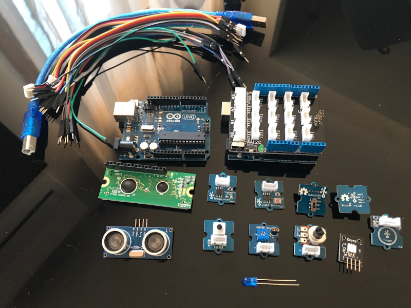
- Arduino Uno
- Grove system kit
- Button
- Slide button
- Light sensor
- Rotary angle sensor
- Ultrasonic sensor
- Buzzer
- LED socket
- Touch sensor
- Temperature sensor
- RBG color sensor
- Display
- Usb cable
- Jumpers
Button
I started testing the button on Arduino. I got the code from SeeedStudio which was this:
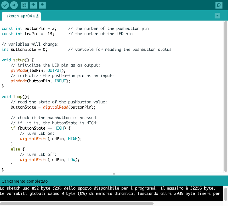
I gave the commands to compile and run the sketch and the button worked righ away turning on and off the LED on the board:
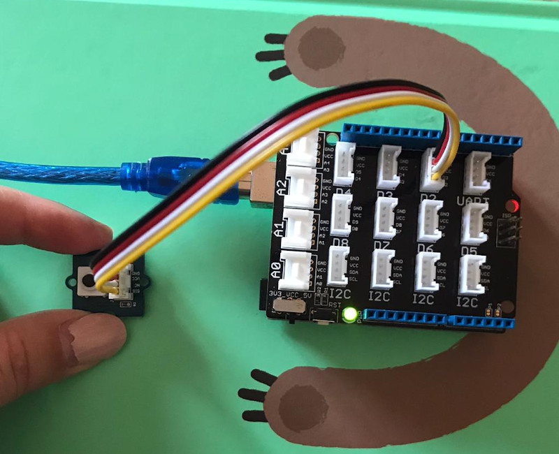
N.B. I attached the button to the D2 pins because that was what was written in the code (D is for digital). If I wanted to attach the button to another pin I should have changed the code.
Temperature sensor
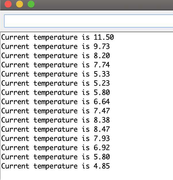
I then wanted to test an analog sensor so I tried out the temperature. As I did before I got the code from SeeedStudio which was this: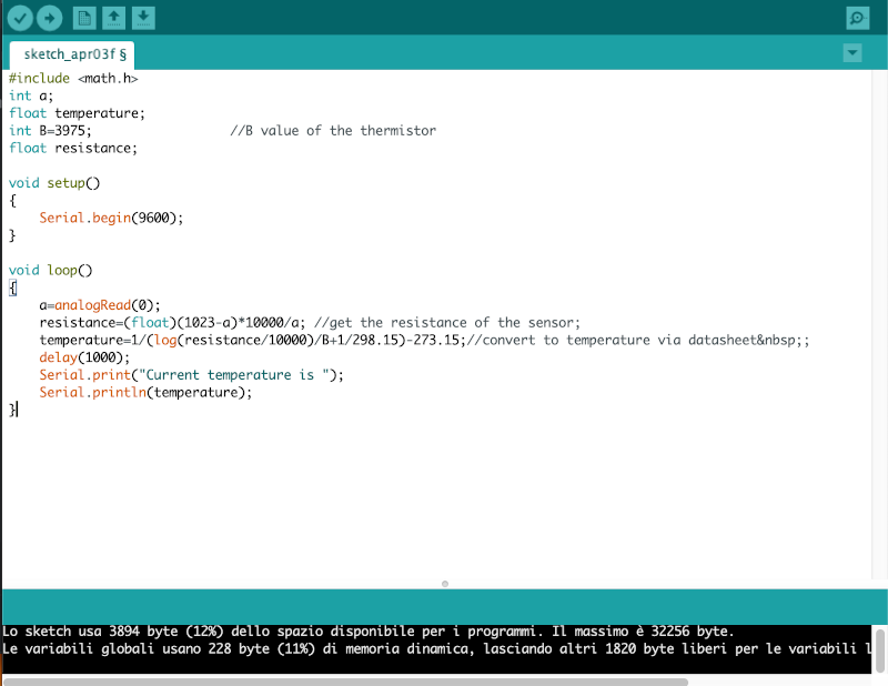
This was the feedback I got opening the serial monitor on IDE Arduino after compiling and running the sketch:
Ultrasonic sensor
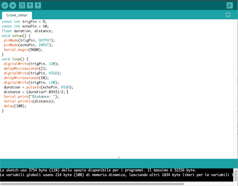
After the button and the temperature sensor I tried a cooler sensor: the ultrasonic sensor! This is the code I used on Arduino:
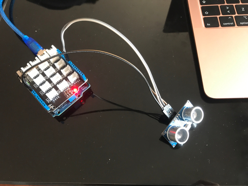
And this is how I connected the sensor to the board using jumpers. I had to be carefull and connect GND to GND, VCC to V5. Then I had two other pins on
the sensor: TRIG (output) and ECHO (input). I downloaded the board's datasheet and I cheched which pins were which and I was then
able to make the right connections.
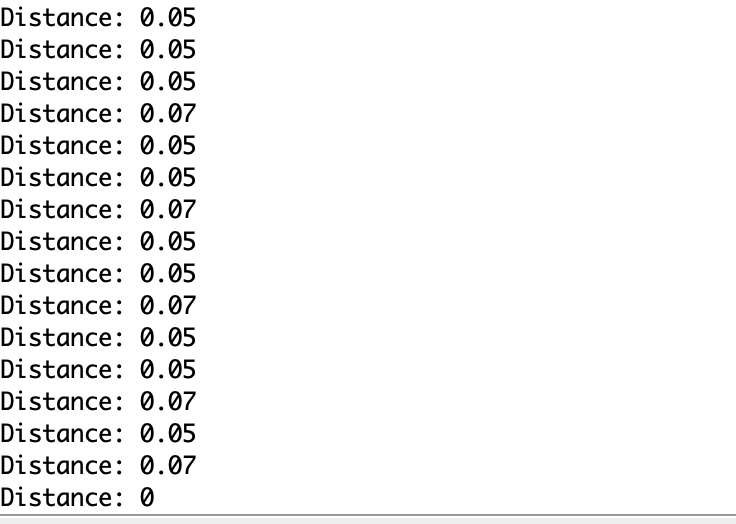
This was the output on the serial monitor:
And in this video I show you how it actually works live:
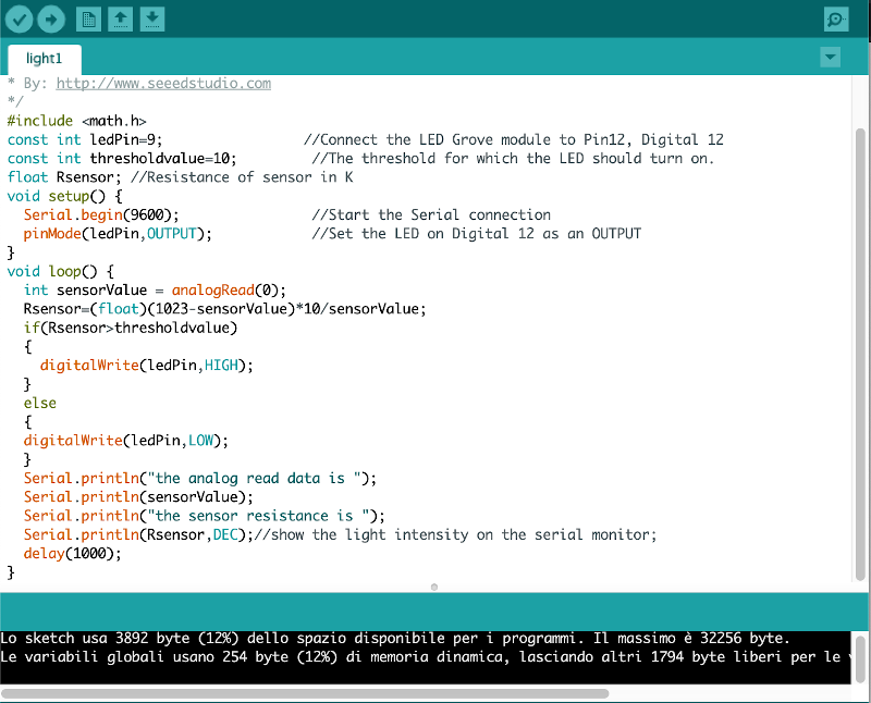
Light sensor
This is the light sensor testing I had in my box. As usual, I got the code from SeeedStudio and I created with it a new sketch on IDE Arduino:
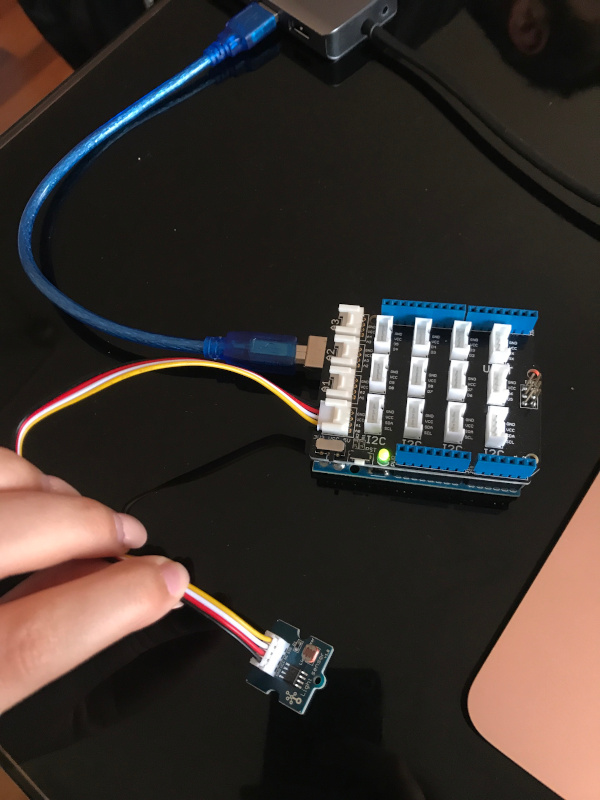
This is the connection I made based on the code:
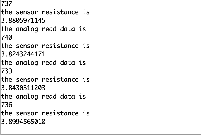
And this is the output on the serial monitor:
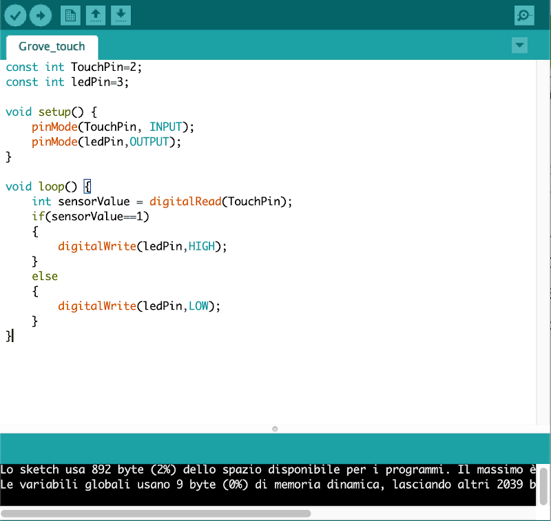
Touch sensor
Another super cool sensor to test was the touch sensor. To work out the functioning I looked up the instructions on SeeedStudio because I found out I had to use two components: the touch sensor
and the LED socket with and blu LED through hole. This is the code:
With the help of a multimeter (that my collegue Elena had, thank you!) I found out that the long bar of the through hole LED is positive so I inserted where the + was written on the LED socket. And this is the result:
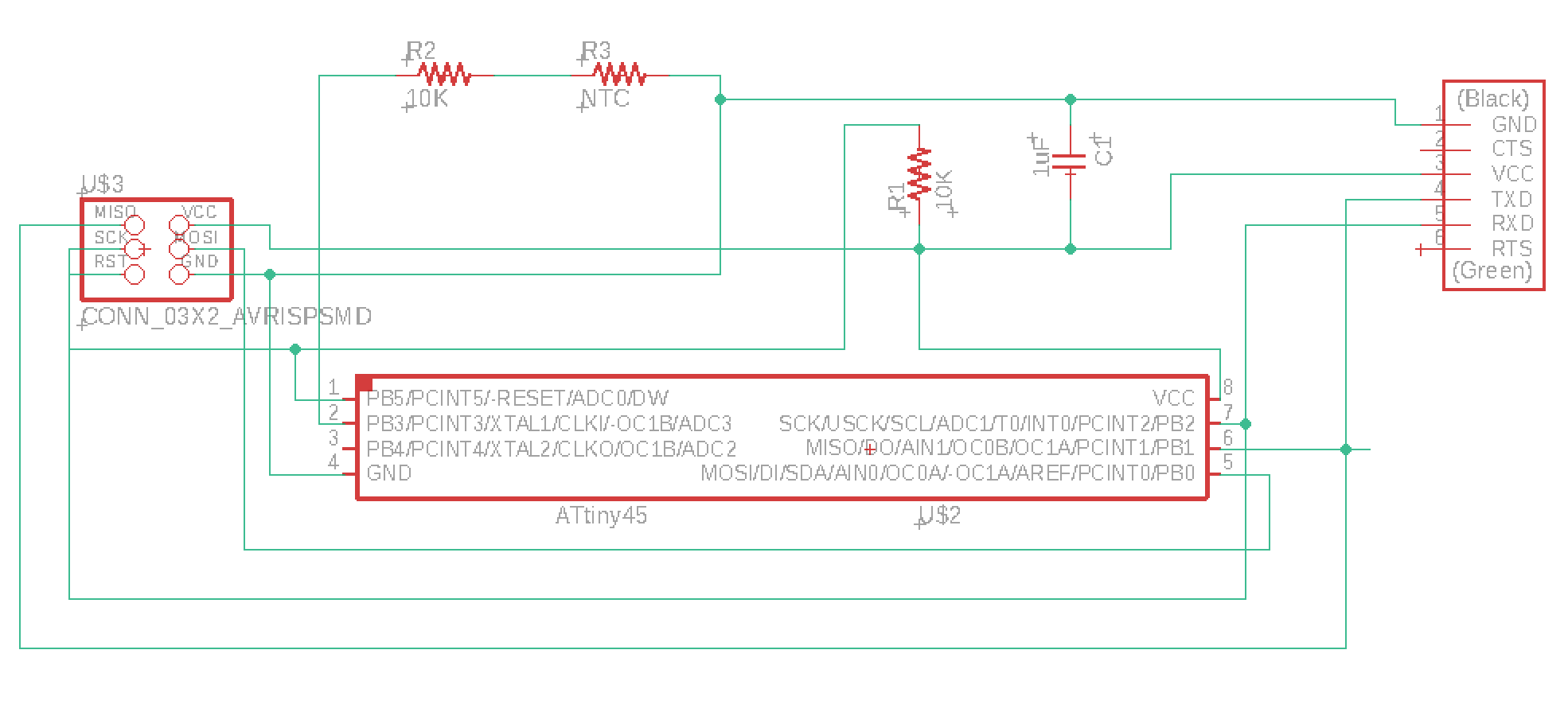
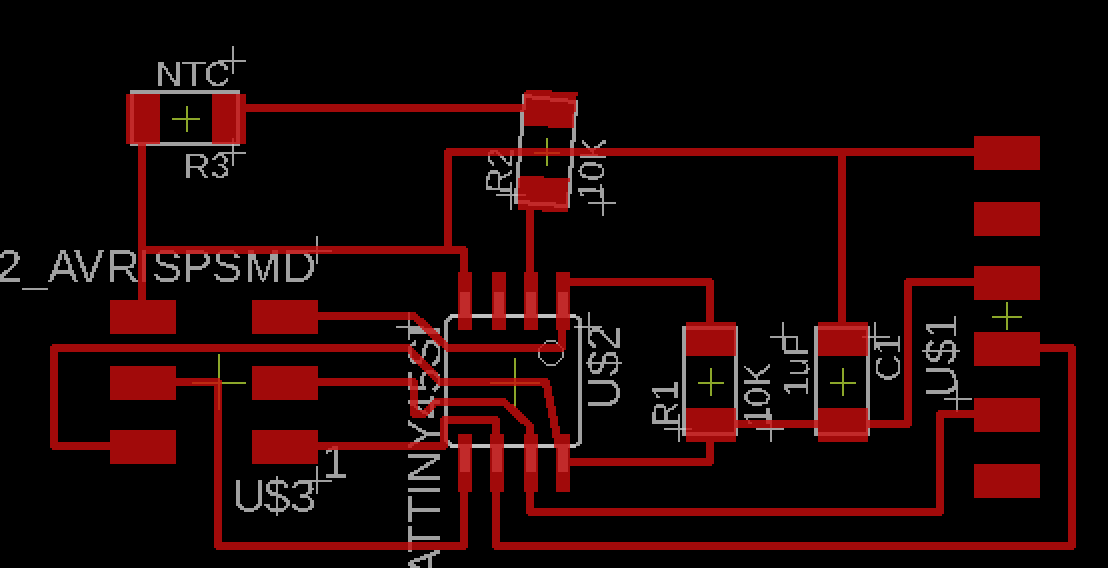
Board Design
I used Eagle to design an Attiny45 board adding a thermistor and this are the schematic and the board:
Links
- https://learn.sparkfun.com/tutorials/pull-up-resistors/all- https://learn.sparkfun.com/tutorials/voltage-dividers/all
- http://wiki.seeedstudio.com/Grove_System/
- https://www.arduino.cc/reference/en/
Improvements
Downloads
Attiny45:
- Thermoresistor Eagle files
- board
- components
- traces
- outlines