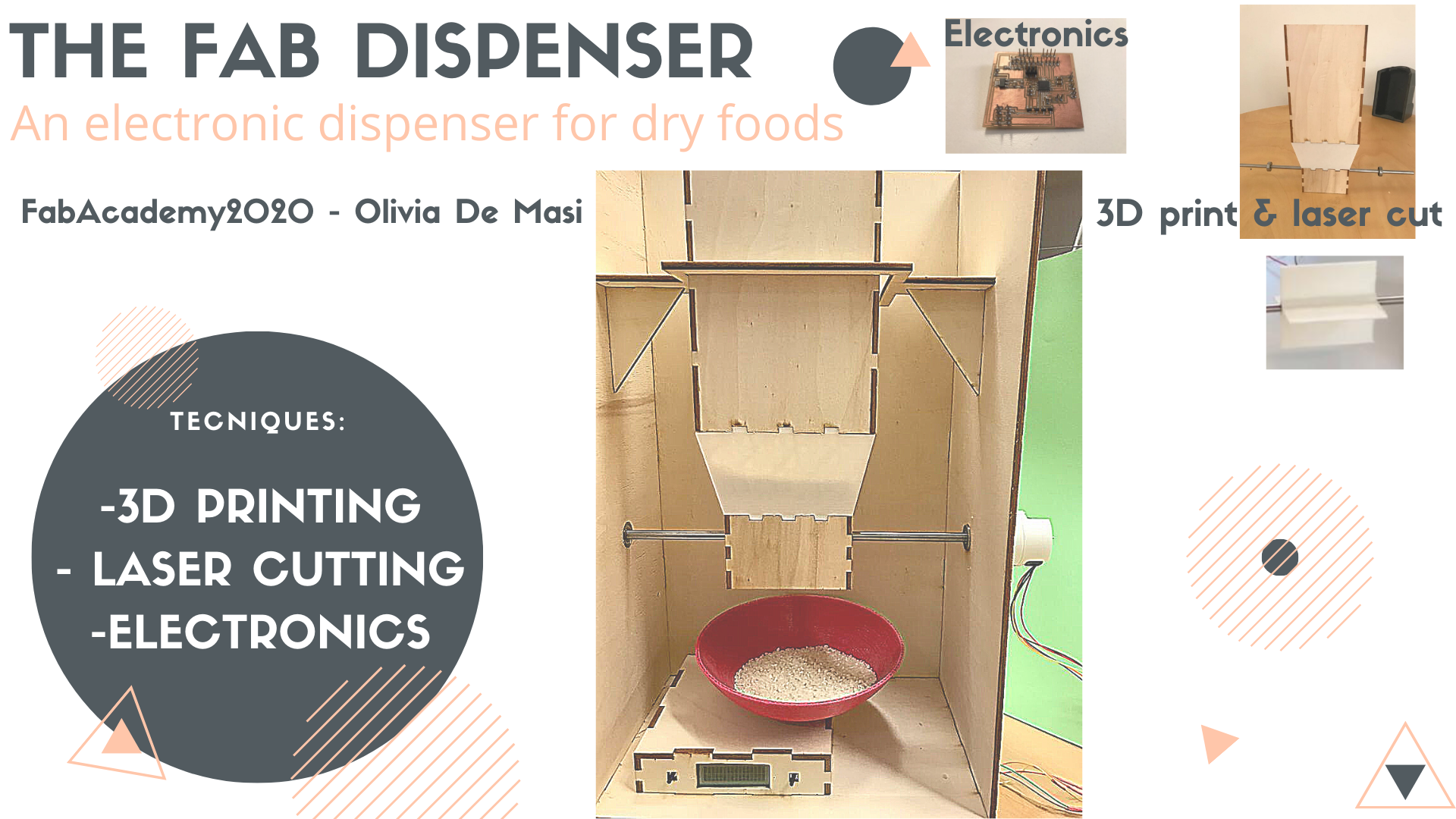
Concept: the idea of this project about smart packaging and creating a circular system of reusable capsules and distributors for dry foods.
Cad modelling and assembling: I'll have to 3D model the distributors and the reusable cups and find the right material to print/mold/cut them.
Electronics: I'm going to mill and program boards for the tracking of the cups and for the mechanical part of the distributors (opening and closing when the cup is underneath it).
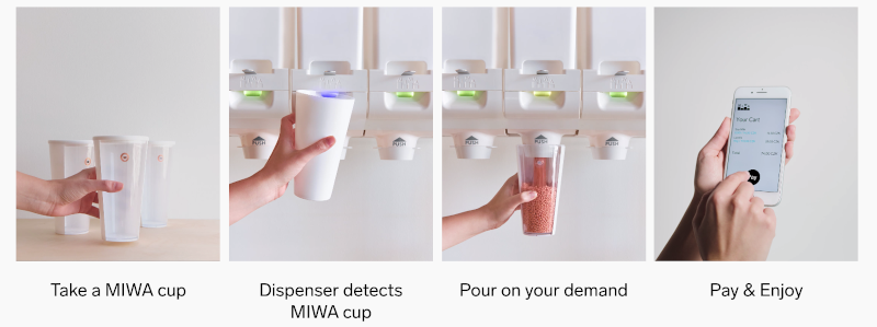
Benchmark: The inspiration for this project came from a brilliant Chech company called MIWA (MInimum WAste):
http://www.miwa.eu/
3D MODELLING
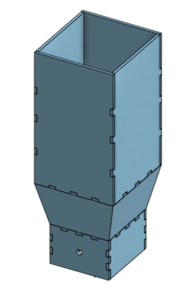
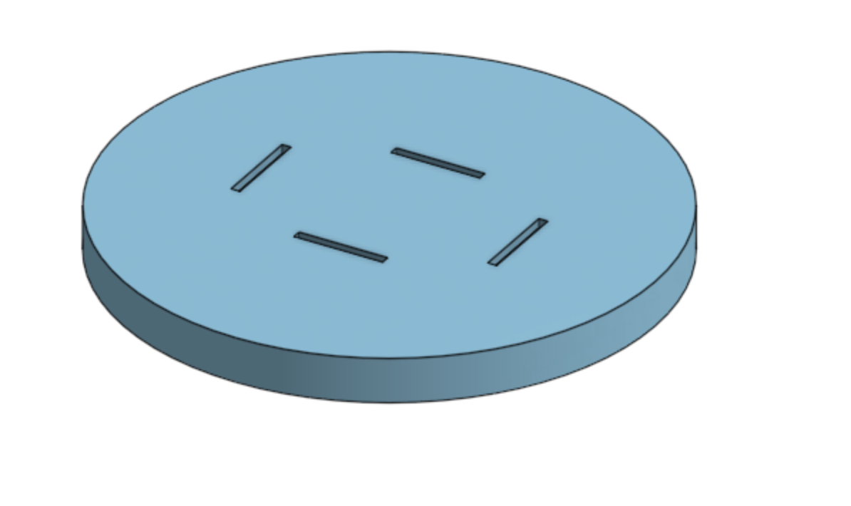
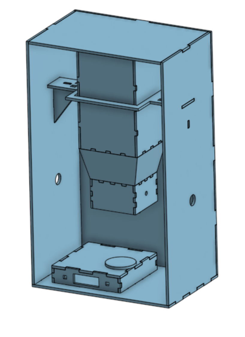
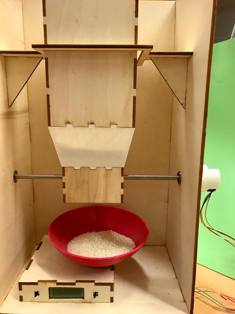
I started modelling the dispenser of food as I new I had to have an idea of the dimesion I wanted to give the whole cabinet, so the project it self. I had to figure
out how to create the funnel to narrow the dispenser. I decided that the best way was to laser cut wood for the top and the bottom parts and to 3D print the funnel.
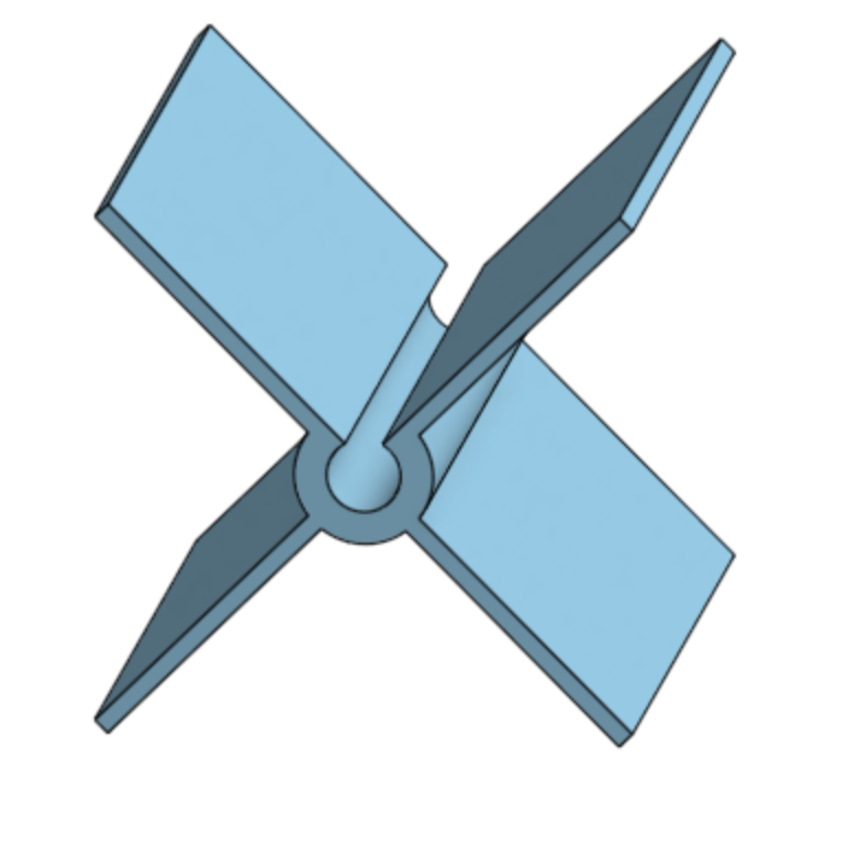
I then designed the helix that was going to make the food fall down, and I decide to leave the middle hole (in which the iron bar connected to the stepper motor had to be) open to gain more flexibility.
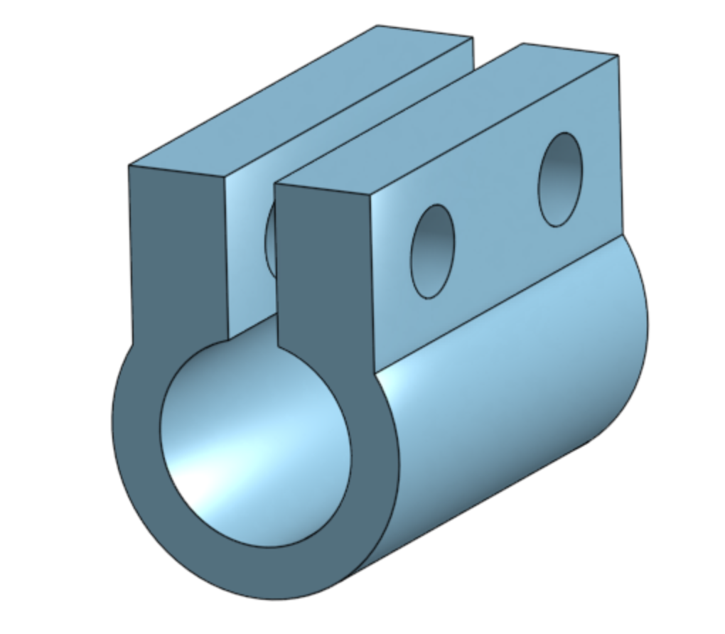
I then designed a gasket to link the stepper motor to the iron bar and the helix. As I did for the helix I left the hole in the middle open and I added two holes for two screws to tighten
the gasket around the motor and the bar.
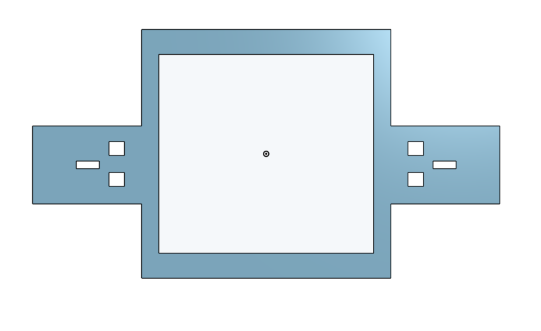
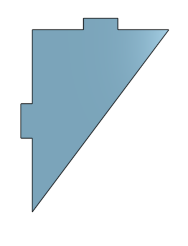
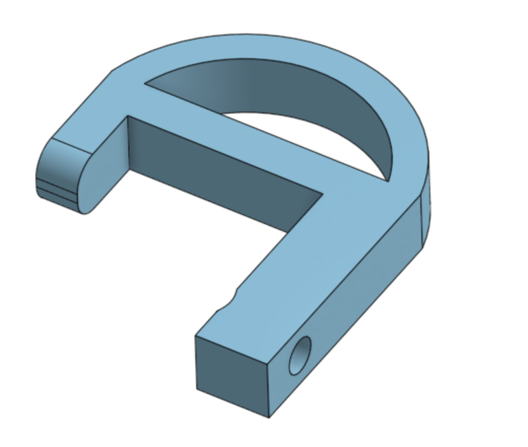
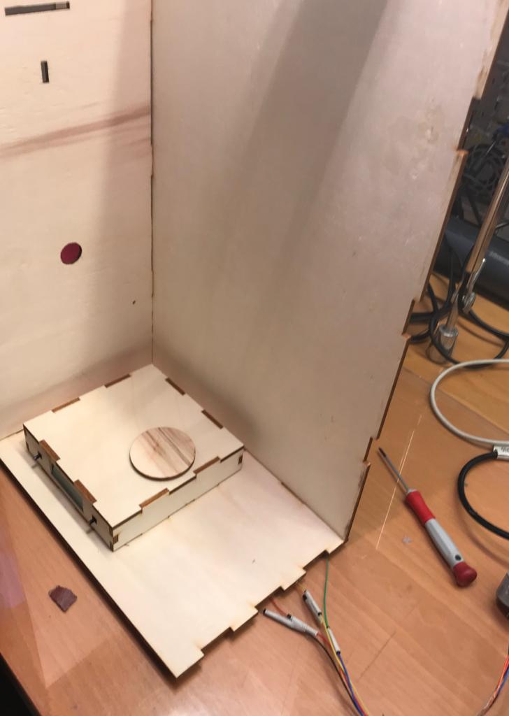
I designed the external cabinet as a rectangular box, but I had to figure out how to make the dispenser hang from it. So this is the support I designed, and next to it are the wooden brackets that I used to
hold it firmly to the carbinet's side:
And the of course I put 4 3D printed hooks that uses gravity to make the hole thing more solid:
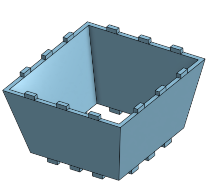
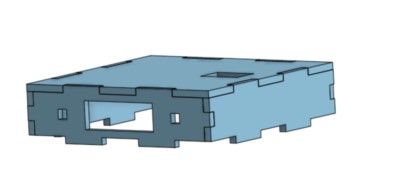
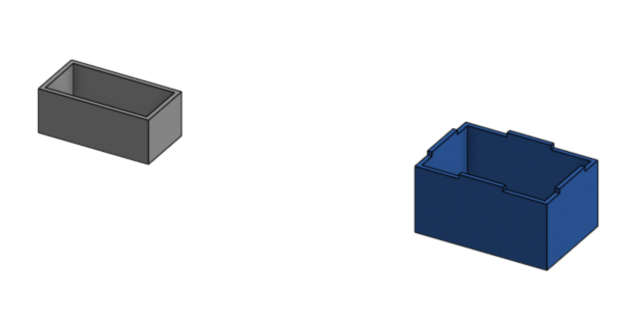
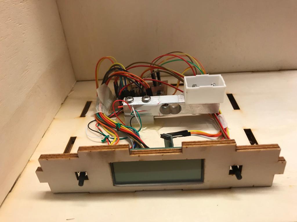
I then made a smaller box which was made to contain the loading cell, the LCD and the buttons.
ELECTRONICS
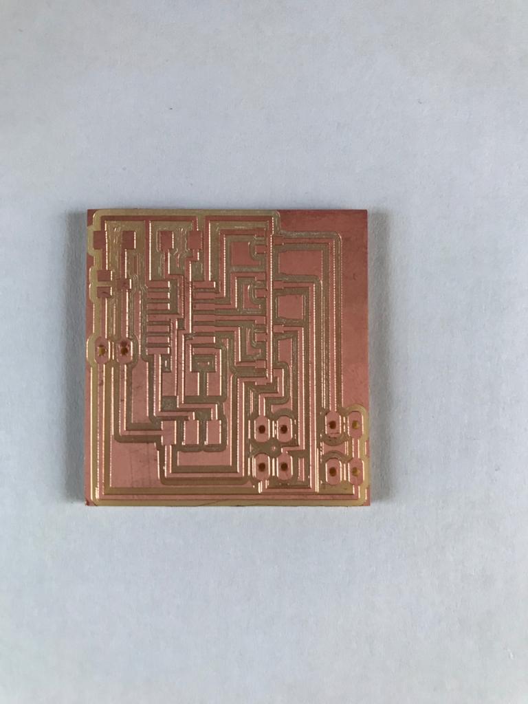
For the elctronic part I started from the stepper motor as I didn't use it before. I made a PCB looking at the fab schedule.
I then wrote a code to make the stepper start and it worked:
IMG_3355 from Olivia De Masi on Vimeo.
Then I thought about what the pcb had to do drawing some diagrams and I resulted with the following components:
- 1 stepper motor
- 2 buttons
- 1 LCD display
- 1 load cell
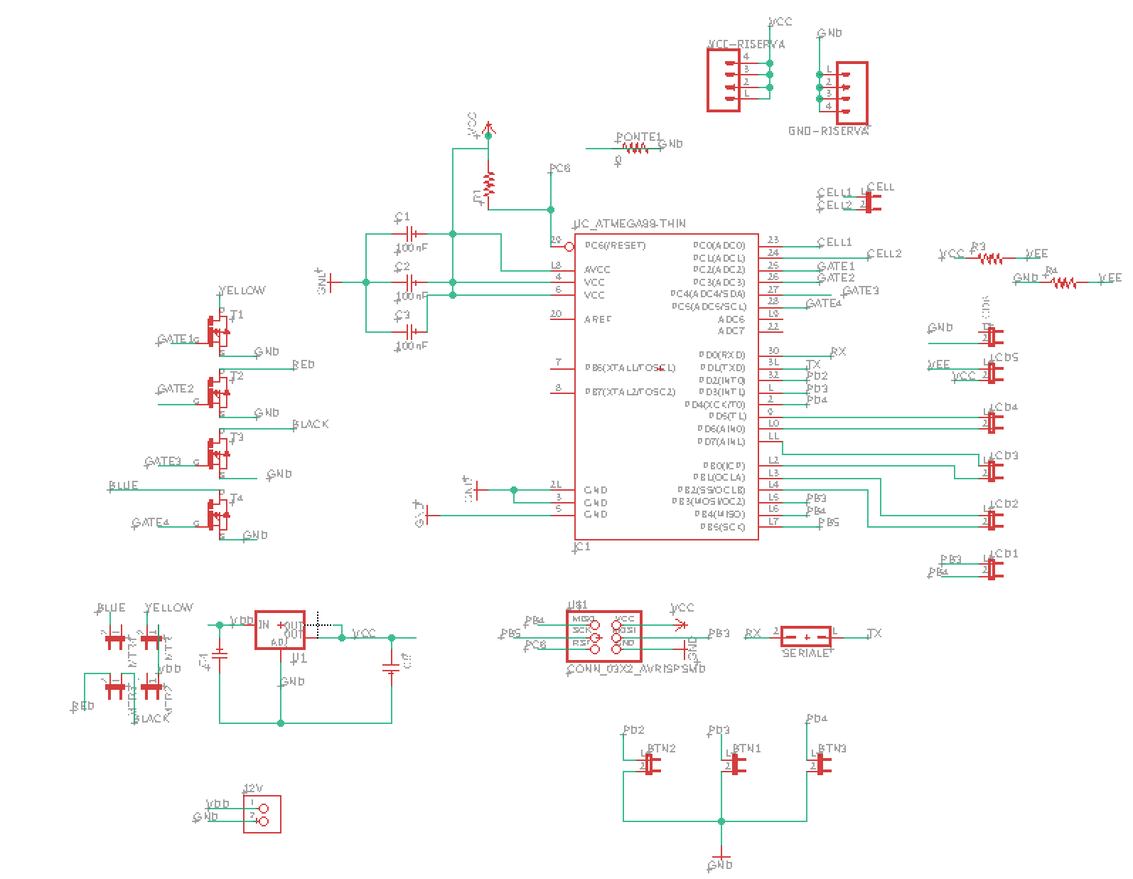
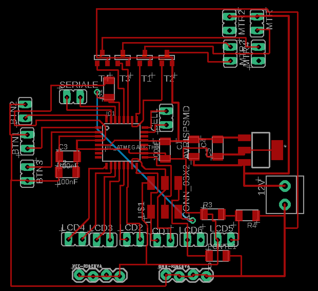
I started the design of my pcb using Eagle. This is the schematic and the board:
Here you can download the files: schematic, board.
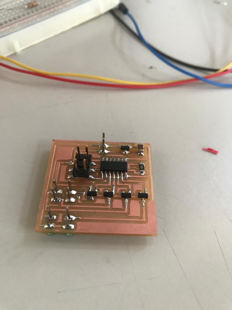
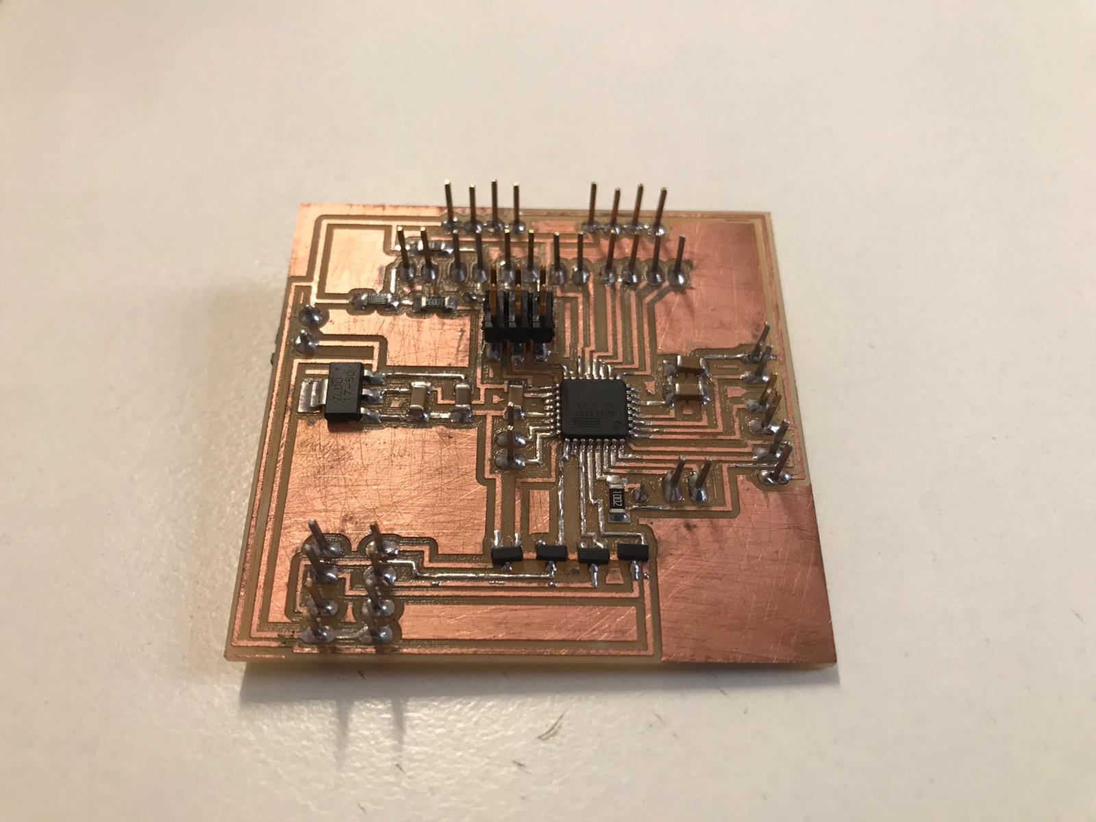
And here is the soldered board (looks great!):
As a first thing I tested the stepper motor to see if it's traction was enough to turn the helix.
FIRST TEST
elica from Olivia De Masi on Vimeo.
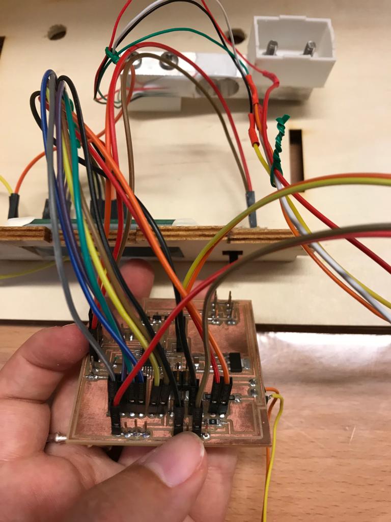
I carefully connected all the wires of my components to the pcb after testing each one individually.
And the one below is the code for the final project:
Embedding and Assembling
Electronics components:
Cabinet components:
video_ok from Olivia De Masi on Vimeo.