Group Assignment:
1) Characterize your lasercutter's focus, power, speed, rate,
kerf, and joint clearance.
Individual Assignments:
1) Cut something on the vinylcutter.
2) Design, lasercut, and document a parametric construction kit,
accounting for the lasercutter kerf,
which can be assembled in multiple ways,
and for extra credit include elements that aren't flat.
You can find our group assignment for this week clicking this link.
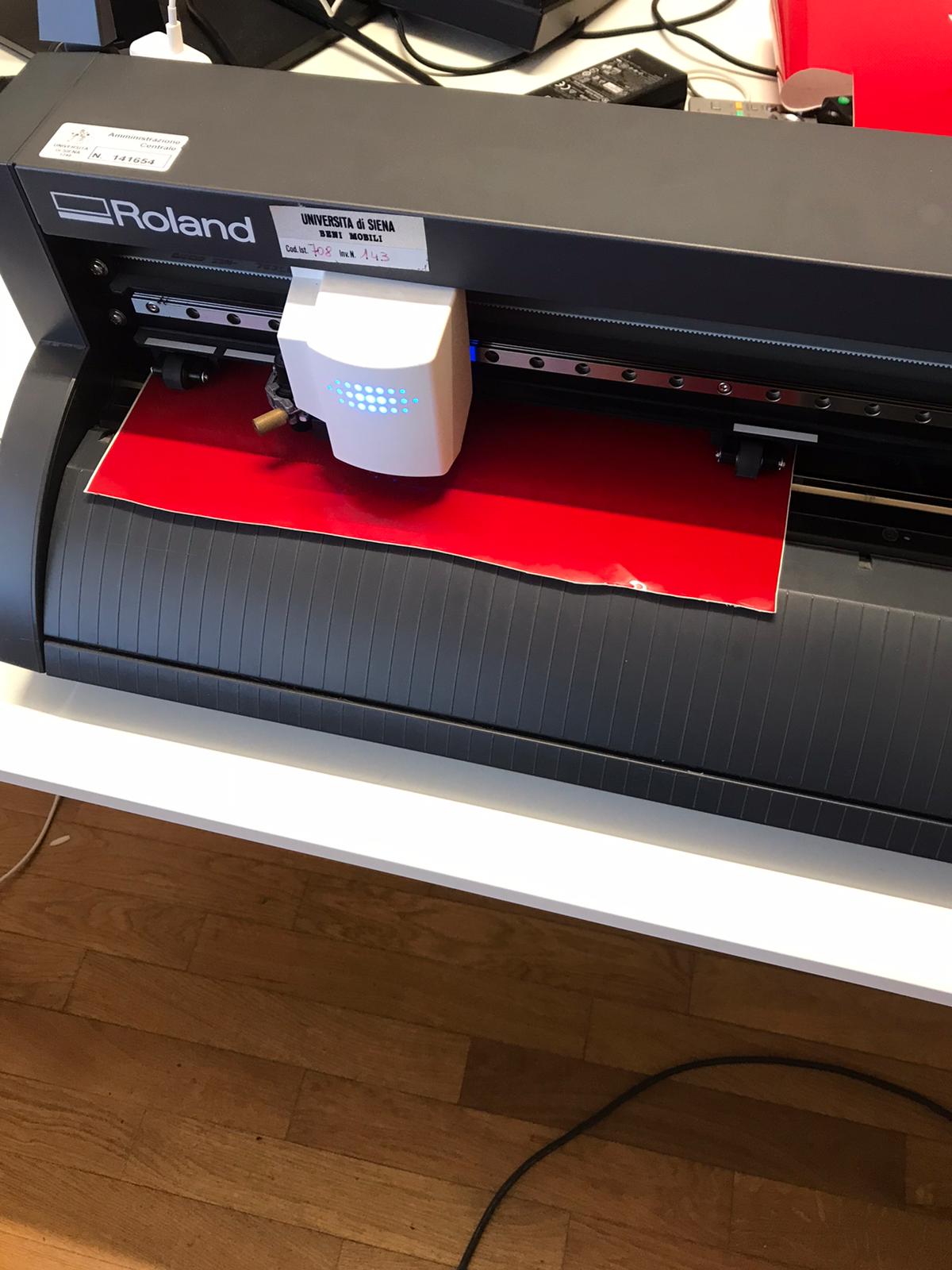
I've started this week dealing with the first assignment: cutting something with vinyl cutter! So, as a first thing, my instructor showed me the vinyl cutter "Roland" and it's functions.
The main thing to eknowledge is that to vinyl cut some shape or image it has to be a vector one. So I relied once more on Inkscape and I imported a raster image.
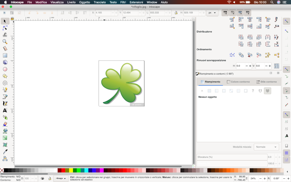
Unfortunatelly I soon realised that my image was not so "fitting" for this project as it had a few shadows in it. I replaced it with a more accordant. I imported into Inkscape and gave the command "trace bitmap":
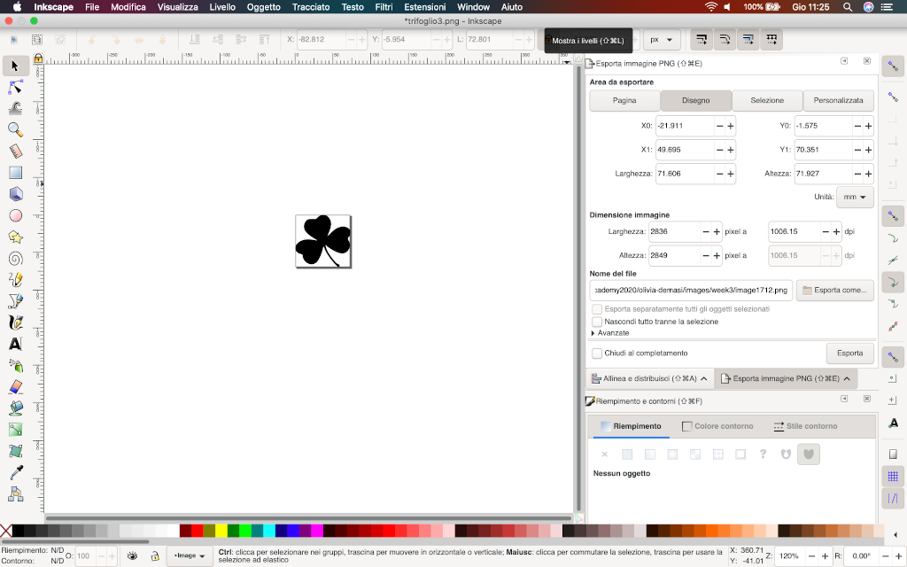
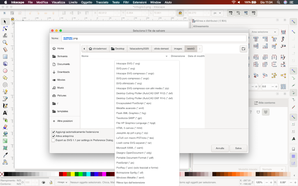
Now that the image I want to vinyl cut is a vector I want to import it on CutStudio. Here is where i found troubles: my Inkscape file won't let me save it as a png. This are the formats the software told me I could choose:
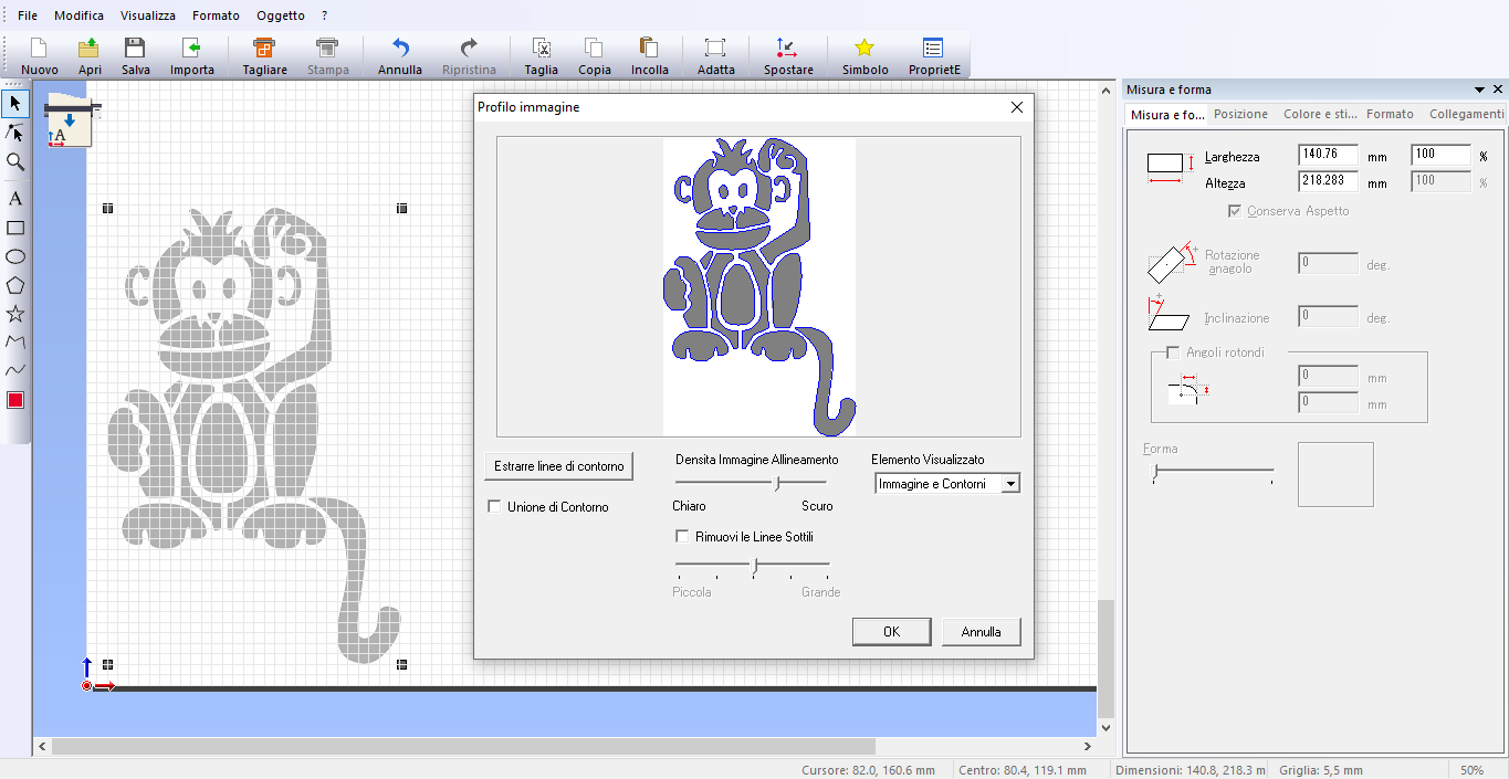
So, actually, what I had to do was save my svg file on a pen drive and put it into my instructor's computer. I could then save it as a png file and import it on CutStudio. I did a few shapes to try the sofware's and the machine. On CutStudio I can now see my image but I still have a couple of commands to give: right click on the image and a menu comes up where I click on "Image profile". On this other menu I can see the preview of my image and I must press "extract contour lines".
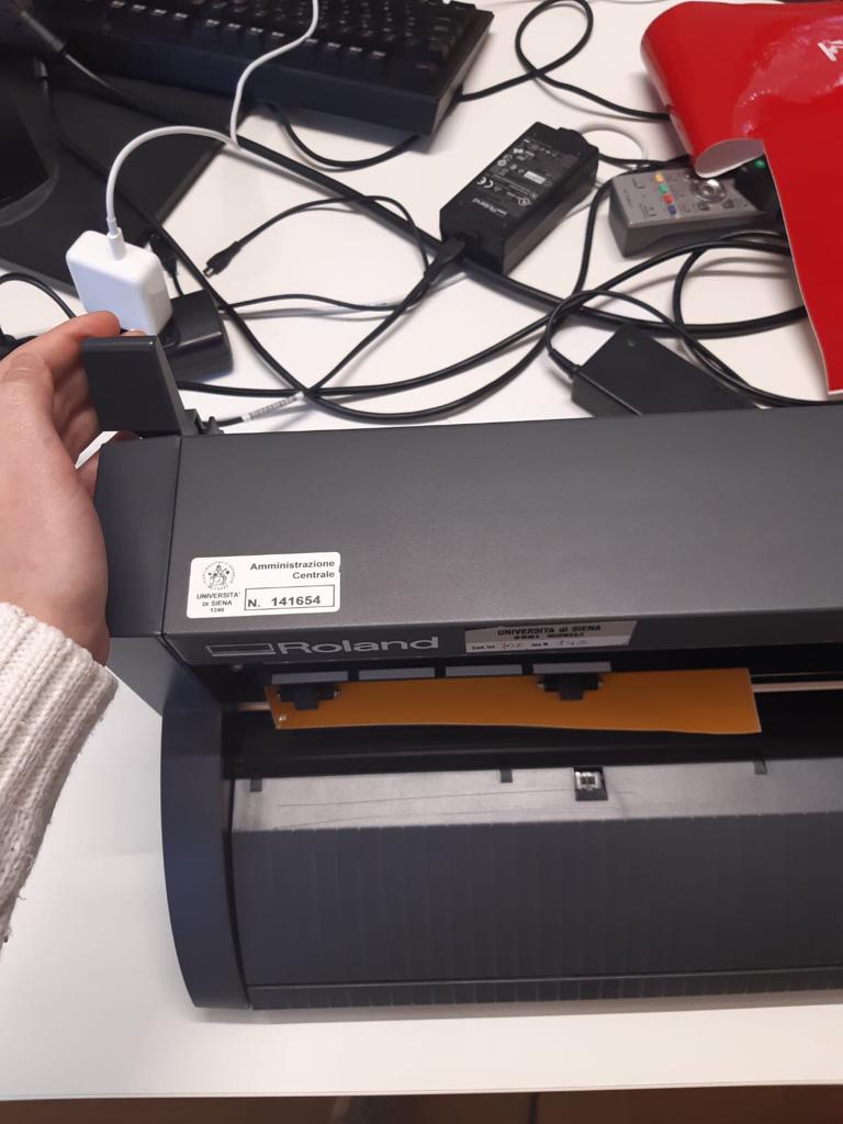
In the mean time I have to set my vinyl sheet in the machine by pulling down the lever and inserting the sheet. This is the lever:
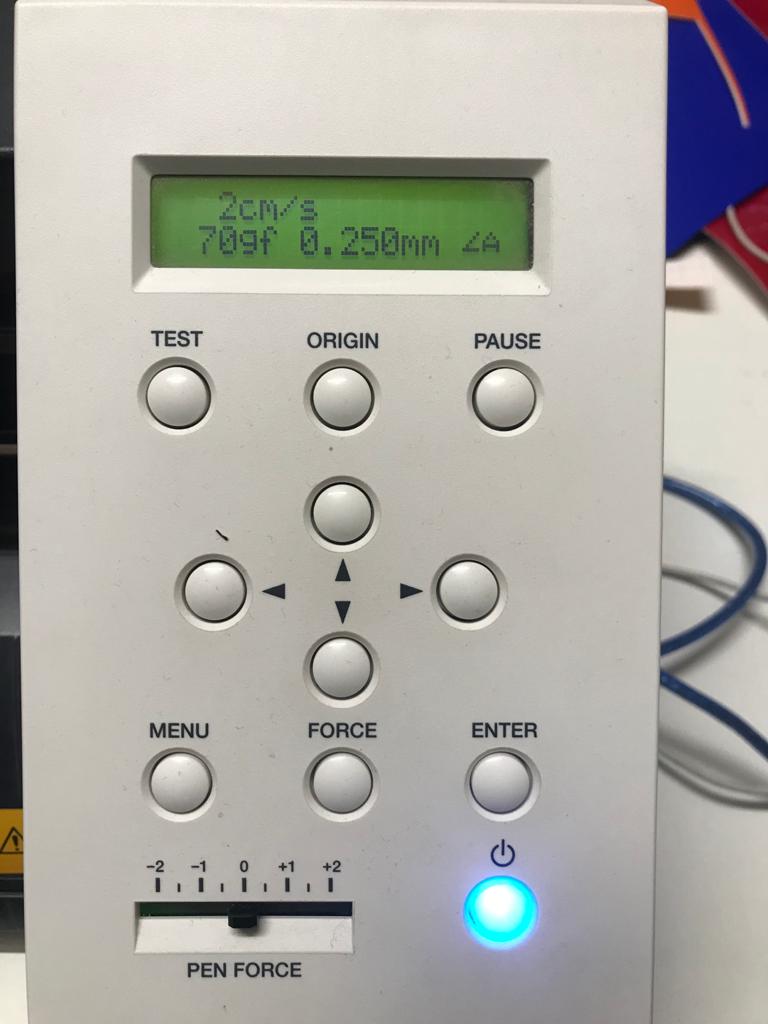
And this is the command board:
Now I have two overlayed images of the monkey so I have to drag one near the other. I can delete the one on the lower level and keep the one that i moved. Now that my image is set and ready I can clic on the tool bar "Cut", checking that everything is as I want it and press "print".
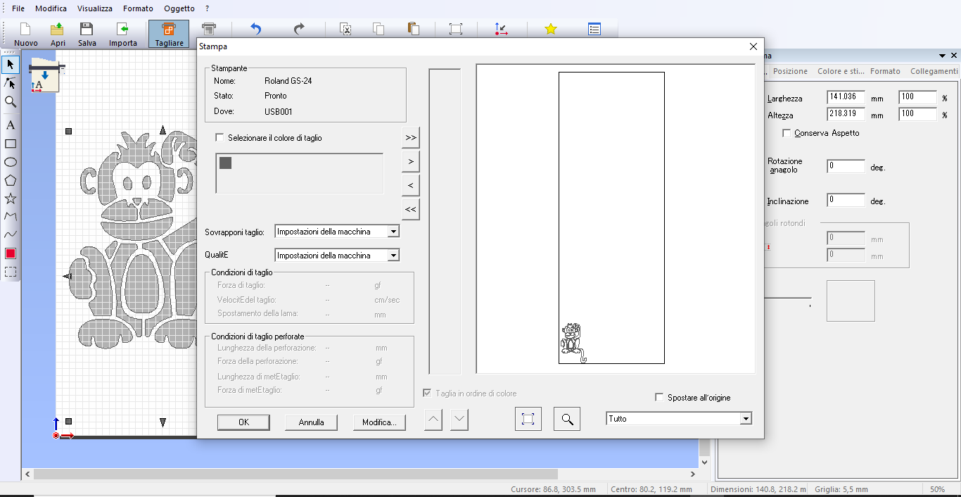
The machine will start to cut my sheet:
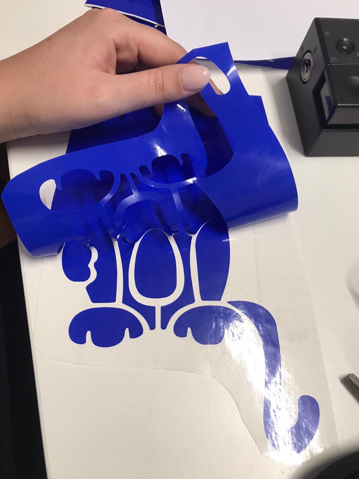
At the end this is what I got:
I started this fase thinking of a certain parametric construction kit, which it was supposed to be a picture frame and a fruit bowl so I started drawing it on paper and the on Onshape.This was my frame:
These we're my holders:
I was drawing a second frame formed by two small ones when I realised my kit was getting overneed complicated so I decided to start a fresh one. Anyway, if you're curios, this was a part of my assembly:
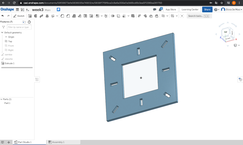
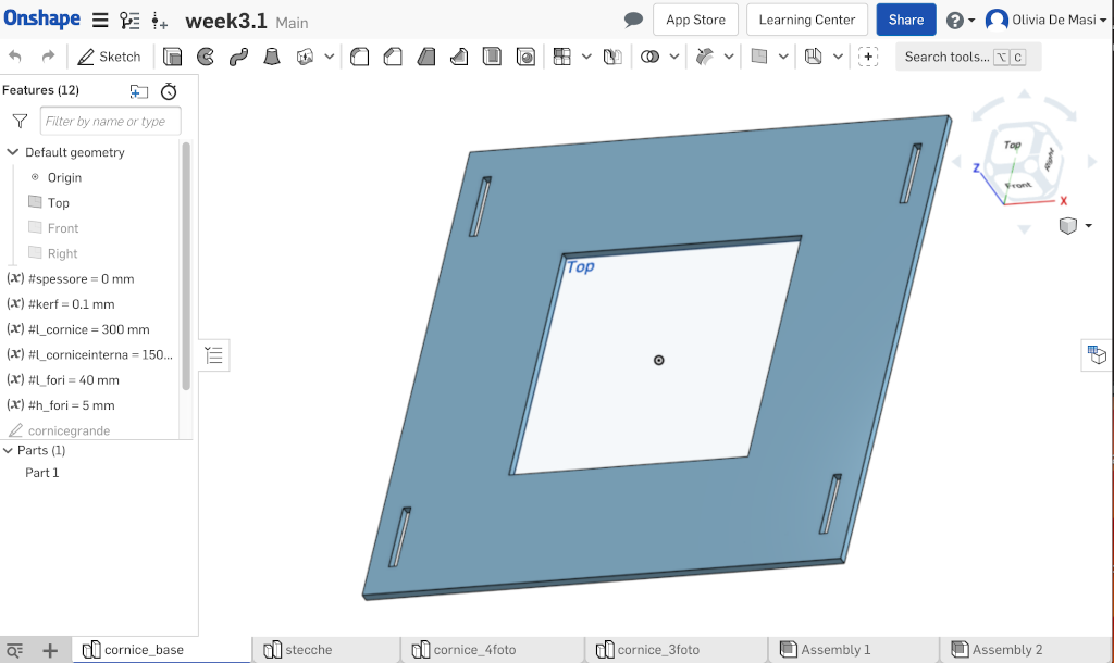
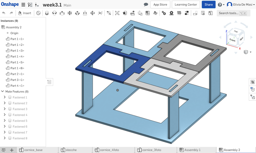
As a construction kit I decided to do some assemblable picture frames. I used Onshape to draw the first frame with four holes for the joints of 4 holders:
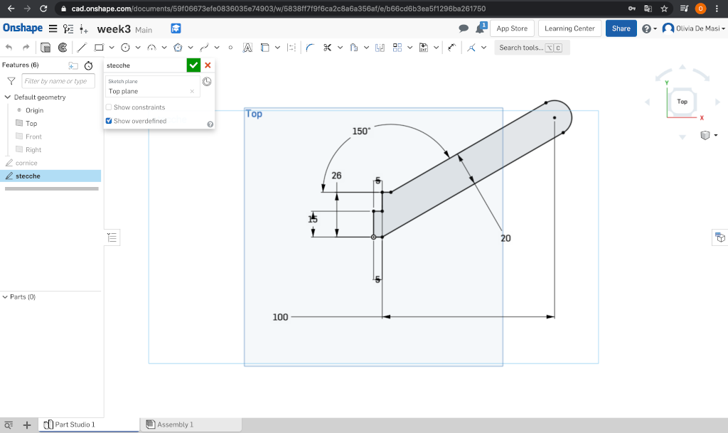
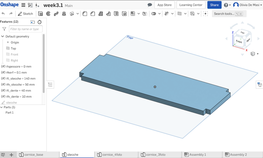
Then I drew the holders in another sketch:
In the third sketch I drew 4 smaller frames to join the holders:
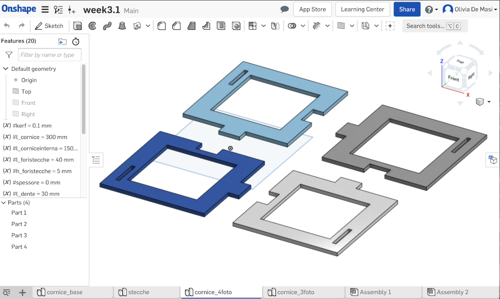
In the last sketch I drew 3 other frames:
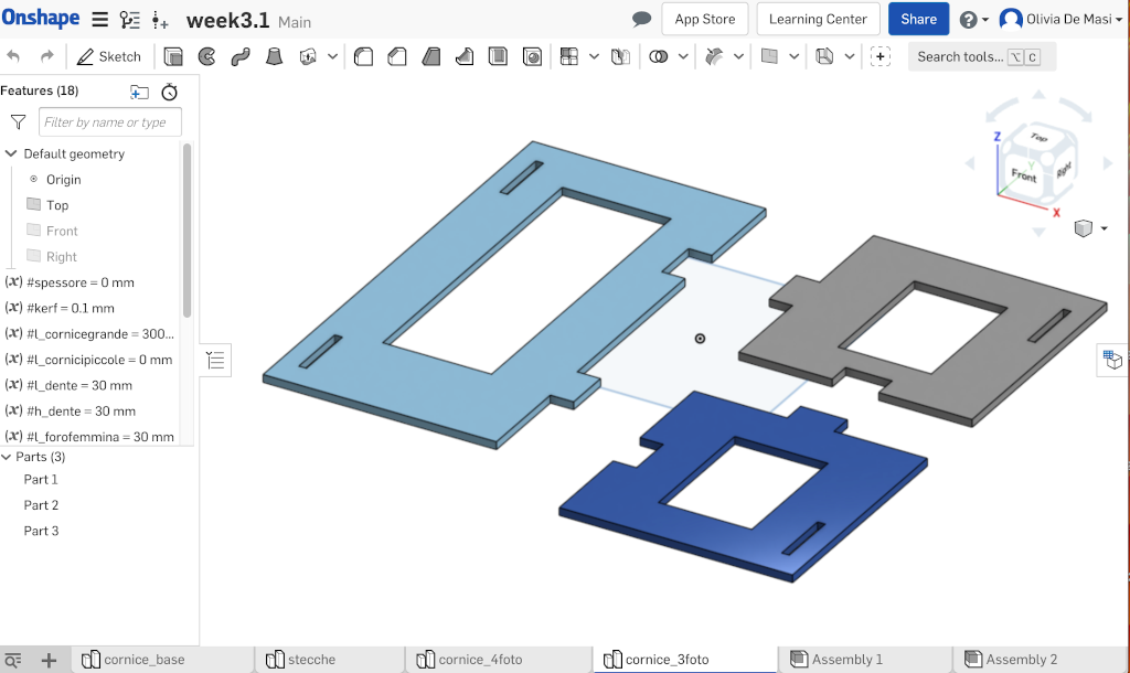
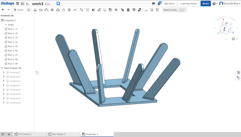
I used all the parameters as you can see in the pictures, as well as the kerf, which me and my class calculated during the group assignment (Santa Chiara Fab Lab - Week 3). In the assenbly part everything fits:
So, I went to cut all the pieces with the laser cutter using plywood:
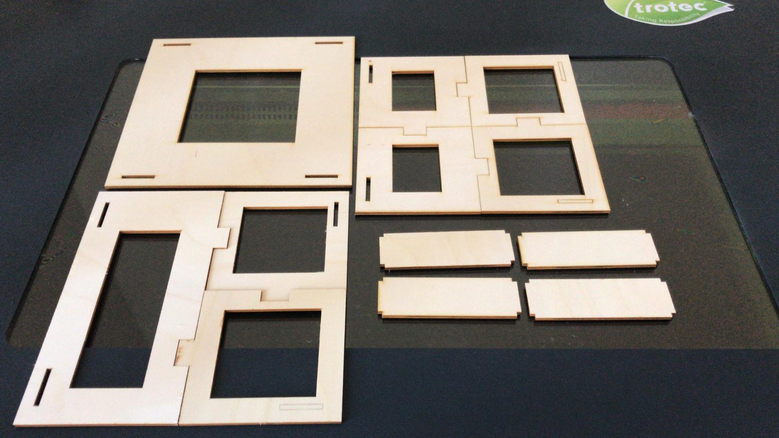
Unfortunatelly I did the very silly mistake to NOT insert the wright kerf variable and my pieces didn't fit at all. I will set the kerf again and cut it properly in the next few days.
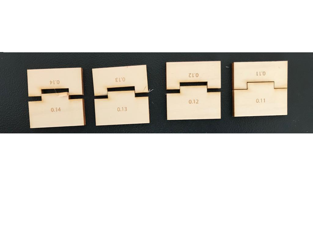
I went back to recut my parametric construction kit confident with the settings me and my collegues found in february, but, just to be sure, I only cut two pieces. Fortunately I did this because the pieces didn't fit one another. I checked the design as a first thing but everything seemd fine. So I checked the settings and they were the same we used in week 3 for the kerf tests and they worked fine. So the last thing to do was to calculate the kerf again. I put 0.1 mm the first time so I tried 0.15 mm the second time. It fitted but it was a little bit hard, so I decided to test the kerf all over again. I designed 8 small puzzle pieces adding kerf from 0.14 to 0.11 mm so that I was going to be sure about the result. I always kept the same cutting setting: 85 power and 1 speed. These are the cutted pieces:
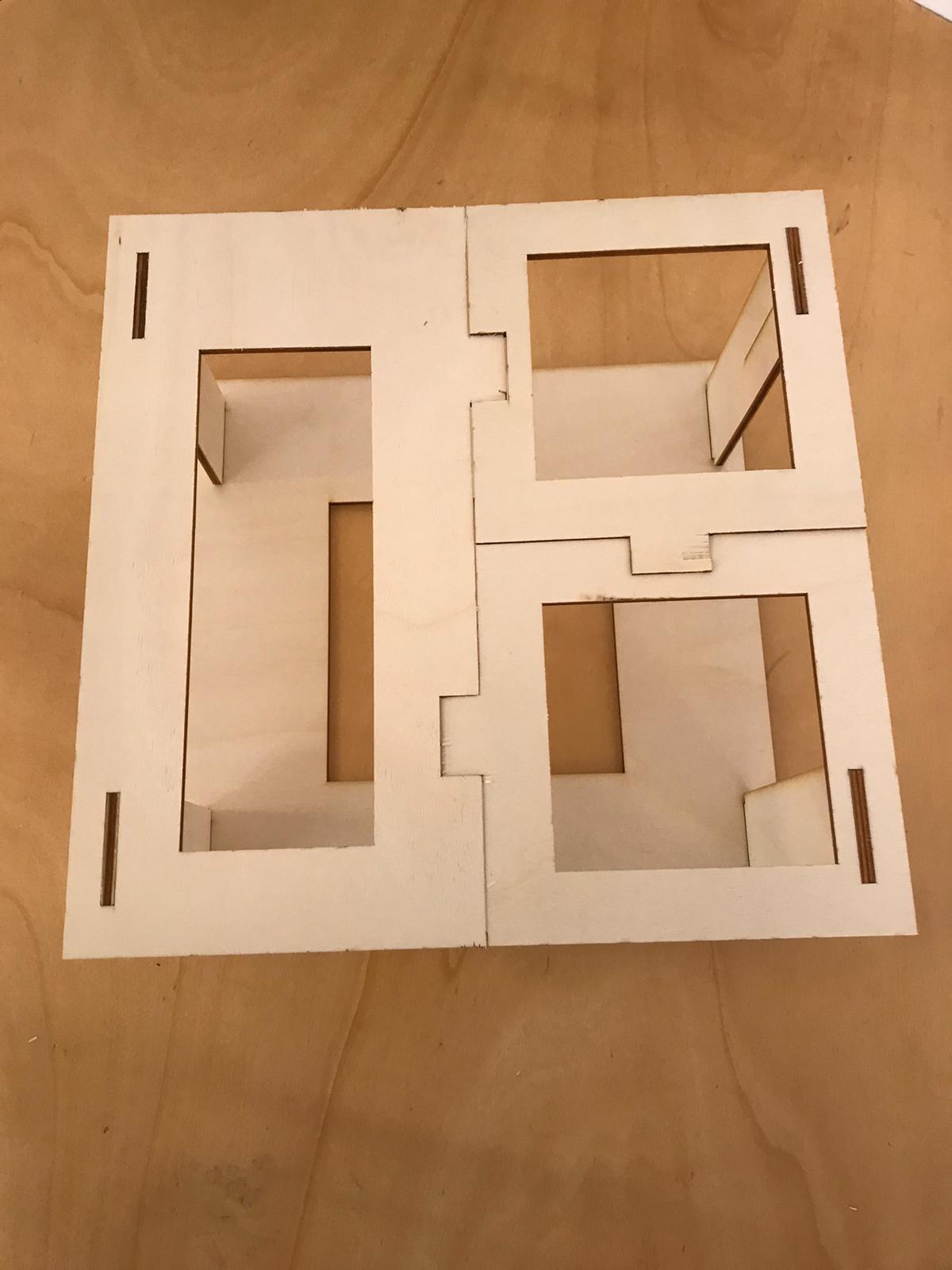
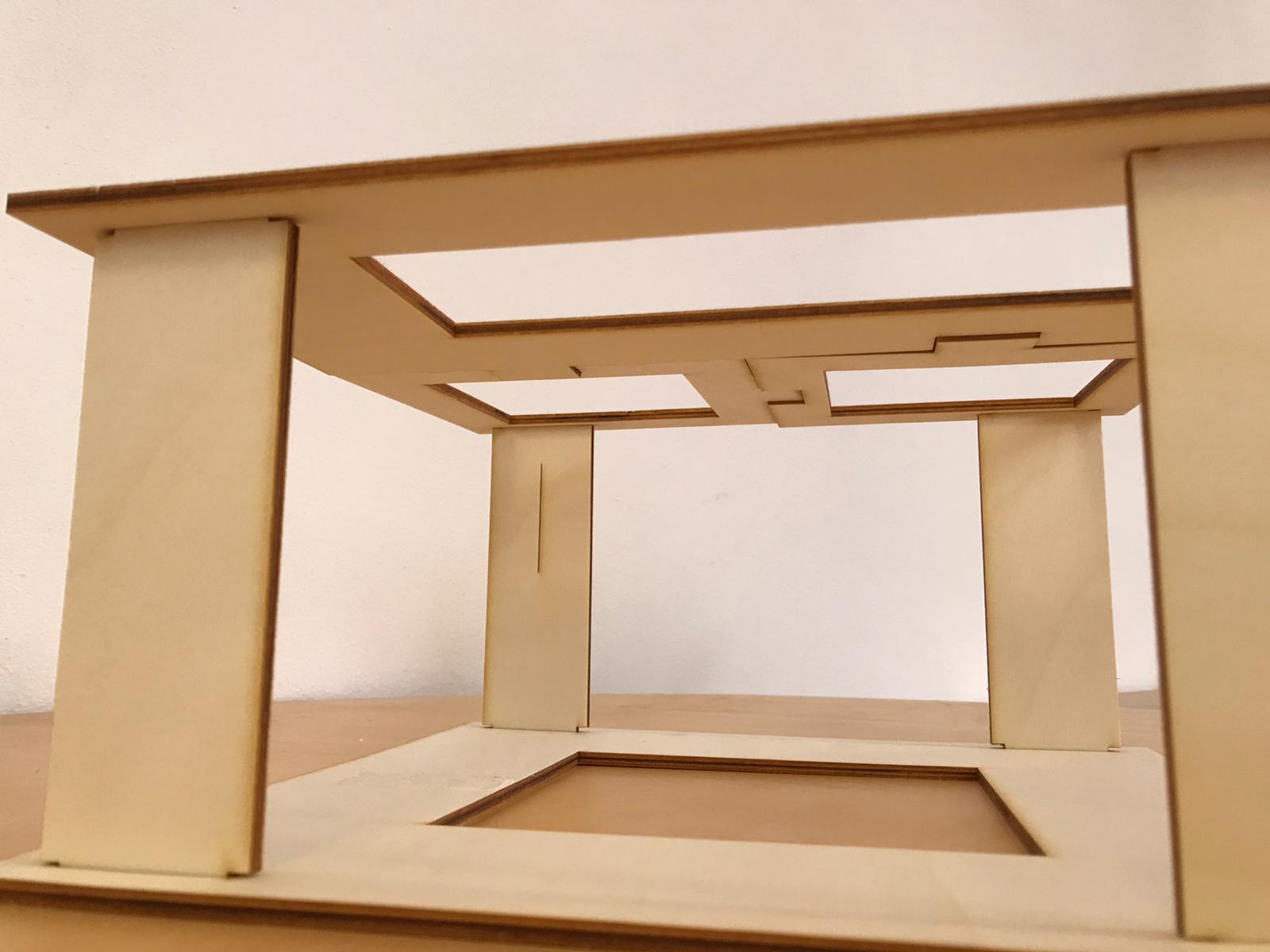
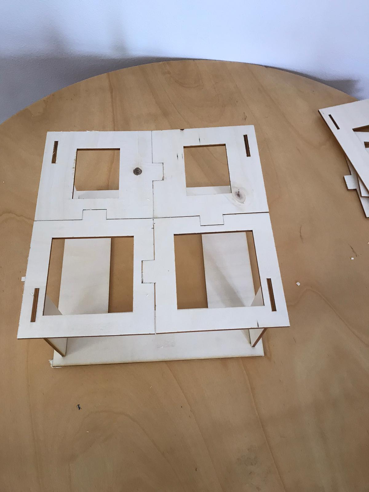
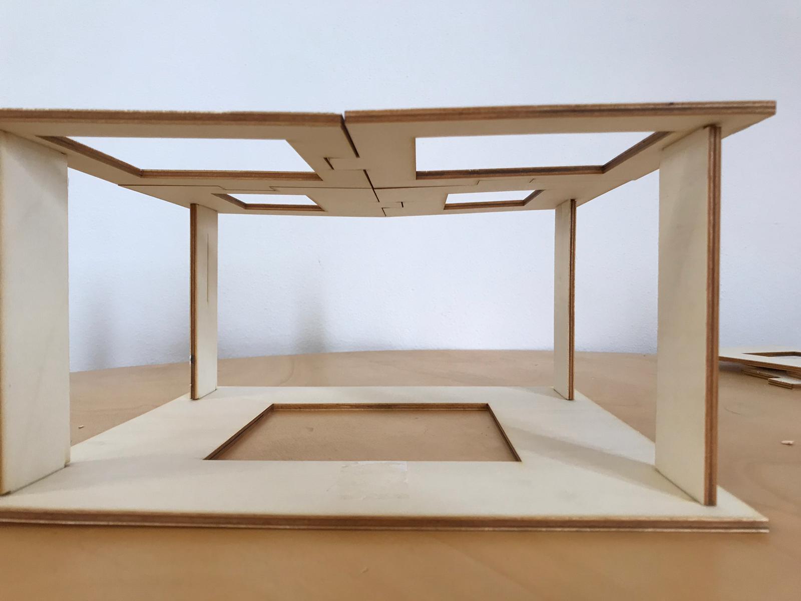
From this test I changed the kerf in all of my design to 0.11 mm and I cut again the kit. The result was good:
- In the next days I'll cut again my construction kit.
- I will improve my skills on Onshape.
- I will work on Fusion 360 and xDesign.
To make the 3D model downloadable I used Sketchfab. I created a free online account with which I can make my models public and get an embedded code too.