Week 6 - Electronics Design
Assignment:
use the test equipment in your lab to observe the operation of a microcontroller circuit board
Students:
Olivia De Masi, Elena Racanicchi, Chiara DianaRegulated power supply
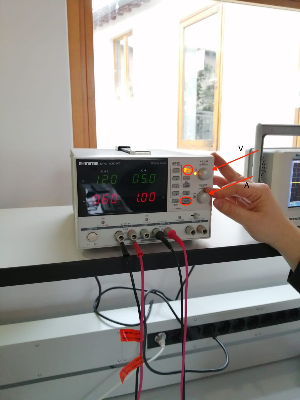
This tool equipment supplies current and it regulates the voltage of the current and the amperage (current value). We used it to provide current on one of our hello boards using the settings: 5 volts and 1 ampere. Using two jumpers we connected the black probe (negative) to the GND pin and the red probe (positive) to the VCC pin of the pinhead (the first pin is GND and the third one is VCC). The machine has two channels (be aware that the current flows in both channels at the same time), and two sets of probes, and we chose the first channel by pressing "CH1". We used the knob to adjust the voltage and amperage that we wanted. Be careful to press "output" to make the current flow.
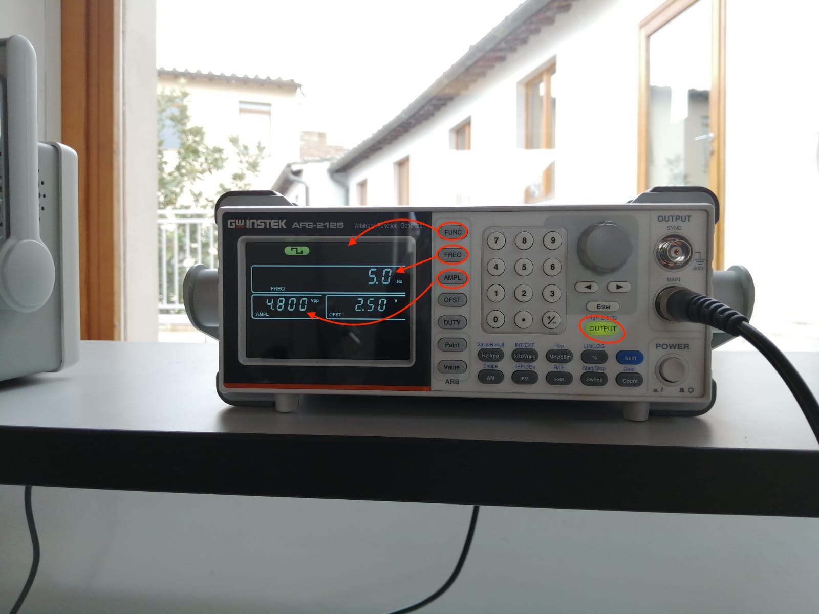
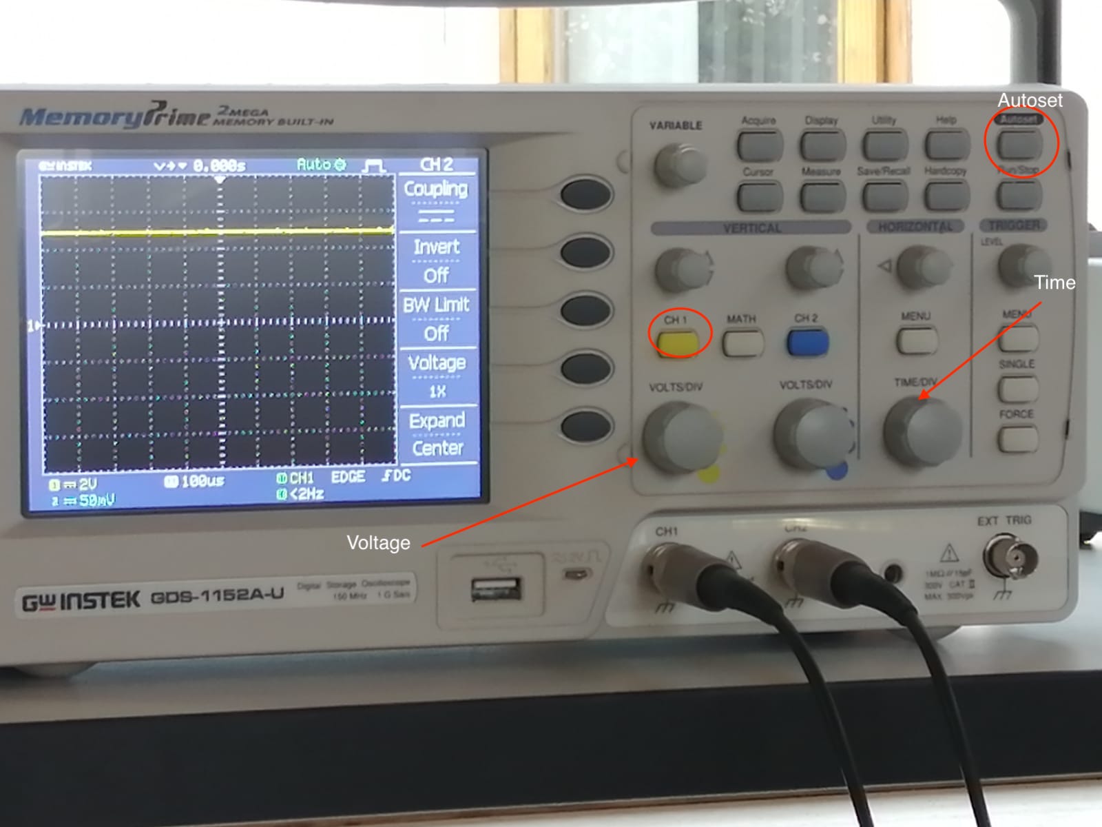
Oscilloscope
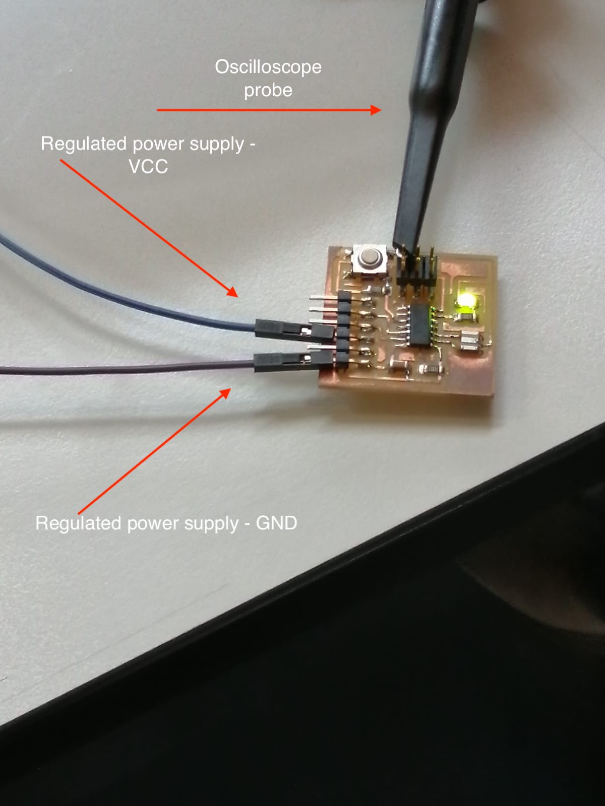
This tool helps analyze the electric signal of a component. It is very usefull in the debug process as it shows what's going on over a trace while current is flowing. It is provide with a so called "autoset" function: this way the machine will automatically set the best fitting parameters (time and voltage axes) to use. We used the oscilloscope with the regulated power supply to analize the signal of our hello board. This machine also has two probes (and so two channels 1 and 2) which must be connected to the component that we want to analize: in our case we connected it to the VCC pin of the avrISP to see how much current was flowing between the two VCC pins. The current is already flowing by 5 V and 1 A as we set, so we can see that the LED is blinking. The regulated power supply tells us how much amperage the LED is absorbing: it is usually 20 mA, infact we can see a swinging on the machine from 00.1 to 00.3 A.
Logic analyzer
The last tool that we used was the logic analyzer which simulates some of the functioning of the board. We can set a signal in the machine that we can then output on the board, infact it can also be used as a substitute of a component of our board.