Group Assignment:
1) Characterize the design rules for your PCB production process
Students:
Olivia De Masi, Chiara Diana, Elena Racanicchi
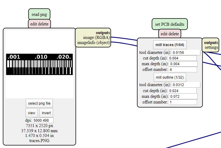
As a first step we saved the png files of the traces and outlines from the schedule.
We opened Mods and we selected the png we wanted and "mill traces" in the next mod:
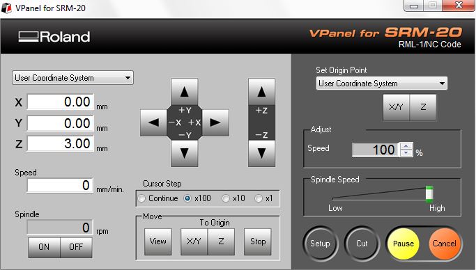
Now the settings are done automatically. The one thing we absolutely want to change are the origins (X,Y,Z) settings, which we want to take from 10 to 0:
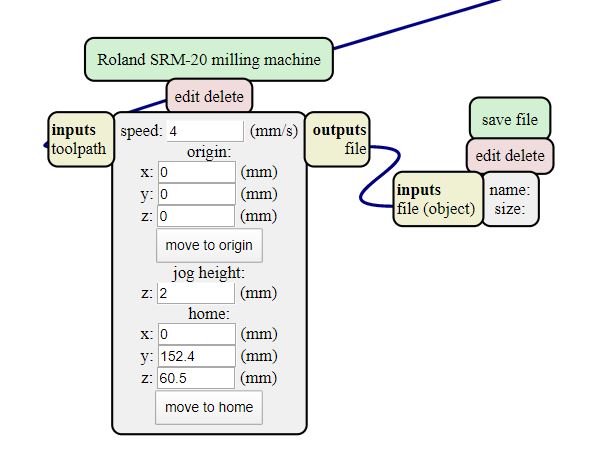
Now we need to take out the "Web Socket device" mod and substitute it with a "save file" one, so we delete it and then right click at the top left: module, open server module, file save. This way we can connect our origin mod with our newly made "save file" mod just by clicking on one and then on the other.
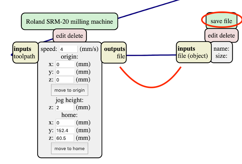
Now we can click on "calculate" and the file .rml will be downloaded on the pc.
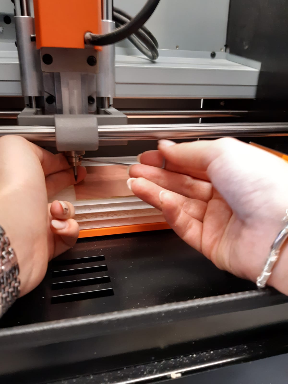
It's finally time to get our hands on the milling machine. The lab has a Roland SRM-20. As a first thing our instructor showed us how the chuck works and the different kinds of endmills.
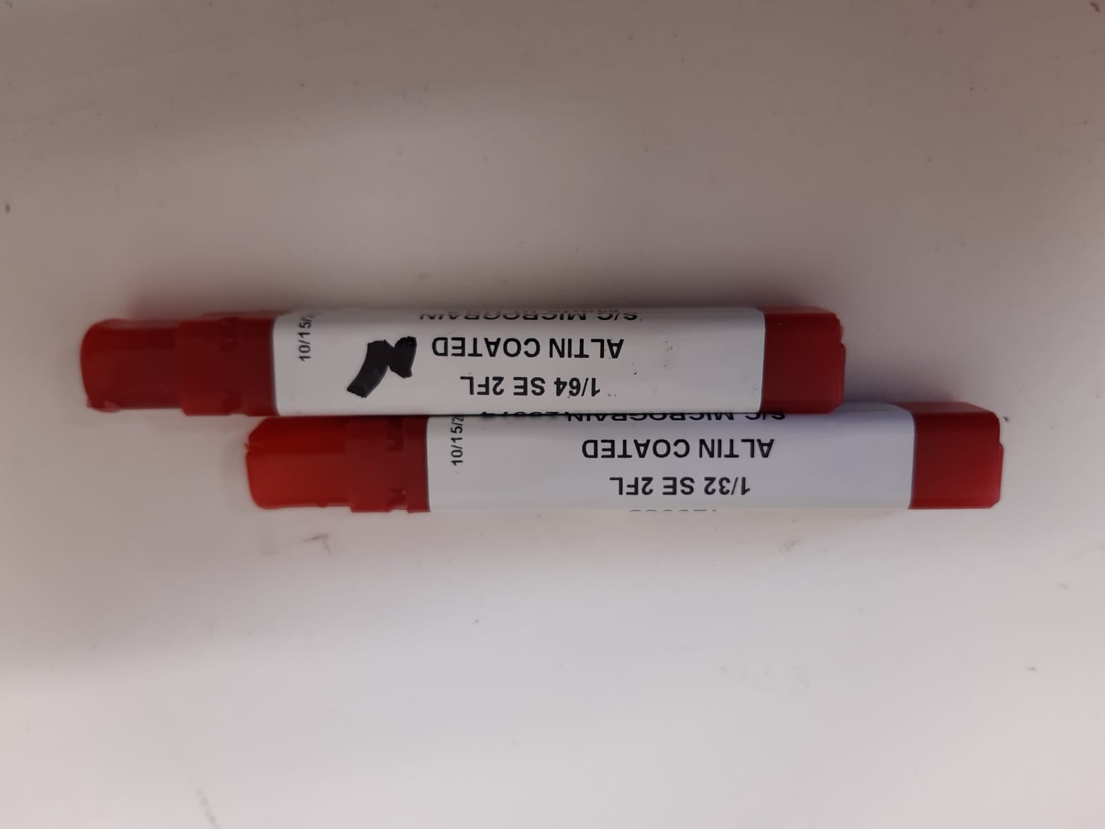
We have to mill the traces using a 1/64 inch endmill and the outlines using a 1/32 inch endmill.
After setting the copper board, securing it using some doubletape stick, we have to set the origins (X,Y,Z) on the milling machine. For the X and the Y we moved the machine's table forth and back to find the right
place where we wanted to start milling. On the machine's pc interface we set the origins. To find the Z's origin we installed the endmill in the chuck,
then we moved the chuck downwards untill it was very near the table, then we used the hex wrench to loosen the tip, make it touch the table
holding it firmly and then tight it up again.
Then we set the origin using the machine's interface as we did for the X and the Y:
With the command "cut" we we're able to select the file and mill the board. This is our result:
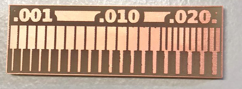
From our test we were able to characterize the design rules for our PCB milling machine Roland SRM-20:
- 0.16 inch is the minimum space that the 1/64 endimill can cut between the traces
- 0.001 inch is the tiniest trace that the same endmill can cut.