_________ COMPUTER-CONTROLLED MACHINING _________
GOALS:
- GROUP ASSIGNMENT:
Test runout, alignment, speeds, feeds, and toolpaths for your machine
- INDIVIDUAL ASSIGNMENT:
Make (design+mill+assemble) something big
| 3D DESIGN (FIRST MODEL) |
For this week's project, I decided to design a doghouse for my precious dog Chester.
I have a spacious garden at home, but Chester never had an outside doghouse and he's almost 3 years old. So I decided to build one for him.
I started analyzing the cons of this project, and one issue I encountered was that the majority of doghouses design I had found used nails to keep the stability of the house.
But I have to use joints instead, so it was a bit challenging finding what kind of joints could I use.
Another issue I could think of was, as usual, the size.
My dog is an adult Golden Retriever. After measuring his length and height, I came up with the minimum size for the Housedog base: 120x90 m.
I am not gonna lie. I was concerned by the size, giving that the material I could use was an OSB wood board 1.25x2.00 m, with 1.5 cm of thickness. But still, with the suggestions of the Instructor Simone Guercio, we concluded that I could do just the structure of the housedog, without the walls, and then cover it with some kind of waterproof material.
To simplify the design, I divided it into 3 parts:
- Base
- Columns
- Roof
_________________________ BASE _________________________
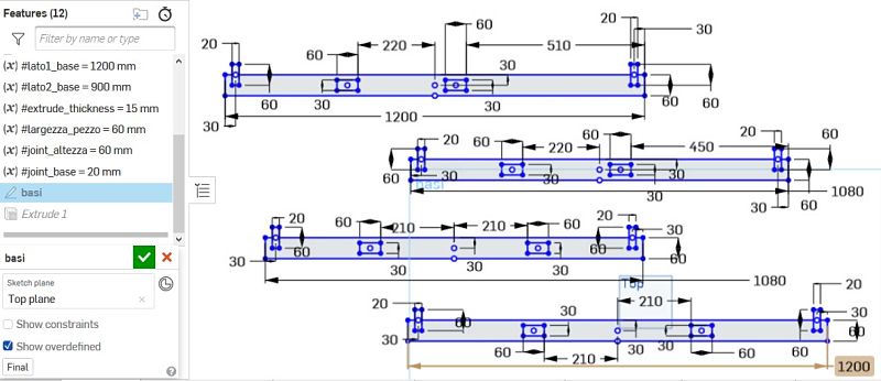
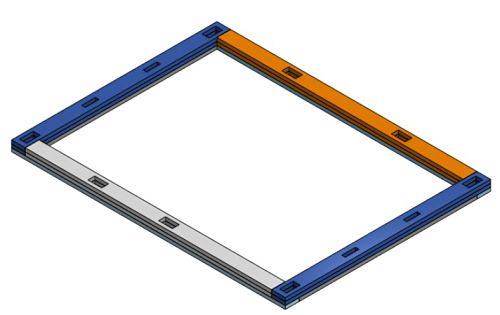
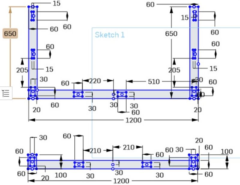
Starting from the base. I designed 3 layers because considering that the thickness of the material I will use is 1.5 cm, it would be too thin for holding the columns. With three layers instead, the hole would be 1.5x3 (4.5 cm) and that deepness would increase stability of the columns.
I also decided to joined the 4 pieces of first layer together with joints (you can clearly see it on the base_button image).
Having this idea in my mind, I began drewing the sketch on Onshape.

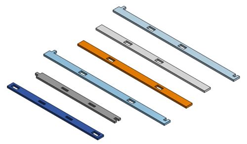
Here there is the Assembly Top view:
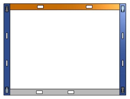
Here there is the view from the button:
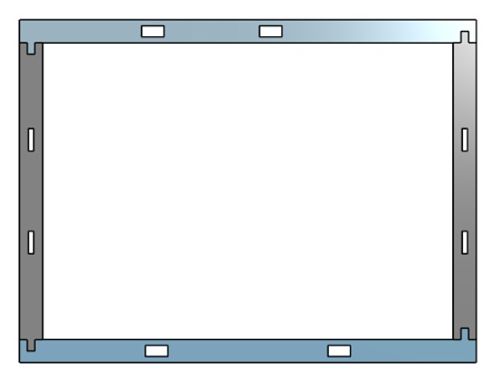
Here there is the isometric view:
_________________________ COLUMNS _________________________
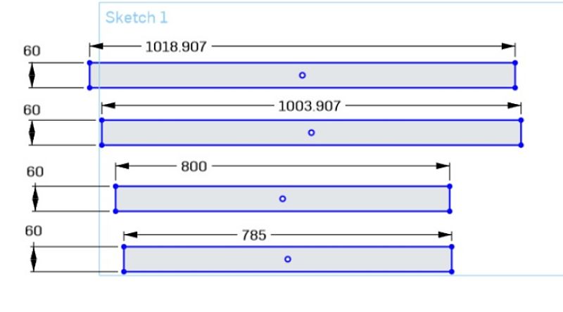
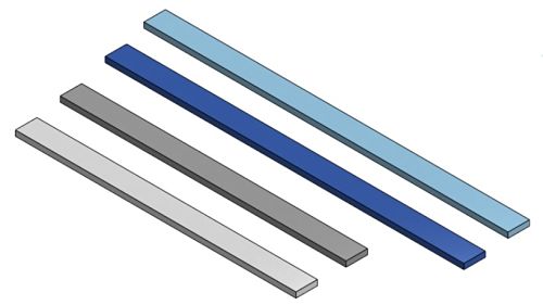
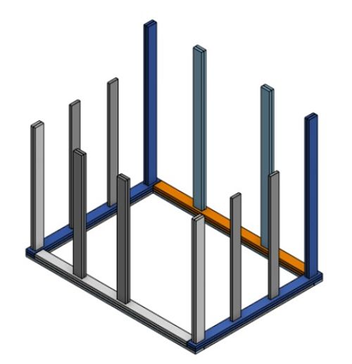
Then I proceed with the columns:
_________________________ ROOF _________________________
Firstly, I designed the base of the roof, to put it above the upper-part of the columns.
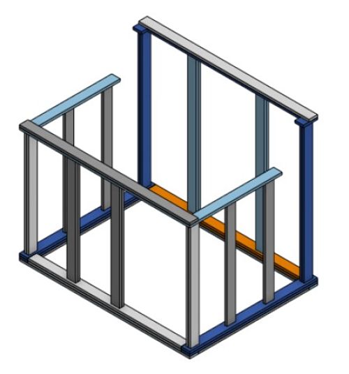
Then I designed the pieces for the structure that will hold the roof.
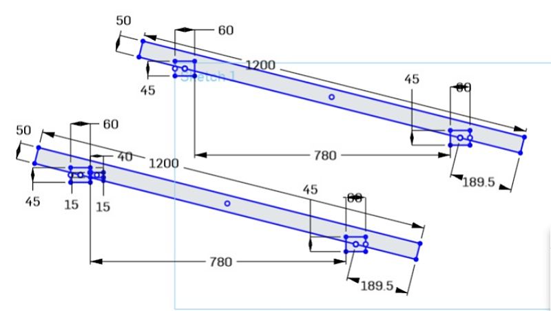
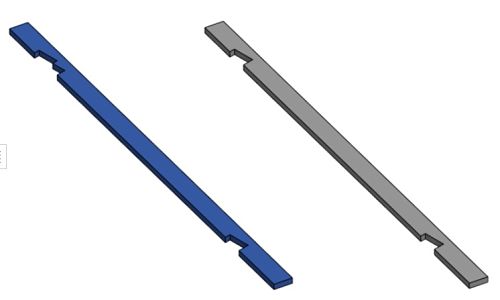
And this was the final result:
| 3D DESIGN (FINAL MODEL) |
Since the doghouse project would have more than 40 individual pieces that I have to polish, It would take to much time, so I decided to opt for an easier project: a desk with two shelves.
I designed it on Onshape. First the desk itself(40x80cm):
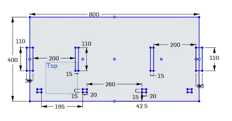
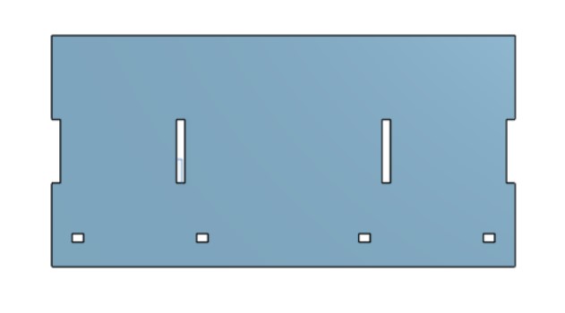
Than the four columns:
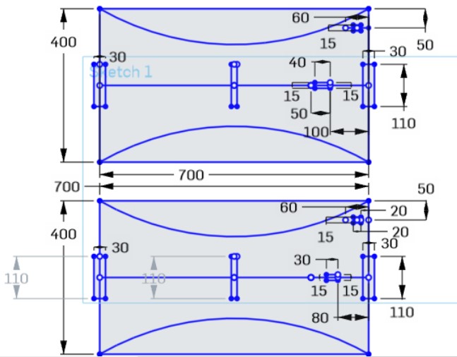
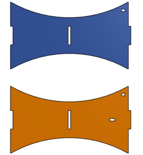
And lastly, the shelves and two supports to hold the culumns:
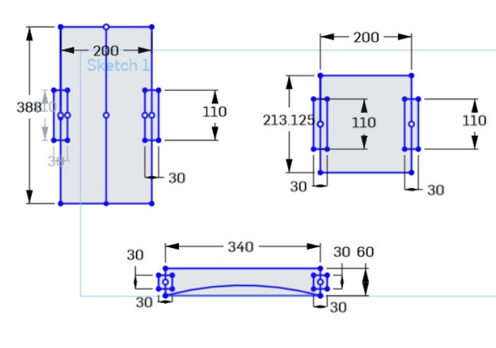
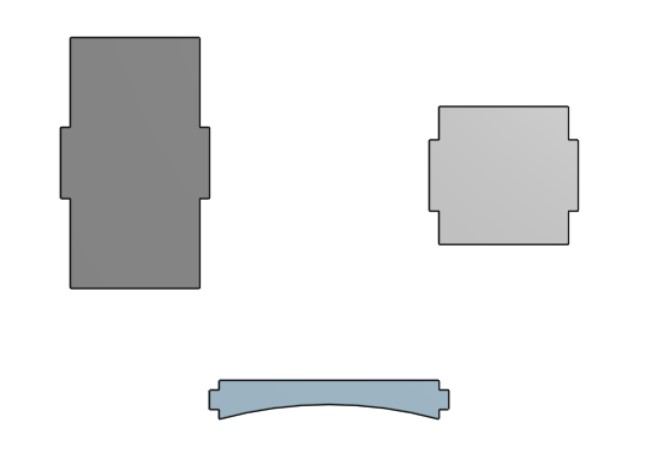
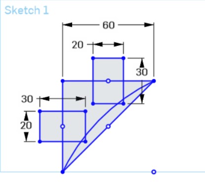

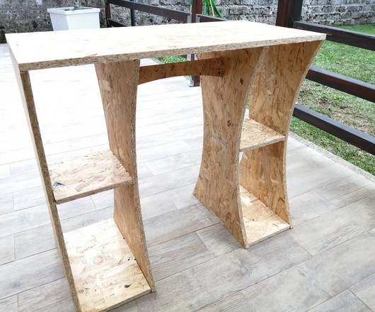
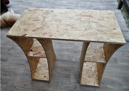
After assembling everything, this was the final result:
| VCARVE-PRO SOFTWARE |
For creating the G-Code file for the Shopbot I used VCarve software.
After opening the software I create a new file by clicking on the file dropdown icon.
REMEMBER to not click on the new file form the main manu because it is bugged.
______________ WORKSPACE/DESIGN AREA _______________
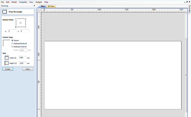
First of all, I designed the workspace area using the rectangular shape icon from the V-carve menu.

Since I had to take into consideration that the sacrificial layer of the shopbot is a little bit smaller (1220x2400 mm) and it would be better if the cut remains inside that perimeter. I created another rectangular shape with the sacrificial layer size inside the first one.
1.IMPORT VECTORIAL FILES (DXF)
Then I started imported the DXF files of my project into the software using the import vectorial files icon.

2.JOIN VECTORS
After selecting the shape, I clicked on join vectors
 to merge the shape lines.
3.GROUP OBJECT
After selecting the objects with internal shapes, I selected the group object icon.

4.MOVE OBJECT
After merging and grouping the objects, I started to move them onto the designed work area with the move icon.

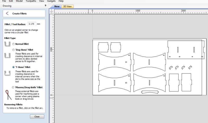
5.CREATE FILLET
After all the pieces where correctly positioned onto the workarea, it was time to create the fillet
 by clicking on the apposite icon.
Fillet/tool radius: depends on the cutting tool that you are using. I used an 1/4 iches (6.35mm) cutdown end-mill, so its radius was 3.175 mm.
As a fillet type, I decided using the 'T-bone' fillet because creating clearance in internal corners would help assembling the pieces together.
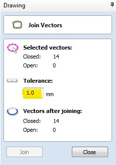
At first the software didn't allow me to do the fillet on some pieces, expecially the columns. With the help of the instructor, after looking around some settings I found that the tolerance parameter could influence into VCarve not recognising those angle as 90°, so I clicked again on the join vectors icon and change the tolerance parameter from 10mm to 1mm.
Moreover, I also found that doing the t-bone fillet with ungrouped pieces works better. After doing the fillet you can group them again.
This is an example of T-Bone fillet:
_______________ POCKET CUT FOR THE SCREWS ________________
Instead of finding a position for the screws manually and check it while moving the spindle after, I decided to position the screws directly onto the V-carve design on do a pocket cut for them.
I created 5 circle with the circle shape icon and positione them onto the work area.
I selected all of them by clicking on their shape lines while pressing shift.
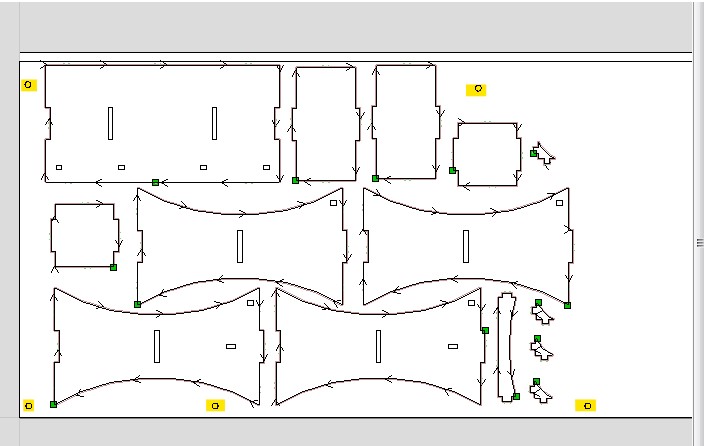
Then I opened the toolpath on the top-right corner of the screen and selected pocket toolpath, editing the following settings as the picture below shows.
I used the same endmill settings that we found during the group assignment.
This was the toolpath preview.
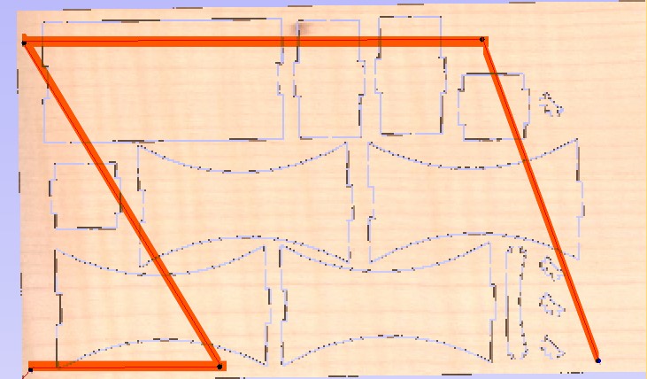
Once I had the G-Code file and the wood board positioned, I set X,Y,Z axis into the Shopbot command console (the machine was already turned on and had already completed the spindle warm-up routine), I inserted the G-Code file and began the cut.
I noticed that something wasn't wright when, after doing the first pocket, the spindle moved on the next pocket while the endmill was scratching the wood board. With my istructor Simone Guercio I immediately stopped the cutting to see what had happened.
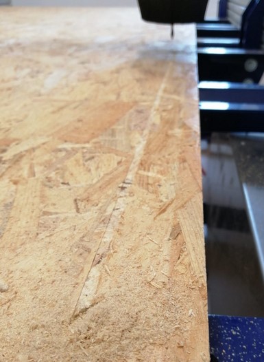
We saw that in that point (right corner angle) the wood board was bent and lifted more than usual ( I didnt' use screws for the pocket cut since the board weight was enough), so the Instructor speculated that the safe height wasnt'enough and needed to be edited.
So, I went to Material setup-> Rapid Z Gaps above Material and changed both Clearance and Plunge from 2mm to 10mm.
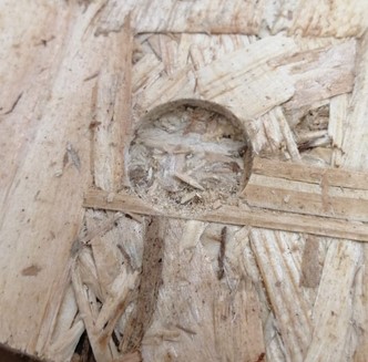
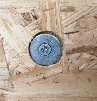
This was the result after removing the material residue. After doing it, I proceded tightening the screws.
________________ 2D PROFILE EXTERNAL CUT __________________
Once the wood board was secured with screws, I proceed doing on Vcarve the toolpath for the external cut. I selected the external shape of the pieces and clicked on the profile cut toolpath.
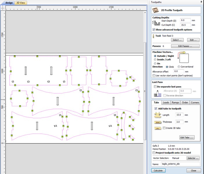
I used the same endmill settings as I did with the pocket cut. I just changed the feed rate from 80 to 90.
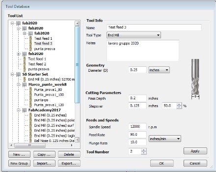
Since it was anf external cut, I selected the Outside/Right Cut on the Machine Vector setting.
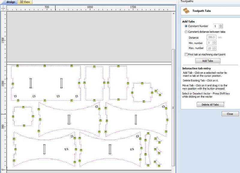
Than I proceded creating the tabs (length = 15 mm, thickness = 3mm) and I calculate the toolpath.
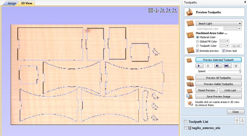
And selecting the toolpath preview tool.
________________ 2D PROFILE INTERNAL CUT _________________
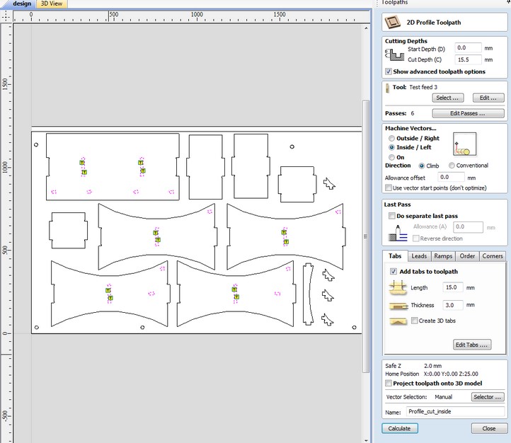
For the internal cut I followed the same procedure by selecting the internal parts, creating the tabs and doing an inside/left cut on the Machine Vectors settings.
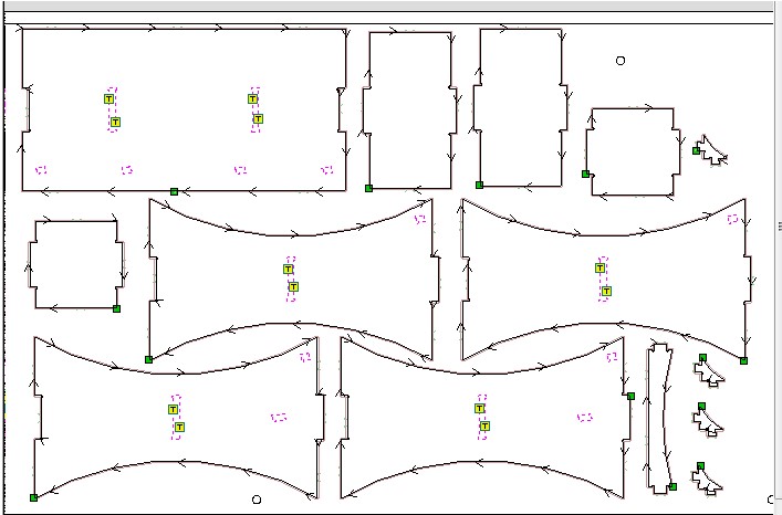
After saving the external and internal cut toolpaths separately, I imported the files into the Shopbot command console and started the cutting of the internal cut before and then the external one. It took about an hour to complete the cutting and the result was this:
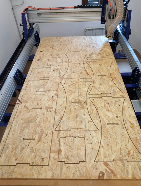
________________ FINAL ASSEMBLY _________________
After hours and hours spent on polishing and levigating the pieces with the help of a file for wood, sand paper and Dremel, I started to joining the pieces together using a rubber hammer. It took me an entire morning to assembly everything, but at the end it was so worthy.
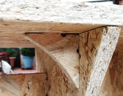
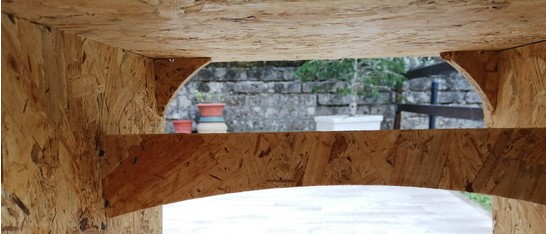
I really liked how the design turned out. Here there are a couples of photos:
