________________ INPUT DEVICES _________________
GOALS:
- GROUP ASSIGNMENT:
Probe an input device(s)'s analog and digital signals
- INDIVIDUAL ASSIGNMENT:
- Measure something: add a sensor to a microcontroller board that you have designed and read it.
| ARDUINO GROVE KIT |
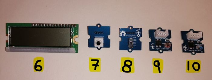
Due to the Coronavirus lockdown happening here in Italy, I can't have access to the lab, so the instructor sent me an Arduino Grove kit (that uses the Grove System developed by Seeedstudio) with different types of sensors I could experiment.The kit contained:
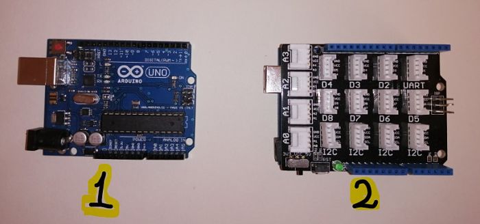
- Arduino one
- Arduino one + grove base shield
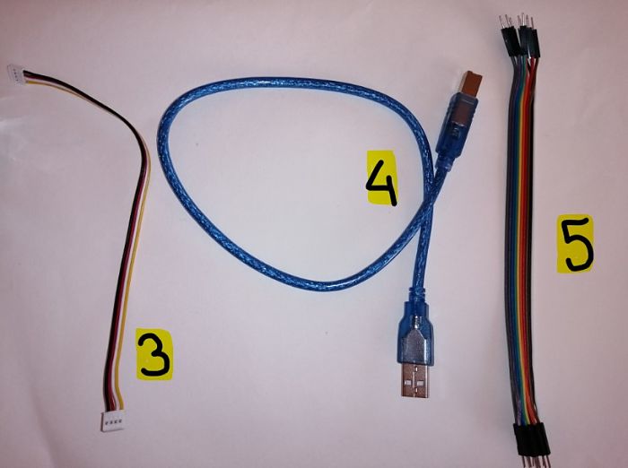
- Grove to Header Pin Converter (Project Examples)
- USB cable
- jumpers cables
- lumex LCD Display
- button 1.1
- Switch(P)
- light sensor v1.0
- temperature sensor v1.0
- touch sensor v.1.0
- led socket (light sensor v1.2)
- buzzer v.1.1
- rotary angle 1.1
- Keyes RGB color sensor

________________________ BUTTON _________________________
I used the grove-button reference on wikiseed.studio as a guide for both the hardware (connecting the sensor to the Arduino grove port) and the software part (Arduino code on the Arduino software IDE).
HARDWARE
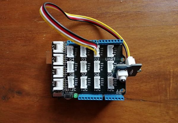
Since the button is a digital input, I connected it to the digital port D2 on the grove base shield using the 4-pin grove cable.
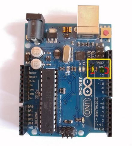
For the led, I used the incorporated led on PIN 13 of the Arduino board ( it is the only actuator built-in to the board).
The last step was connecting Arduino to the PC by using a USB cable.
SOFTWARE
The first thing you want to do once having downloaded and installed the Arduino Software IDE is to set the correct serial port and Arduino board.
So, from the upper toolbar I selected:
Tools -> Board:"Arduino One" and Port -> COM3.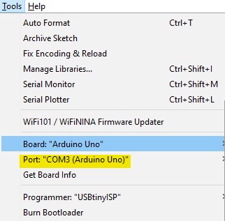
I copied the code from the grove-button reference on wikiseed.studio, I pasted it into the Arduino Software IDE, verified it with
 and upload it with
  .
.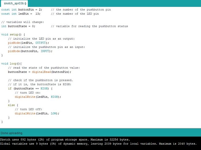
Every time I pressed the button, the led turned on.
__________________ TEMPERATURE SENSOR __________________
I used the grove-temperature reference on wikiseed.studio.
HARDWARE
Temperature sensor is a analogic input, so I connected it to the Analog Port A0 on the Grove base shield.
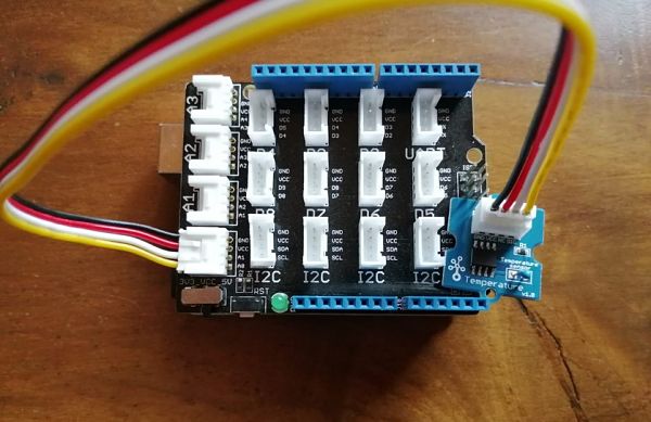
SOFTWARE
I copied the sketch from grove-temperature sensor reference on wikiseed.studio, and I pasted it on Arduino IDE sketch.
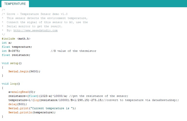
When I was holding the sensor the temperature rose, checking the signal every 200 m/s. Meanwhile on the computer screen I could check the readings via the Serial Monitor.
_____________________ LIGHT SENSOR ______________________
For the light sensor Grove module, I followed this tutorial on youtube by Javier Martinez.
HARDWARE
On the Grove-base shield, I connected the analogic input of the light sensor in A0 port, and the LED digital output in D7 port.
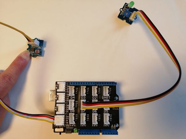
SOFTWARE
Following the tutorial instructions, I wrote the code on Arduino IDE, verified it, and upload it.
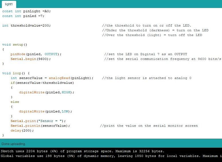
As a result, when the sensor was exposed the light exposure was above the threshold (light) and the LED was off. But, when I covered the sensor with my hand, the light exposure went under the threshold (darkness) and the LED turned on.
Meanwhile, on the serial monitor I could see the value of the light exposure.
_____________________ TOUCH SENSOR _____________________
I used the grove-touch sensor reference on wikiseed.studio.
HARDWARE
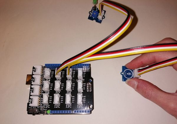
I connected the touch sensor, as a digital input, in the D2 port, and the LED sensor, as a digital output, in the D3 port of the Grove base shield.
SOFTWARE
I copied the sketch from grove-touch sensor reference on wikiseed.studio, and I pasted it on Arduino IDE sketch.
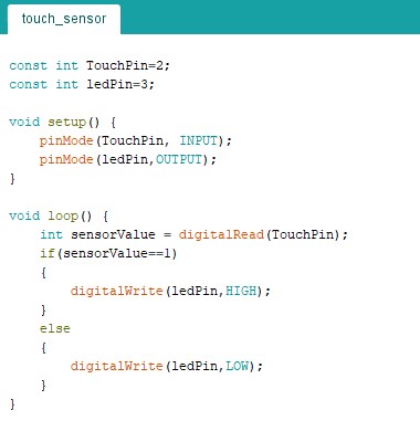
This was the result: everytime I touched the sensor, the led turned on.
| PCB DESIGN |
_____________________ NTC THERMISTOR ______________________
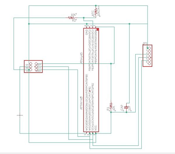
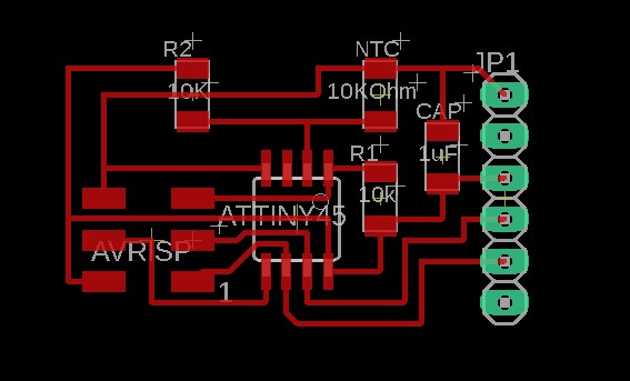
I decided to do an NTC thermistor with the ATtiny45.
Durign the PCB design, instead od doing a Wheatstone Bridge as Niel's board, I did a simple voltage divider with a 10kOhm resistor (since I knew that I would use a 10kOhm NTC thermistor).
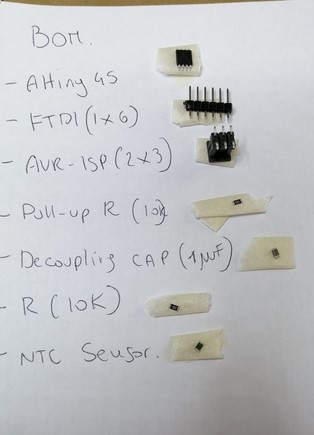
The other components used were:
- Pull-up 10k resistor
- Decoupling capacitor (1 uF)
- AVR ISP 3x2
- FTDI (1x6)
| MILLING & SOLDERING |
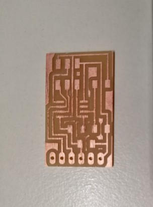
Here there is the milled board.
Here there is the list of all the needed components for stuffing the board.
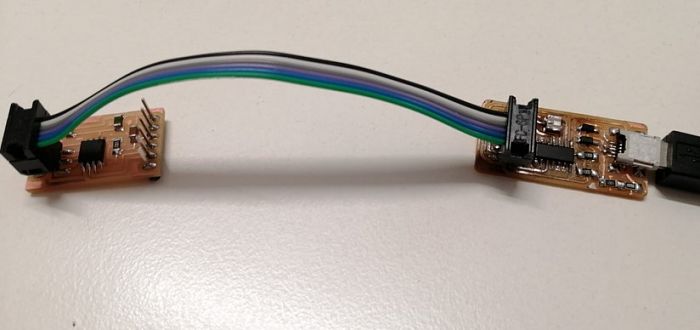
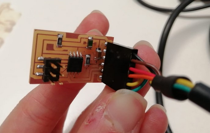
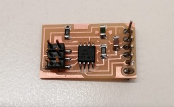
Here is the final, soldered board.
| PROGRAMMING |
Since the ATtiny45 doesn't have Serial Communication pins, I used the Arduino SoftwareSerial Library to allowing serial communication to take place on the other digital pins of the board. In my case, was replicating the fuctionality of RX, TX on my PB2, PB1 pins.
Initially, I wanted to serial printed the actual temperature value in C°, but the Attiny45 memory storage wasn't enough to compile the sketch, so I commented all those lines and simply serial printed the thermistor value.
I connected the board through my programmer and after the sketch was uploaded, I used an FTDI cable.
