____________ 3D SCANNING AND PRINTING ____________
GOALS:
- GROUP ASSIGNMENT:
Test the design rules for your printer(s).
Document your work and explain what are the limits of your printer(s) (in a group or individually)
- INDIVIDUAL ASSIGNMENT:
- Design and 3D print an object (small, few cm3, limited by printer time) that could not be easily made subtractively.
- 3D scan an object, try to prepare it for printing (and optionally print it).
| 3D SCANNING |
____________________ PHOTO-SHOOTING ____________________
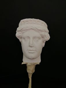
For the 3D scan assignment, I decided to use a 3D printed head, allegedly attributed to the Italian sculptor, Nicola Pisano.
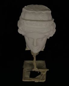
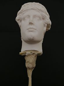
I used a structure to elevate the head and a black bristol-paper as a background for the photo-shooting session, so that the outline of the sculpture was highlighted and easily recognized by the photogrammetry software on a later stage.
I took lots of photos, 94 to be honest, with my phone (remember to set a low ISO), going 360° around the object, searching different angles, points of view, and highlighting important features of the sculpture.
During the first photo session, the camera was at 0°, in the second photo session was 45° upper 0°, and the final session was 45° below 0°.
_______________________ METASHAPE _______________________
Once I had collected all of my photos, I imported them into Agisoft Metashape, a photogrammetric processing of digital images and 3D spatial data generation.
By clicking on "Chunk1 -> Add -> Add photos".
This step is really important because you can see how many of your photos the software have recognizes as valid and useful. In my case 88 photos out of 94 were properly recognised by the software.
Then I clicked on "Process -> Align photos" to initiating the process in which Metashape finds the position and orientation for each photo and builds a sparse point cloud model.
Delete the extra points that you don't need by clicking on the rectangular shape on toolbar, higlighting the section of the points you want to delete, and pressing "Canc".
After that, I clicked on "Process -> "Build dense cloud" to generate and visualize a dense point cloud model by calculating depth information for each camera position.
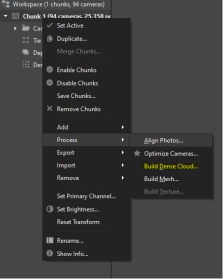
The last step was clicking on "Process -> "Build mesh" to reconstruct a polygonal model - mesh, based on the information acquired with the prior steps.
Once the mash building was completed, a model shaded, like the image on the bottom left, appeared. I changed it to "Model solid".
I finally exported the STL file, and imported it to Meshmixer to check it up.
____________________ MESHMIXER ____________________
I imported the STL file in Meshmixer for three basic reasons that I am going to explain in the following paragraphs:
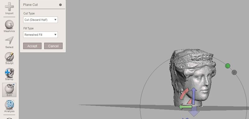
Plane cutting a portion of the neck
From the vertical toolbar on the left side, I clicked on "Edit -> plane cut", to cut out a portion of the model's neck.
Smoothing the surface with brushes
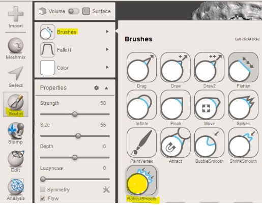
From the toolbar select "Sculpt -> brushes -> Robust smooth"
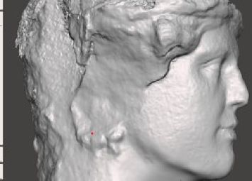
Here the before and after smoothing:
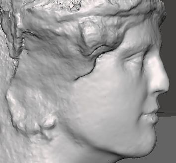
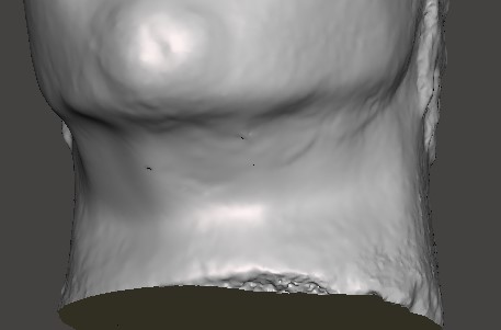
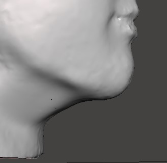
Inspector
Checking with Inspector that the shape was completely sealed, for a final approval.
"analyis -> Inspector -> Auto repair -> Done".
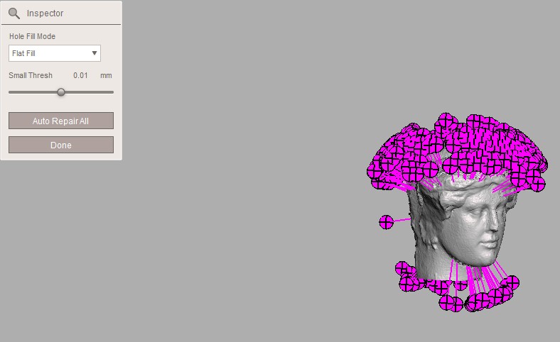
You can see a preview of the final object down below.
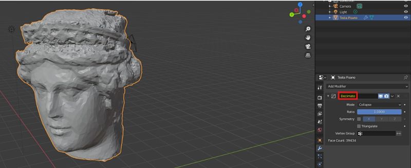
Since the original STL was 37 MB, I compressed it using the "Decimate" option in Blender. First a Decimate 0.3 = 11.8 MB, and then a Decimate 0.05 = 1.87 MB.
The 3D image obviously lost quality, but you can download the original STL from sketchfab if you want.
| 3D PRINTING |
______________________ ONSHAPE ______________________
This week I was also introduced to 3D printing process.
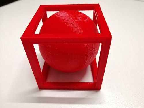
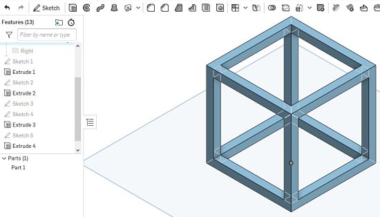
Form my 3D print assignment, I decided to do a sphere inside a square with opened faces.
This construction cannot be made subtractively because the diameter of the sphere is bigger than the sides of the square.
Firstly, I designed the square on Onshape.
And then, I created the sphere with the following passages: 1. I created a sketch in the "Front plane" with a center point circle and a line coincident and perpendicular to the center of the circle.
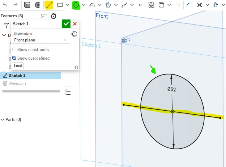
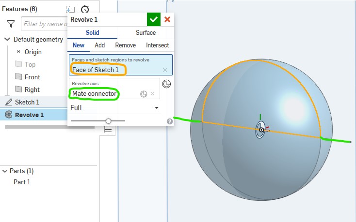
2. I selected "Revolve" from the tool bar, then I selected "faces and sketch regions to revolve" form the Revolve1 window and I clicked on the semicircle highlighted in orange in the image below.
Then, I clicked on "Revolve Axis", highlighted in green, and selected the color matching line, as our axis.
In this way a sphere should have appear.
Here was my final object:
____________________ MESHMIXER ____________________
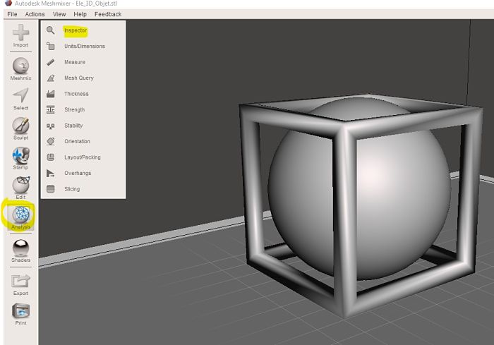
After exporting the shape as an STL file form Onshape, I imported it into Meshmixer, a free 3D modeling software, to check that the shapes were completely sealed.
From the tools menu on the left, we clicked on "Analysis" and then on "Inspector".
For a further inspection, I also clicked on "auto-repair" and done.
After exporting the object as an STL format, It was ready to be imported on Ultimaker Cura.
_________________ ULTIMAKER CURA 4.5 _________________
I imported the STL file on Cura and I changed the following setting:
- Layer height: 0.2
- Wall thickness: 1.2
- Z seam Alignment: Random
- infill density: 17%
- print speed: 100 mm/s
- Generate support: Everywhere
- Build plate adhesion: Brim (0.8)
This was the preview that cura offered:
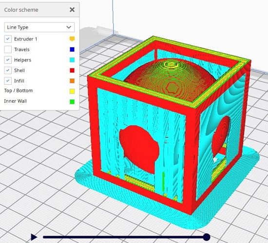
After checking that all the support were in the correct position. It was time to 3D printed the object.
This was the final result:
