_____________ ELECTRONICS PRODUCTION _____________
GOALS:
- GROUP ASSIGNMENT:
Characterize the design rules for your PCB production process: document feeds, speeds, plunge rate, depth of cut (traces and outline) and tooling.
- INDIVIDUAL ASSIGNMENT:
Make an in-circuit programmer by milling and stuffing the PCB, test it, then optionally try other PCB fabrication process.
| MILLING |
________________________ MODS ________________________
For my in-circuit programmer, I chose the
AtTtiny44 of Ali (FabOptimus) from the schedule documentation.
I downloaded the "png" image of the traces and the outline.
The new CNC machine I was introduced this week, the Roland Milling SRM-20, works with files in "rml." format,
so I used mods to convert my "png" images to that format.
Firstly, I had to import my png. image.
From the menu window, click on "program - open server program - Roland mill SRM-20 PCB png."
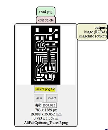
A page with lots of modules should have appeared. Most of them are preset modules and you need to change just a few things. In the "read png" module, for example, you simply import your png file (always check the "dpi" resolution of the image. It should be around 1000 inch)
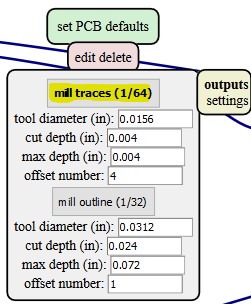
In the module "set PCB defaults" you have to select the defaults according to the png file you had previously imported. If it was the traces, you select "mill traces 1/64". If the png file was the outline, you must select "trace outline 1/32".
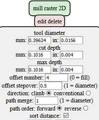
According to which one you have selected, You will see that the following module, "mill raster 2D" will automatically change to the correct parameters.
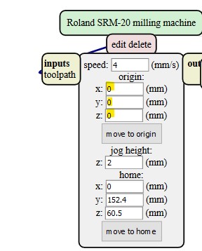
In the module "Roland SRM-20 milling machine" be sure you have set the origin x, y, z to 0.
Once you have completed all the previous passages, click on calculate from the "mill rester 2D" module and the file image in rml format will appear.
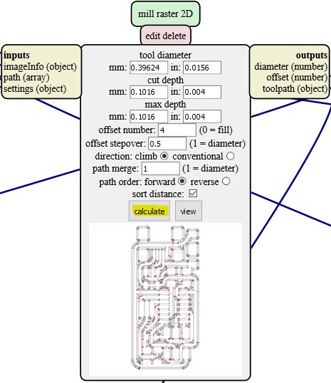
Depending on the browser you are using, a window for automatically saving the file should be opened, but if not, you have to save the file manually.
After deleting the "Web socket device" module, you have to add a "save" module.
Click on the bar icon in the top left of the page then click on the module - open server module - file: save.
A module like the one in the image below will appear. Now you simply have to connect the input of the save module to the output of the "Roland SRM-20 milling machine".
WATCH OUT:
in order to connect the modules you must click on "file (object)" from the input module and "file" from the output module. Do not simply click on input and output. And do not click twice on the same module, otherwise, you are going to connect a module with itself.
_____________ MACHINE EQUIPMENT AND SETTINGS _____________
First of all, you have to check that you have brought all the essential equipment for the milling process which includes:
1. A 1/64 ich flat endmill (for the PCB traces).
2.a 1/32 inch flat endmill (for the PCB outline).
3. A hexagonal wrench to tight the set screw after having insert the tip in the head spindle.
4. A lever to detach the PCB from the table.
5. A brush to remove all the residues and dust once the milling process is completed.
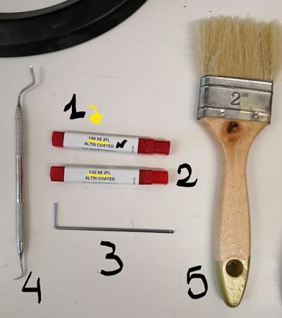
In addition, you should also bring a double-stick tape to attach the material to the table.
Once you have gathered all the needed tools, stick the double-stick tape to the material and attached it onto the milling table (be sure to press it with your fingers to check if it is totally stuck to the table.
This step is really important because it prevents the material from moving during the cutting.
Having set the material, you can now insert the 1/64 inch endmill (you must start the cutting from the traces and then moving onto the outline) into the head spindle and use the hexagonal wrench to tight the set screw.
Now you are ready to set your origin axes (x,y,z) from the machine Software.
_________________ V-PANEL FOR SRM-20 _________________
The Roland SRM-20 is connected to the computer through a USB cable and it needs a specific software, V-panel for SRM-20, to operate.
The software interface is organized as the image below shows.
The first thing you need to do is set the origin (X and Y) by moving the table and the head spindle using the keypad.
Once you have moved the cutting tool in the desired position, click on "XY" in the "set origin point" menu on the right side of the panel.
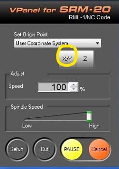
Having set the origin points (XY) means that those parameters will now appear as 0 mm.
Now, to set the Z, move the Z cursor button to approximate the tip to the surface of the material, then loose the set screw, make the tip touch the surface of the material, and tight the set screw again.
WATCH OUT:
remember to hold firmly the cutting tool with two fingers while tightening the set screw, otherwise, the tip will go slightly up and it will end up not touching the material and not cutting at all.
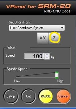
WATCH OUT:
After setting the Z, remember to move up the Z cursor button by 2 or 3 mm. This is really important because of the cutting tool needs to acquire the correct speed for cutting and if this procedure is done while the tip is touching the material, this will be ruined before the milling process has even started.
Once you have set X, Y and Z you are ready to import your rml traces file.
Click on "cut"- "add" file and then "output" to start the milling process.
Once the traces are all cut you must follow the same procedures with the outline file.
At the end of the day this was my final result:
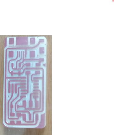
As you can see, some traces in the first attempted PCB weren't cut well, they were bigger and not straight. You can notice the difference if you compare it especially with the second PCB that I did, this one:
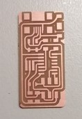
Our instructor said that, in his opinion, in the first attempt the material was not perfectly attached to the table and, as a consequence, it suffered minor change positions during the milling process, which eventually led to some skewed lines.
While listening to the instructor, I suddenly remembered that, in my first PCB, I had removed the stick tape too early.
So after 2 or 3 minutes, trying to find the best position for the material, the tape wasn't sticky enough and I placed it without pressing it too much on the table.
| STUFFING |
____________________ EQUIPMENT ____________________
Now that I had milled the base of my PCB it was time to solder all the components.
Let's begin with a list of all the equiment:
1. soldering iron
2. solder tip cleaning wire ( remember to use it frequently)
3. bill of materials (B.O.M)
4. soldering fume extractor/ dust collector
5. solder
6. solder wick
7. tweezers
8. stick tape
9. flux
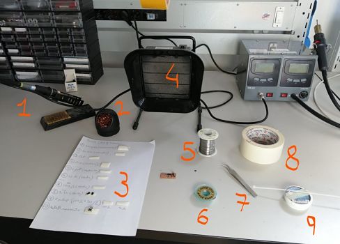
_____________ SOLDERING (TIPS AND TECHNIQUES) _____________
I have to admit that at the beginning I found soldering really hard, especially the first day, it was really frustrating.
But those hardships eventually led me to rethink about the technique I had used, which was completely non-existent.
I realized that I didn't think about a proper strategy for soldering, other than starting form the central componenents, and doing the external ones at the end.
One of the first issues that I encountered was in fact how to proper use the soldering iron and the solder.
Without even realising it, I was moving the pen left and right while holding the solder, and as a consequence, the solder sticked just onto the iron and not on the components.
I did almost half of my board with this kind of improper technique and it was obviously a mess. Some of the components weren't attached, or just one part was attached, bubbles of solders here and there.
It took me all the next day morning to fix it, but after whatching lots of tutorials on youtube (there are a lot about soldering), I tried to solder the last components of my board (the USB connector and the diods) by holding the iron onto the material for a longer period (like three second, istead of just one) and then moving the solder onto the area I wanted to stuff.
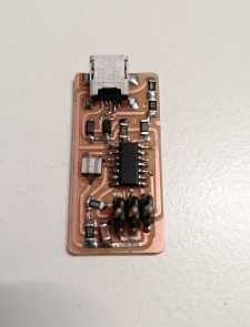
After lots of hours, this was my PCB board with all the solded components:
| PROGRAMMING |
Now it was time to program my board to make it a programmer.
As the FabAcademy tutorial said, to program the FabISP, I needed to accomplish five steps:
1. install the necessary software for your operating system and download the firmware.
2. Edit the Makefile
3. Set the fuses / program the board
4. Verify that the board is working properly
5. Open up the jumpers to make it a programmer.
Let's dive in into each step.
_____________ AVR TOOLCHAIN (WINDOWS 10) _____________
My operating system is Windows 10, and as the instructor explained to me, since the "Windows softwares/drivers install" for the AVR toolchain, in the fabAcademy tutorial was abandoned, we needed to follow another strategy for run the AVR toolchain.
To be precise, for programming my board with Windows 10, I needed:
- GIT (which i had already installed during the first week of fabacademy)
- a "make", downloaded from sourceforge .

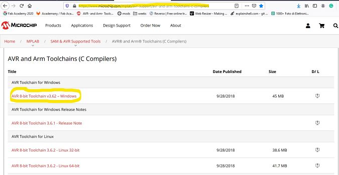
- an"AVR toolchain", downloaded from Microchip .
- avrdude downloaded from this windows avr tutorial
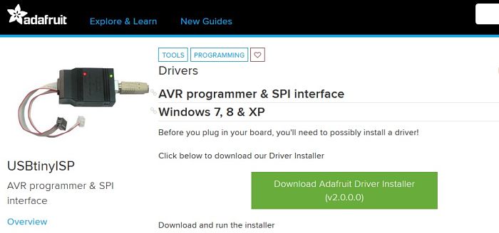
-drivers for programmer, downloaded from adafruit
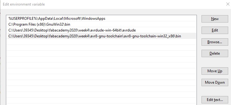
At this point you have to edit your path with the "make", "AVR toolchain" and "andavrdude" from "Control panel -> Control panel -> advance sistem settings -> environment variables -> path -> edit -> new -> browse (in browse you must serach the location of the folder you want).
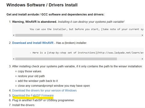
Download the firmware.
The firmware is the software that will program your PCB. You can download the firmware directely from the this fabacademy tutorial.
_________________ EDIT THE MAKEFILE _________________
Downloading the firmware, you download a "firmware.zip" folder. Extract all the files inside the zip with right click of the mause "Extract all", and after that you shoud have a "firmware" folder. Click on the folder, then on "fabISP_mac.0.8.2_firmware"-> "Makefile".
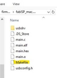
Open the "makefile" with your text-editor, and a page like this should appeared:
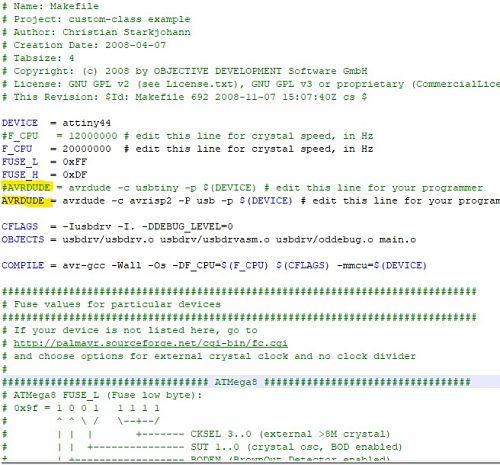
I was interested to change the higlighted lines. In particular, I wanted to change the comment(#) from the upper line, down to the following line. This because my PCB was an "attiny", ad not an "avrisp2".
Once I had inverted the "#", the two code lines looked like this.

At that point you must save the changes.
From the shell, insert the command "make -v", "avrdude -v" to stamp the content of the software.

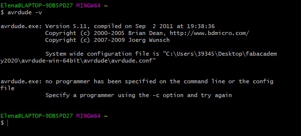
___________ SET THE FUSES/PROGRAMM THE BOARD ___________
Now i needed to compile the firmware.
I connected my PCB to a programmer, given by the istructor, trought a ribbon cable. And then I connect the programmer to my computer throught a USB cable. I checked that my computer could recognize the programmer, from Control panel -> system -> device manager. After that, from git bash shell, I went inside the "makefile" folder (fabISP_mac.0.8.2_firmware).
I wrote the command "make clean". Everything went smooth and I had a message like the following:
 Elena@LAPTOP-9DB5PD27 MINGW64 ~/Desktop/fabacademy2020/week4/firmware/fabISP_mac.0.8.2_firmware
$ make clean
rm -f main.hex main.lst main.obj main.cof main.list main.map main.eep.hex main.elf *.o usbdrv/*.o main.s usbdrv/oddebug.s usbdrv/usbdrv.s
After that, I typed "make hex", and everything was ok.
 Elena@LAPTOP-9DB5PD27 MINGW64 ~/Desktop/fabacademy2020/week4/firmware/fabISP_mac.0.8.2_firmware
$ make hex
avr-gcc -Wall -Os -DF_CPU=20000000       -Iusbdrv -I. -DDEBUG_LEVEL=0 -mmcu=attiny44 -c usbdrv/usbdrv.c -o usbdrv/usbdrv.o
avr-gcc -Wall -Os -DF_CPU=20000000       -Iusbdrv -I. -DDEBUG_LEVEL=0 -mmcu=attiny44 -x assembler-with-cpp -c usbdrv/usbdrvasm.s -o usbdrv/usbdrvasm.o
avr-gcc -Wall -Os -DF_CPU=20000000       -Iusbdrv -I. -DDEBUG_LEVEL=0 -mmcu=attiny44 -c usbdrv/oddebug.c -o usbdrv/oddebug.o
avr-gcc -Wall -Os -DF_CPU=20000000       -Iusbdrv -I. -DDEBUG_LEVEL=0 -mmcu=attiny44 -c main.c -o main.o
main.c:88:13: warning: always_inline function might not be inlinable [-Wattributes]
 static void delay ( void )
             ^
avr-gcc -Wall -Os -DF_CPU=20000000       -Iusbdrv -I. -DDEBUG_LEVEL=0 -mmcu=attiny44 -o main.elf usbdrv/usbdrv.o usbdrv/usbdrvasm.o usbdrv/oddebug.o main.o
rm -f main.hex main.eep.hex
avr-objcopy -j .text -j .data -O ihex main.elf main.hex
avr-size main.hex
   text    data     bss     dec     hex filename
      0    1984       0    1984     7c0 main.hex
But when I tried to insert "make fuse", the shell gave me an error rc-1. Having an error like this, I checked firstly the usb cable and the usb port, I changed both, but the error was the same. So I started checking that the traces were well connected to each other and, with the help of the istructor, I found at least three mistakes.
Two connected to the traces, and another huge mistake was that I had picked two wrong components, the "R pullup", instead of picking one of 1 kΩ and another of 0.5kΩ, I had pick on of 100Ω and 50Ω.
After replacing the two correct R pullup I maked sure that all the traces were well connected.
In tried, form the shell: make clean, make hex, and also make fuse (this time it worked!)
 Elena@LAPTOP-9DB5PD27 MINGW64 ~/Desktop/fabacademy2020/week4/firmware/fabISP_mac.0.8.2_firmware
$ make fuse
avrdude -c usbtiny -p attiny44  -U hfuse:w:0xDF:m -U lfuse:w:0xFF:m

avrdude: AVR device initialized and ready to accept instructions

Reading | ################################################## | 100% 0.00s

avrdude: Device signature = 0x1e9207
avrdude: reading input file "0xDF"
avrdude: writing hfuse (1 bytes):

Writing | ################################################## | 100% 0.00s

avrdude: 1 bytes of hfuse written
avrdude: verifying hfuse memory against 0xDF:
avrdude: load data hfuse data from input file 0xDF:
avrdude: input file 0xDF contains 1 bytes
avrdude: reading on-chip hfuse data:

Reading | ################################################## | 100% 0.00s

avrdude: verifying ...
avrdude: 1 bytes of hfuse verified
avrdude: reading input file "0xFF"
avrdude: writing lfuse (1 bytes):

Writing | ################################################## | 100% 0.00s

avrdude: 1 bytes of lfuse written
avrdude: verifying lfuse memory against 0xFF:
avrdude: load data lfuse data from input file 0xFF:
avrdude: input file 0xFF contains 1 bytes
avrdude: reading on-chip lfuse data:

Reading | ################################################## | 100% 0.00s

avrdude: verifying ...
avrdude: 1 bytes of lfuse verified

avrdude done.  Thank you.
Then I typed "make program", and this worked too.
 Elena@LAPTOP-9DB5PD27 MINGW64 ~/Desktop/fabacademy2020/week4/firmware/fabISP_mac.0.8.2_firmware
$ make program
  avrdude -c usbtiny -p attiny44  -U flash:w:main.hex:i

avrdude: AVR device initialized and ready to accept instructions

Reading | ################################################## | 100% 0.00s

avrdude: Device signature = 0x1e9207
avrdude: NOTE: FLASH memory has been specified, an erase cycle will be performed
         To disable this feature, specify the -D option.
avrdude: erasing chip
avrdude: reading input file "main.hex"
avrdude: writing flash (1984 bytes):

Writing | ################################################## | 100% 1.72s

avrdude: 1984 bytes of flash written
avrdude: verifying flash memory against main.hex:
avrdude: load data flash data from input file main.hex:
avrdude: input file main.hex contains 1984 bytes
avrdude: reading on-chip flash data:

Reading | ################################################## | 100% 1.15s

avrdude: verifying ...
avrdude: 1984 bytes of flash verified

avrdude done.  Thank you.

avrdude -c usbtiny -p attiny44  -U hfuse:w:0xDF:m -U lfuse:w:0xFF:m

avrdude: AVR device initialized and ready to accept instructions

Reading | ################################################## | 100% 0.00s

avrdude: Device signature = 0x1e9207
avrdude: reading input file "0xDF"
avrdude: writing hfuse (1 bytes):

Writing | ################################################## | 100% 0.00s

avrdude: 1 bytes of hfuse written
avrdude: verifying hfuse memory against 0xDF:
avrdude: load data hfuse data from input file 0xDF:
avrdude: input file 0xDF contains 1 bytes
avrdude: reading on-chip hfuse data:

Reading | ################################################## | 100% 0.00s

avrdude: verifying ...
avrdude: 1 bytes of hfuse verified
avrdude: reading input file "0xFF"
avrdude: writing lfuse (1 bytes):

Writing | ################################################## | 100% 0.00s

avrdude: 1 bytes of lfuse written
avrdude: verifying lfuse memory against 0xFF:
avrdude: load data lfuse data from input file 0xFF:
avrdude: input file 0xFF contains 1 bytes
avrdude: reading on-chip lfuse data:

Reading | ################################################## | 100% 0.00s

avrdude: verifying ...
avrdude: 1 bytes of lfuse verified

avrdude done.  Thank you.
Now that I had program my board, I needed to verify that my computer could recognize it as a fabISP. So I conneced my PCB board to the computer trough an USB cable, nd my computer recognized it.

Now, the last step was checking if my PCB could really works as a programmer by programming another board.
As for the programee, I used an Helloboard from a previuos fabacademy year. I connected the helloboard to my programmer.
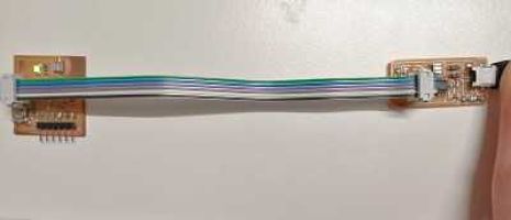
The istructor tried to programmed the helloboard with my PCB board, and it worked.
The hellowboard was succesfully programmed, as the message shows.

| LINK TO FabISP WEEKS |
In the following list there are links to each week where I used the FabISP to programm my PCBs:
- Week_6_Electronics Design
- Week_8_Embedded programming
- Week_9_Input Devices
- Week_11_Output Devices
- Week_17_Mechanical Design, Machine Design
- Final Project_Electronics
