_____ MECHANICAL DESIGN, MACHINE DESIGN _____
GOALS:
- GROUP ASSIGNMENT:
- Design a machine that includes mechanism+actuation+automation
- Build the mechanical parts and operate it manually
- Actuate and automate your machine
- INDIVIDUAL ASSIGNMENT:
Document your individual contribution to the group project
| PCB DESIGN |
For the machine building group assigment, I decided to do the Electronics part, which consisted in designing, milling and soldering the PCB.
_________________ INITIAL OVERVIEW _________________
Looking at the first, very badly attempted sketches for our machine, I noticed that, for the first time, the PCB design will had a lot of sensors (LCD display, LED, and two DC Motors.
Yes, you read well, I said the PCB design because I decided to put everything (sensors and motors) one one sigle board. Doing so, I avoided designing multiples board and adding a Communication protocol during the Programming section
I had never designed a PCB with more than two sensors, so I knew that, to avoid going crazy, I would have to keep my workflow very organised. But still, the question was: With a board with multiple sensors and motors, where do I need to start?
. Thankfully, with the help of online guides, articles and my instructor Simone Guercio, I have gathered some useful tips that helped me along the Design:
- Prior to the Design, always write down a list of the sensors and motors that you want to include on the board. In my case they were:
- Ultrasonic/Sonar sensor
- LED x 2 (Green and Red)
- LCD Display
- DC Motor x 2
- Write down how many pins you are going to need for each sensors/motors. This step is foundamental for choosing the correct Microcontroller on your board. If you skeep this step and chose a random Microcontroller, half thorugh the Design, you could ended up without enough pins.
For my PCB, I calculated at least 10 pins just for the sensors and the motors, so I decided to use an ATmega328 Microcontroller.
- Spending time reading the Microcontroller Datasheet and studying its pins functions it is a crucial step. In my case, I downloaded both the original Microcontroller datasheet as well as an intuitive and colorful diagram of the ATmega328 pins output.
______ KEEPING THE SCHEMATIC ORGANIZED AND CLEAN ______
With the increasing complexity of the PCB Design, I realised the importance of a clean and organized schematic. So, instead of having those labyrith of crossed nets, I started using the Labels tool ( Here there is very in deep-focus article about Using Eagle Schematic that helped me a lot).
To do so, I decided to use the following workflow:
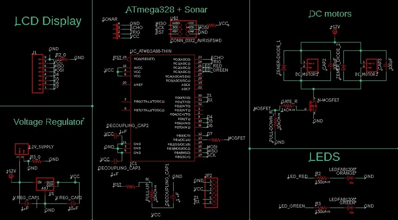
- First I did the basic microcontroller circuit. So I connected the Microcontroller with the AVRISP and FTDI connector and I made sure to connect all the VCC pins together (also AVCC) and all the GROUND pins also. Always remember to put a decoupling capacitor for each pair of VCC and GROUND ( I put three decoupling 1uF cap),
- Then I did the circuit for each sensor and the motor separately, also separating each sensor's circuit into little cells. It was the first time I use the DC motors. I decided to use the n mosfet instead of the motor driver because I didn't need to control the direction of the motors; I just needed the two of them to turn on at the same time (that is why I use one single mosfet, and one microcontroller pin -9-).
As a last step I did the Voltage regulator circuit. This was the completed schematic:
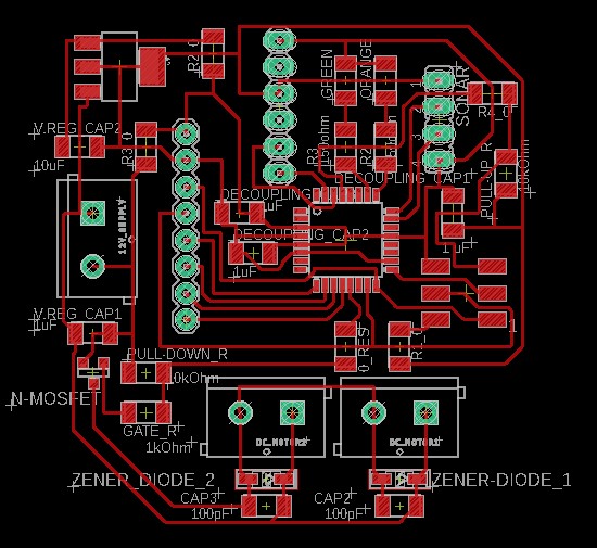
Then I proceeded routing the board.
______ CLEARANCE PROBLEMS ______
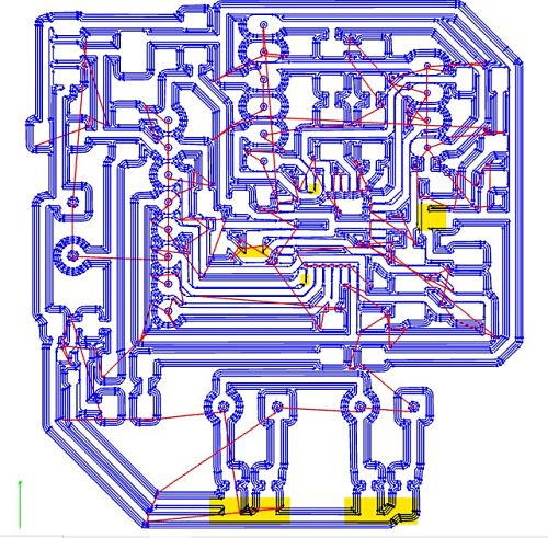
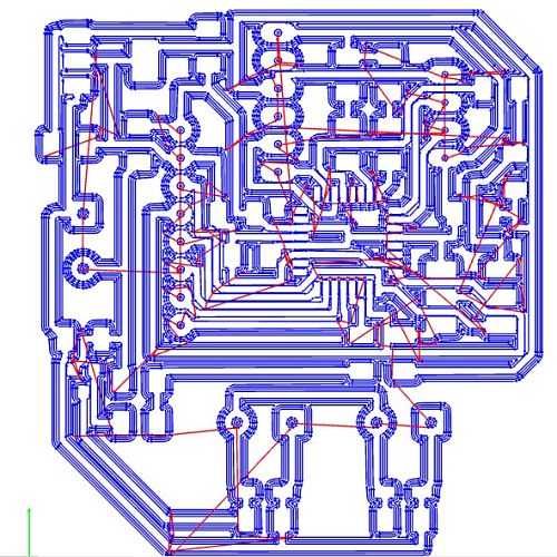
In my first routing attempt I had many clearance problem on MODS, with uncutted traces as you can see in the milling preview down below
So I unrouted the problematic traces and route them again with more distance between them.
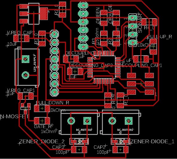
This time the preview was much better and after a first check I didn't find uncutted traces (or this is what I believed...).
| MILLING & SOLDERING |
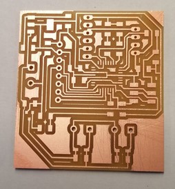
This was the milled board:
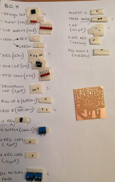
Then I proceeded gathering all the components for the Bill of Materials:
This was the stuffed board:
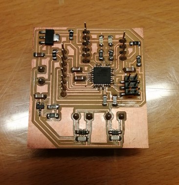
Once it was time for programming the board, the infimous RC-1 error appeared. After checking if it was the programmer or even the USB cable fault ( and it wasn't, as expected), I started checking the routes with a multimeter and I also spend time analysing if some traces were left uncutted and there was one. The MOSI trace and one pad of the 0 resistor bridge had remained attached to eachother.
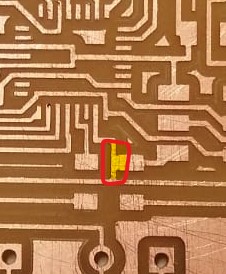
After having devided them with a cutting tool, the board was programmmed successfully with the code that my group mate Olivia wrote.
| CODE TESTS |
Here there is a first test:
Here there is the final code with my krimped cables and bigger LEDs:
