____________ E_L_E_C_T_R_O_N_I_C_S ____________
| LATCHING SOLENOID |
Since my final project will have two actuators: 3 vibration motors and 3 solenoids, and I have already experimented with the vibration motor during the output devices week. I decided to experiment also with the latching solenoid.
I used Arduino as my microcontroller, so I designed on Eagle only the motor driver cicuit.
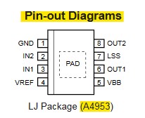
Here are the Pin-out diagram for the A4953 model:
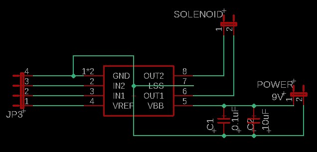
Here there are all the components that I used from the fab library and the Eagle jumper library:
- PMIC_H-BRIDGE_A4953_PAD
- 0.1uF Capacitor
- 10uF Capacitor
- JP1 = for the solenoid pad
- JP1 = for the battery pad
- JP4 = for the jumper to connect to Arduino (GND, VCC and the 2 input solenoid pins)
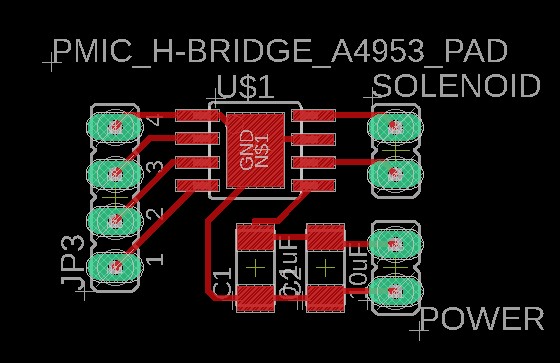
Here there is the routed board:
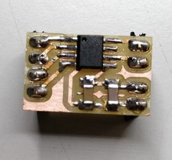
Here there is the soldered board:
Here there is the wired board:
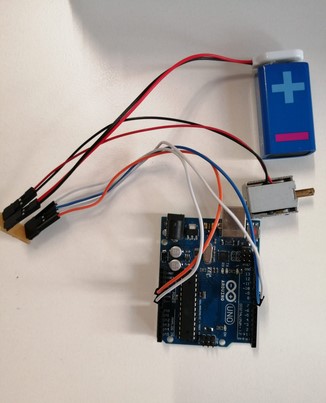
I wrote a simple code on Arduino to test the Solenoid. After plugged in the Arduino on my computer and umpload the sketch onto the board, I set 9V on the regulated power supply.
| FINAL PROJECT PCB (ESP32-Wroom-32) |
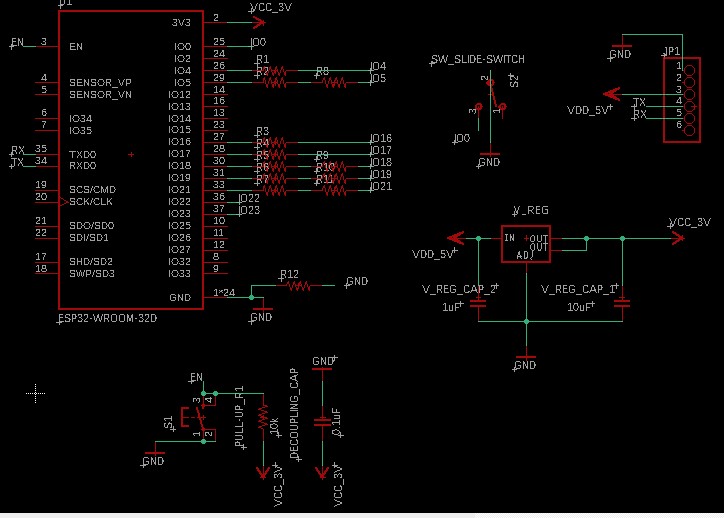
I decided use the ESP32 module fo my pcb, so I started designing the schematic adding my actuators: vibration motors and solenoids.
This is the schematic for programming ESP32-WROOM. I followed the circuit design from Niel's Networking and Communication week on the Fab Academy schedule.
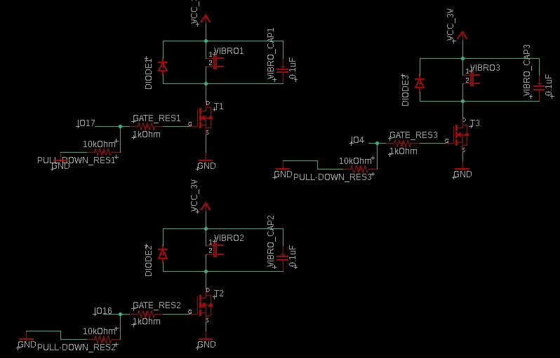
This is the schematic part for the three solenoids, that includes the motor drivers and pins for the 9V battery.

This is the schematic part for the three vibration motors ( the same circuit I did during the output devices week)
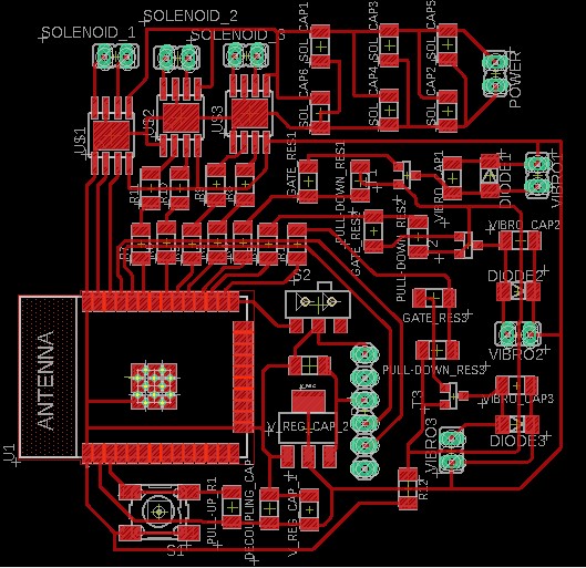
Here there is the final routed board.
You can clearly see that I used twelve 0 resistors value as bridges to reach all the ESP32 pins.
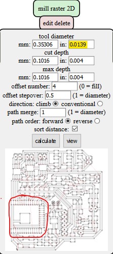
To mill the ESP32 pads, on Mods I adjusted the mill raster2D tool diameter to 0.0139.
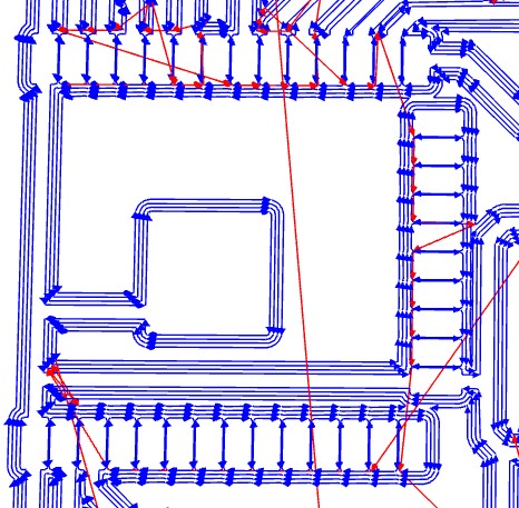
Then I procedeed with milling the board.
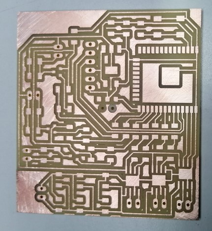
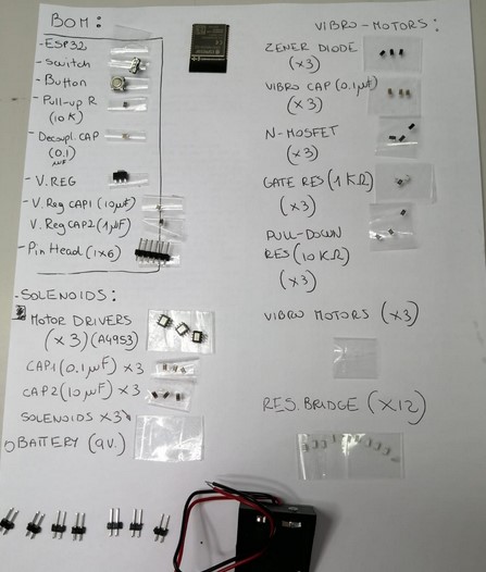
Then I gathered all the components for soldering.
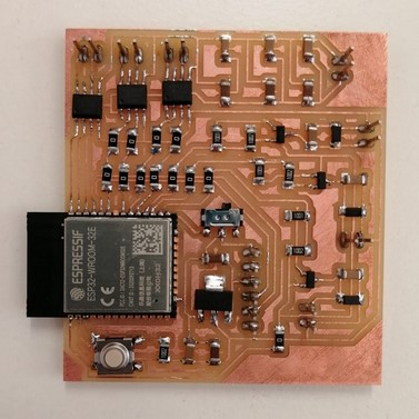
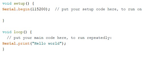
To succesfully program the board, I wrote and uploaded a simple sketch on Arduino and then checked the Serial Monitor.
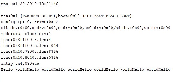
This appeared on Serial Monitor.
My ESP32 was succesfully programmed!
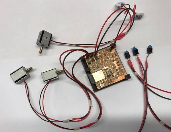
After that I wired all the motors and the battery onto the board and I began testing the final Arduino sketch.
