________________ OUTPUT DEVICES ________________
GOALS:
- GROUP ASSIGNMENT:
Measure the power consumption of an output device
- INDIVIDUAL ASSIGNMENT:
Add an output device to a microcontroller board you've designed and program it to do something
| ARDUINO GROVE KIT |
While Italy is still in lockdown, I continued my journey experimenting with other sensors and the Arduino kit.
During Week 9 I did input sensors, this week I am going to study output sensors.
In particular:
- Grove-Buzzer
- LCD Display
- Servo Motor
- Vibration Motor
________________________ BUZZER _________________________
Following the seedstudio tutorial about the Grove-Buzzer, I connected the sensor to Digital Port D6 on the Grove-Base shield. And then I connected the Arduino to the PC though a USB cable.
.
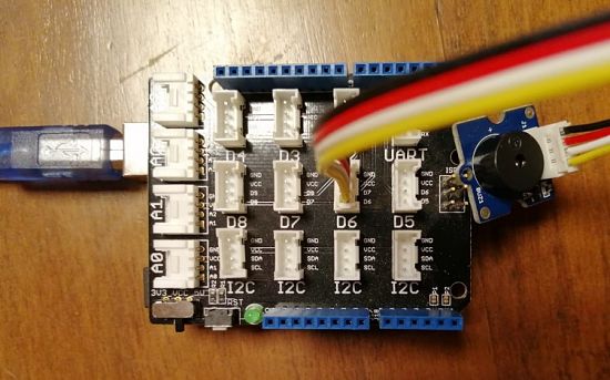
Then I copied and pasted the Buzzer Code tutorial on Arduino IDE.
I verified and upload the sketch.
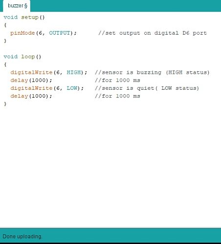
As a result, the Buzzer emitted a tone for 1s (1000 m/s) when the output was HIGH, and remained silent wen the output was LOW.
______________________ LCD DISPLAY _______________________
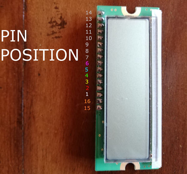
The first thing that I did was reading the datasheet of the Display, to study the Pins position and configuration.
As it can be seen from the image below, the pins position for my display was: 14, 13, 12, 11, 10, 9, 8, 7, 6, 5, 4, 3, 2, 1, 16, 15.
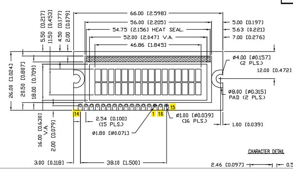
The Pin Configuration was reported in the tab below.
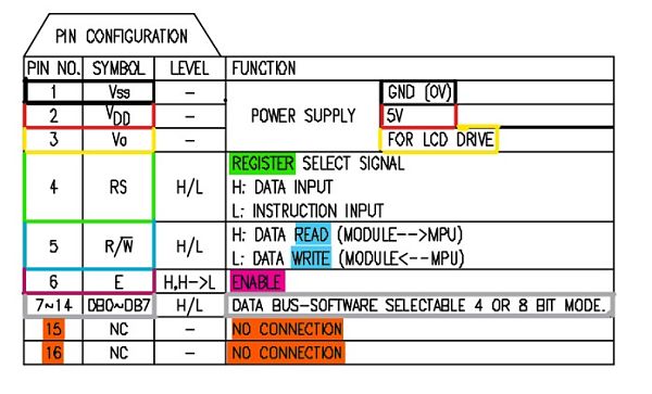
Here there is another image to help visualize the Pins position. They are highlighted with different colors for their respective configuration.
I searched a tutorial for wiring the LCD Display to Arduino, without a Potentiometer and I eventually found this one: "Arduino-Interfacing-With-LCD-Without-Potentiometer".
The wiring scheme was clear and well explained.
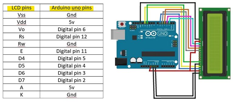
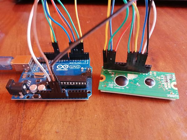
I did the wiring process, following the tutorial, except for A (Pin15) and K (Pin16), that I left unconnected. I encountered some difficulties because some jumpers were broken, but with a multimeter I managed to find the ones that didn't work.
As a last step, I connected the Arduino to my PC through the USB cable.
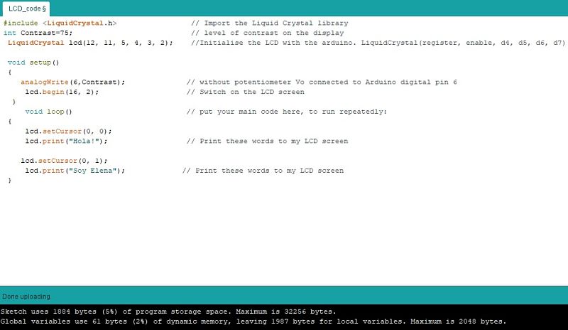
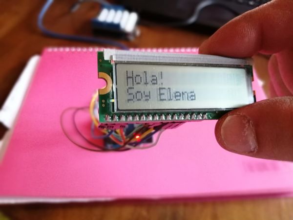
After that, I copied the code from the same tutorial on Arduino IDE, and I modified the message that was going to be wrote on the Display.
And my message appeared on the LCD display!
| THINKERCAD |
I also wanted to experiment with motors, but since the Arduino kit that the Instructor sent me didn't have one, I decided to use Thinkercad , a free, online program, that runs from browser, for 3D Design, electronics and coding.
______________________ SERVO MOTOR ________________________
The first motor I decided to use is the Servo-motor, since the instructor said that the library for the Servo is widely used and I should know it.
By the way, this guide: Arduino Servo Motors, helped me a lot understanding this type of motor.
Once I got an overview about the motor, I went on Thinkercad, I connected the servo-motor to the Arduino, and then I wrote a simple sketch to start.
___________________ VIBRATION MOTOR _____________________
As a second motor, I decided to choose a Motor that is going to play a key role in my final project: the Vibration Motor. Just to start getting familiar with it.
The understand also the difference between other types of motors I suggest this Sparkfun articles about Motors.
For wiring the Vibration Motor to the Arduino I followed this guide on "How to Build a Vibration motor Circuit".
I used:
- Arduino Uno board
- USB Connector
- Vibration Motor
- Diode
- 0.1µF Capacitor
- 1KΩ Resistor
- NPN Transistor
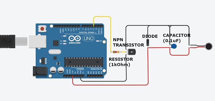
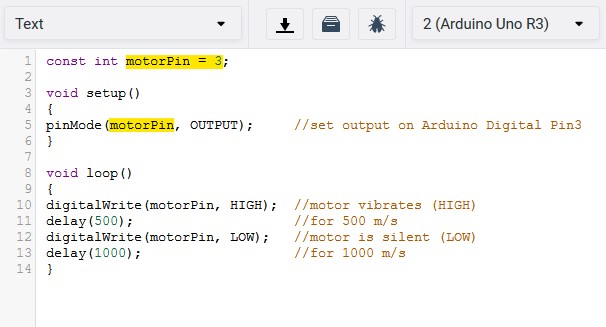
Then I wrote a simple code and run the simulation.
| PCB DESIGN |
___________________ VIBRATION MOTOR _____________________
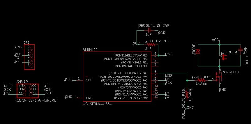
I decided to design a board with a vibration motor and ATtiny44. As for the schematic diagram and components, I followed the guide: "Circuits for vibration motors" that used N Mosfet instead of NPN Transistor.
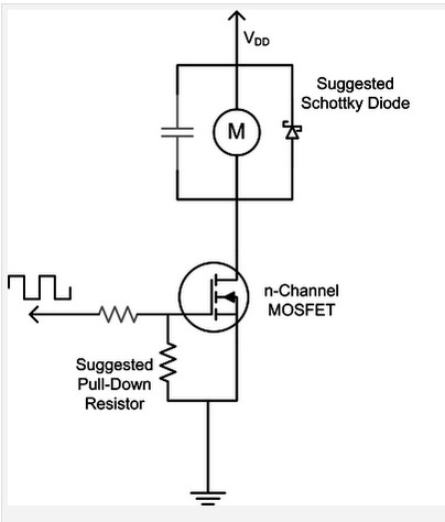
I gathered the following components for the eagle schematic:
- Microcontroller ATtiny44
- N Mosfet = used as a transistor switch
- Capacitor (0.1uF) = to reduce the high frequency electromagnetic wideband noise generated by the motor.
- Zener Diode = to protect the MOSFET against voltage spikes from the coils.
- Gate resistor (1kOhm) = useful to limit switching current from a very impedance source.
- Pull-down resistor (10kOhm) = to keep the MOSFET fully off when the active signal is not present.
- ISP Connector 3x2
- PinHead Connector 1x6
- JP1 = for the Vibration Motor. One pin connector goes to the Mosfet Drain and the other to VCC.
- Decoupling Capacitor (1uF) between VCC and GND = to abosorb eventual spikes of irregular current from a source and released that slowly.
- Pull-up resistor (10kOhm) between VCC and Reset (RST)
Always Remeber to choose a PWM pin for the Vibration motor, so after looking at the ATtiny44 pinouts, I choose to connec the motor to PA7 pin.
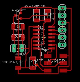
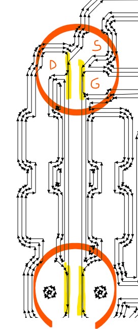
Since I wasn't sure about the trace that I did between the two motor pads, I checked it on the Mods preview and it showed that the Roland could mill the trace.
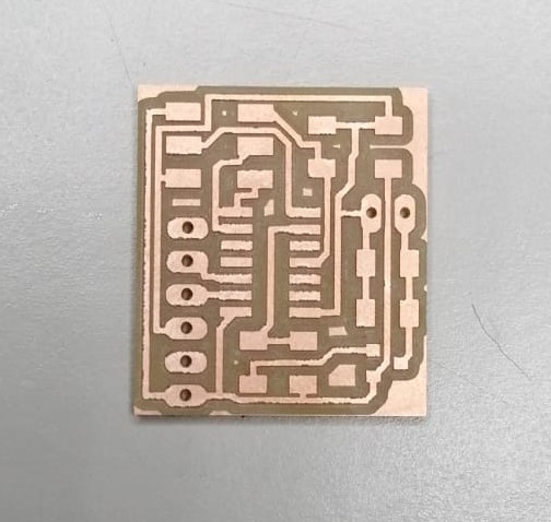
The milled board looked like this:
So I made my Bill of Materials for stuffing the board.
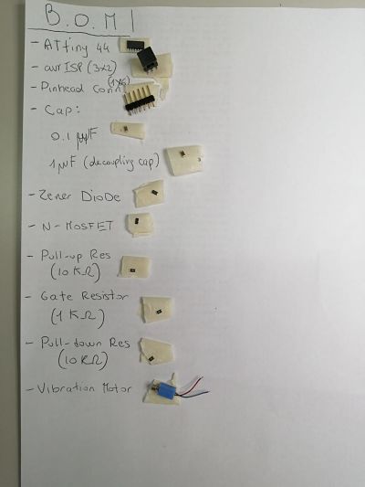
But while soldering the board, I noticed that the SCK and MISO pins were connected. It wasn't a problem with the Eagle file, but with the milling. The Roland couldn't mill those trace.
I checked the Mods preview and, in fact, it didn't mill those trace.
Next time, I know I neeed to check the Eagle preview more carefully.
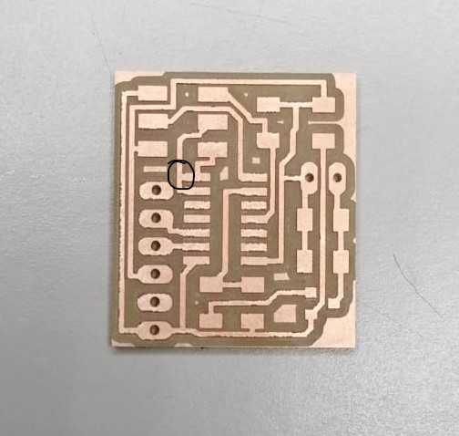
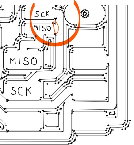
So, instead of milling another board, I cutted the trace manually with a cutter and proceced soldering.
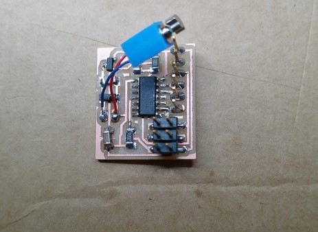
I wrote a simple code on Arduino IDE to make the motor vibrates with intervals.
And also one for the PWM.
On Arduino IDE I set the ATtiny44 Board, the programmer, internal clock. I clicked on "Burn Bootloader" and then I uploaded the sketch by clicking on "Upload with Programmer".
