__________ COMPUTER-CONTROLLED CUTTING __________
GOALS:
- GROUP ASSIGNMENT:
characterize your lasercutter's focus, power, speed, rate, kerf, and joint clearance
- INDIVIDUAL ASSIGNMENT:
- Design, lasercut, and document a parametric press-fit construction kit, which can be assembled in multiple ways. Account for the lasercutter kerf.
- cut something on the vinylcutter
| ROLAND GS-24 VYNIL CUTTER |
This week I started using the Roland GS-24 Vinyl cutter, which is a a type of computer-controlled machine
mainly used for trimming vynil (a self-adhesive plastic) into shapes.
So, as it was my first experience with the machine, I decided to cut two decorative stickers. The first one had a simple contour, the second had a more complex one.
_____________ PREPARING THE IMAGE ON INKSCAPE _____________
VECTORIZE (TRACE BITMAP)
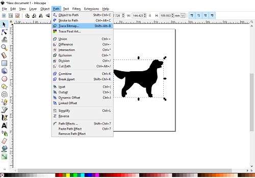
The first step after importing the image on inkscape was vectorialize the image with "trace bitmap" from the "path" section on the tools bar.
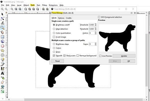
You can change the default threshold parameteres and track the changes on the images in real time with "live preview" button. Then click "ok"
RESIZE TO PAGE
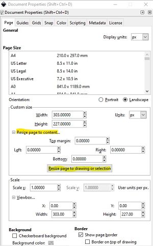
To make sure you export the whole image and not just part of it, it is important to resize your image to the page size
EXPORT
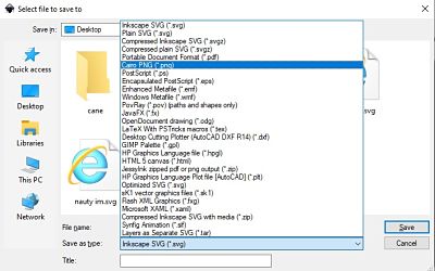
I saved my first file with the option save, but when I imported the file on Cutstudio, it didn't outline the borders of the image, so I saved with a png cairo format and that worked.
___________________ MACHINE SETTINGS ___________________
1. First of all you have know the size of the cutting and move the white tags according to it. This way the machine will know the cutting area.
2. Then open the black lever on the left and insert the piece of vynil material.
3. Close the lever.
4. Click on Select Sheet -> Piece.
5. Press the ENTER button.
6.After the machine has finished check the material. Press the ORIGIN button until it starts flashing on the display.
REMEMBER! To modify or discard the previous settings double click on MENU and then on UNSETUP.
___________________ ROLAND CUT STUDIO ___________________
After setting the Origin on the Vynil Cutter, I imported the image on Cut Studio (the programm for the ROLAND Vynil Cutter) and then I right clicked on the mouse and select "contour cutting"(remember to always check the size of the image before cutting).
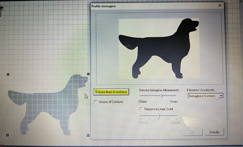
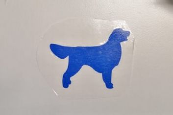
Then, after checking that the setting of the vynil cutter were correct, I press "cut" form the tool bar and this where the result of two different stickers:
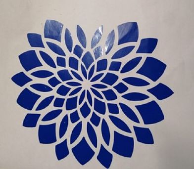
The mandala wasn't cut properly because the size of the paper was a litle bit shorter. This was the result:
| TROTEC LASER CUTTER |
__________________ PARAMETRIC 3D DESIGN __________________
My idea for the press-fit construction was a sort of jenga tower that had spaces cutted to insert other joints of different shapes going inside the tower. It was composed by two main cubes and other joints that inside the construction. In Onshape I created the sketch for the faces of my cube, inserting variables (x) for all kind of measures, including the Kerf (0.1 mm) that was found with the group assignment.
So I added the Kerf variable (which I called K) to the long side of the male joint. And I subtracted the K value from the logn side of the female joint.
I started the design with the the faces of the inferior cube.
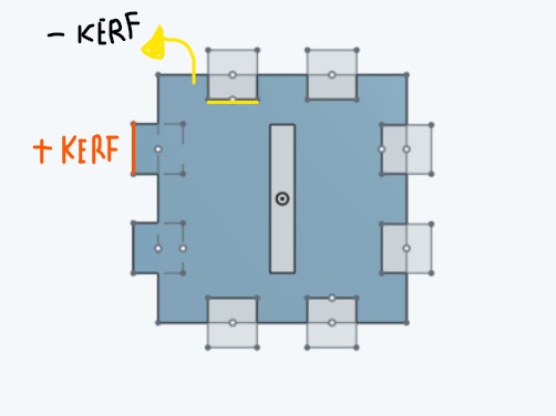
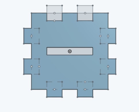
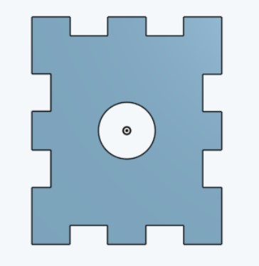
And the base of the cube.
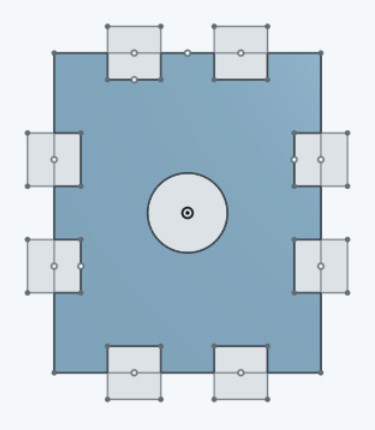
Then I proceded with the faces of the second cube.
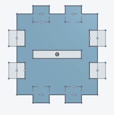
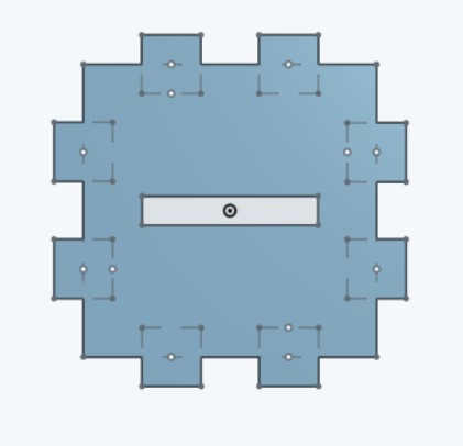
And the top of the cube.
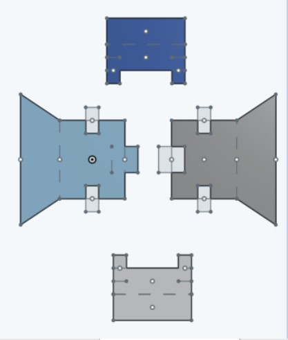
As a last step, I designed the internal joints.
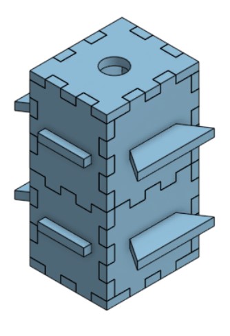
On the "Assembly" window, I inserted the two cubes one on top of the other and then I connected them with "mate-connector", inside of the tower.
__________________ ADOBE ILLUSTRATOR __________________
After exporting all the pieces in the DXF format from Onshape, I imported them on Adobe Illustrator by clicking on File -> Open .
Then I checked that the shape was completely merged by selecting the object and clicking on CTRL + J . If you have another shape inside of your object that you want to merge separately, firstly merge the internal shape, then select all the shapes (internal+ external). After that, while pressing SHIFT select again the internal shape to deselect it. Once only the external shape is highlighted, merge it with CTRL + J.
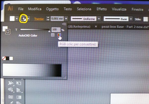
I selected the object and change the traces size to 0,001 mm . After that I clicked on the icon with the double black square while pressing SHIFT to open the RGB panel and change the parameters according to the color that you have assigned to the cut on the JobControl software. In my case, the playwood cutting with 85 Power and 1 Speed, was assigned to red.
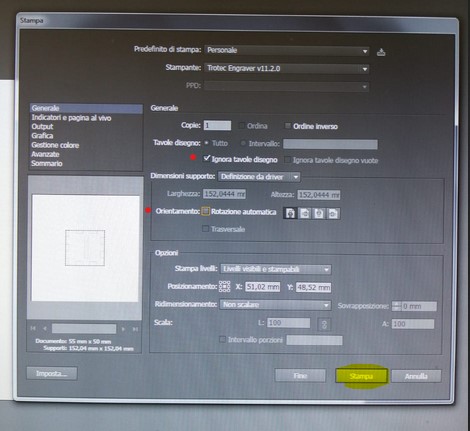
Then, I clicked on File -> Print , opening the first print window menu. I pinned Ignore Artboard , disabled the Automatic Rotation option and then I clicked on the left corner button:SETTINGS.
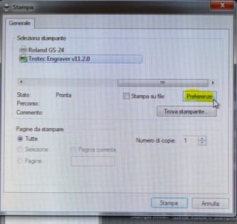
A second print menu opened up for the printer selection. I clicked on Preferences.
The Preferences menu opened up.
First of all, I added 2 cm to both width and height, I checked the material settings, the work settings including the resolution and I pinned the "optimized geometry" and the "internal geometry first" options.
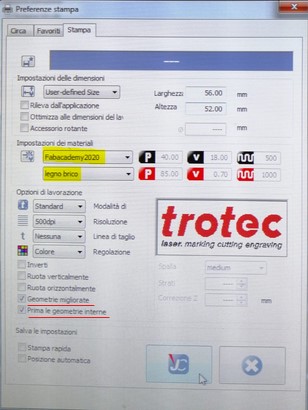
Then I clicked on the JobControl icon and returned to the first print menu, clicked again on "Settings -> Print", then returned to the first menu and finally clicked on "PRINT".
After a couple of seconds the JobControl Icons appeared as a minimized windows on the bottom menu of the Computer.
_______________________ JOBCONTROL _______________________
After clicking on the blinking JobControl icon. I selected my file on the right corner with a double click.
My file appeared on the screen as a black square, I clicked on it and then press CTRL + I to have a visual preview of the file.
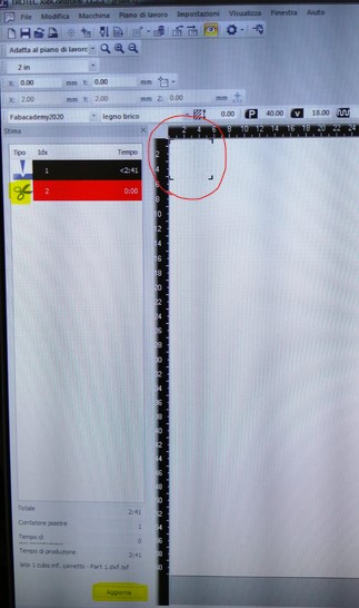
On the left part of the screen, there were informations about the the type of cutting ( if its a plain cutting -red- or an engraving - black-) and also the estimated worktime.
Once I checked that the cutting I wanted was associated with the red color, I clicked on "UPDATE" to upload the new settings.
The file was now ready to be laser cutted!
_______________ PRESS-FIT CONSTRUCTION KIT ________________
Once the previous steps were all completed, I started the cutting process on the Trotec laser cutter using a plywood sheet (with 5 mm of thickness) as a material.
I cutted the Cubes faces and the different joints that went inside the tower.
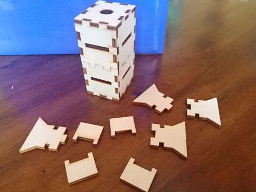
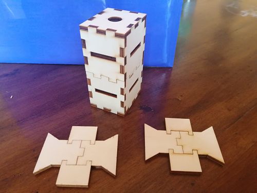
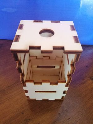
Here there is the inside of the tower without the internal joints:
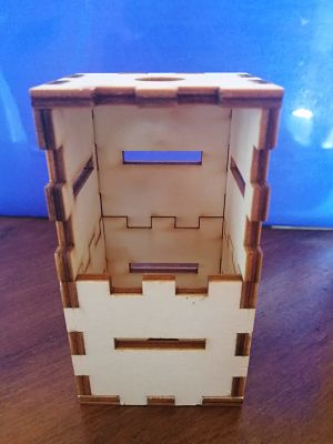
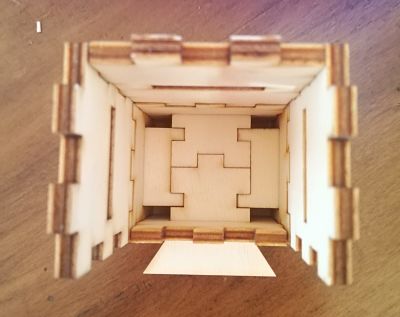
Here there is the inside of the tower with the internal joints:
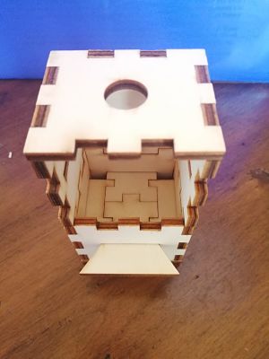
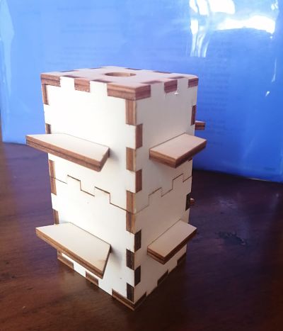
Finally, this was the final result:
