__________ NETWORKING AND COMMUNICATION __________
GOALS:
- GROUP ASSIGNMENT:
Send a message between two projects
- INDIVIDUAL ASSIGNMENT:
design, build, and connect wired or wireless node(s) with network or bus addresses
It is May the 5th and I still can't have access to the Lab, so this week I decided to experiment with the two Arduinos inside my kit and the Wired Protocols:
In the following paragraphs you will see me exploring the asynchronous Serial Communication, and synchronous communication I2C (Inter-Integrated Circuit).
| SERIAL COMMUNICATION |
Serial interfaces stream their data, one single bit at a time.
The data/bits are sending in "serial", so this makes the communication process much slower.
There are are types of synchronous Serial communication (with Clock reference) ad asynchronous (without Clock reference) types too.
For the asynchronous Serial Communication, I followed an oline article about Serial Communication Between Two Arduino Boards . I decided to make the Master board send a simple message to the Slave board, that I could check through the Slave Serial Monitor.
MASTER SKETCH
SLAVE SKETCH
Then I plugged in the Master and Slave Arduino Boards (one at a time because I have just one USB cable) and I uploaded their respective sketch.
For connecting the two boards I used GND and VCC/5V pins (I did this to power the second board, since, again, I have just one USB cable) and I also connected TX -> RX pin, and RX -> TX pin between the two boards.
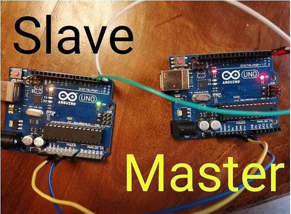
This was the message that appeared on the Slave Serial Monitor:
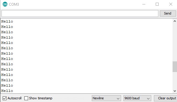
| I2C (INTER-INTEGRATED CIRCUIT) |
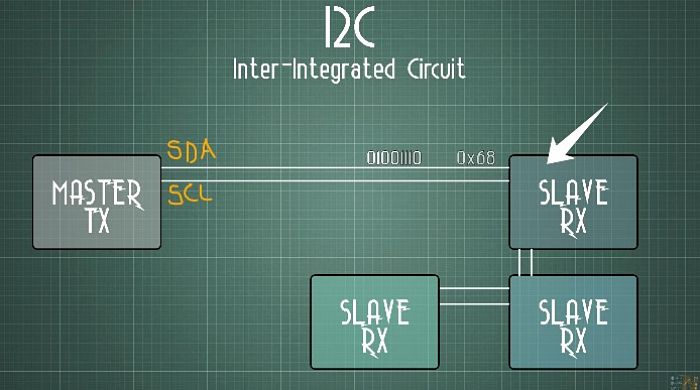
It is a synchronous communication. It needs two connections, plus the ground reference. One wire will send the DAta (SDA), the second wire is the CLock (SCL), because this is a synchronous communication.
We need to specify the amount of bits that we send and also the clock frequency for both the transmitter(MASTER-TX) and the receiver(SLAVE-RX). Usually 12C works with speed up to 400 Kilobits/s and it will send data of 15/16 bits.
At the same time we send the data (through SDA line), we also create a clock post ( though SCL line) with the same frequency of the bits of the data, so we can know when each bit starts and ends.
Using I2C, the transmitter will send any type of data, but only certain receiver will be able to store the values. This is done thanks to the "SLAVE address".
Each receiver will have a different "SLAVE address" (SLAVE RX). The transmitter will send the "address ..." and then it will send the data. The data will be store only in the buffer of the receiver that matched the address "...".
The I2C communication is a 1 to 1 communication, but it can be used with multiple receivers (each one with a different address).
For the week assignment, I researched different kind of projects involving the I2C Communication and inspired by online guide about I2C communication at dronebotworkshop.com, I decided to connect a potentiometer on the Arduino Master, to control the LED blinking speed on the Arduino Slave.
First of all, I started to getting familiar with the Arduino Wire Libraryand all its functions.
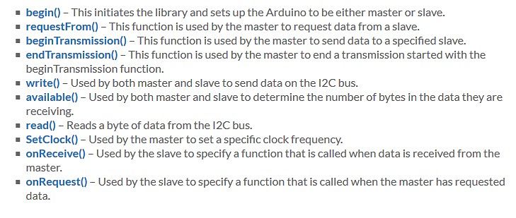
Then I wrote the code for the Arduino master.
MASTER SKETCH
Then the code for the Arduino Slave.
SLAVE SKETCH
For the wiring process, I connected the grove-potentiometer on pin A0 of the Arduino Grove Base shield ( my Master Board), and then on the Slave Board I used the LED already built-in on pin 13.
Since I don't have two USB cable I plugged-in the two Arduino separately on the PC USB port.
To be more specific, I plugged-in the Arduino Master and I uploaded the Master Sketch. After that, I plugged-in the Arduino Slave and uploaded the Slave sketch.
Having the Master and Slave sketches ready to go, it was time to connect the two Arduinos.
So, I connected the VCC (5V) and Ground pins, and also the SDA (pin A4) and SCK (pin A5).
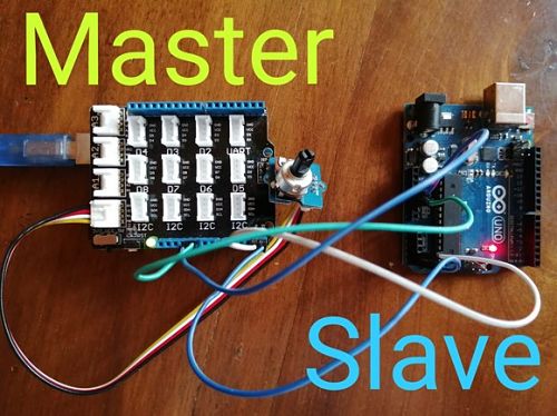
Then I plugged-in the Slave Arduino and I opened the Serial monitor on the Slave Sketch to see the data sent by the Arduino Master.
This was the final result:
