____________ CONCEPT & 3D CAD DESIGN ____________
| INTRODUCTION: EUREKA |
Modern design studies have tried to improve accessibility to museums for the blind and visually impaired people by using Tactile Maps: maps that reproduce the museum on a planimetric scale, with raised line and braille markers that can be touched.
I researched about tactile maps and found interesting articles describing different designing projects of "tactile maps" like Lighthouse or Acuity,
and even Interactive audio-tactile maps for visually impaired people, but few of them combined tactile maps and more interactive feedbacks.
For my final project, I decided to step up the game and implementing a vibration feedback to the tactile map.
This will allow an easier and much faster position recognition compared to a simple tactile scanning with your hands..
I also sum up all the weeks that this final project will involve:
- 2D Design: for the tactile map.
- 3D Design: for the tactile map and the packaging box.
- Machine-controlled cutting: for creating the map using the laser cutter
- 3D Printing: for supporting the PCB, the solenoids and vibration motors.
- Electronics Design and Production: for the Solenoids and Vibration Motors outputs
- Embedded programming: for the Solenoids, Vibration Motors, Bluetooth modules (Beacons), and to wrote the BLE Scanner sketch code (Using ESP32 BLE LIbrary for Arduino IDE)
- Input devices: Bluetooth - Beacons signals.
- Output device: Solenoids and Vibration Motors.
- Networking & Communication: because the devices (PCB and Beacons will communicate with each other).
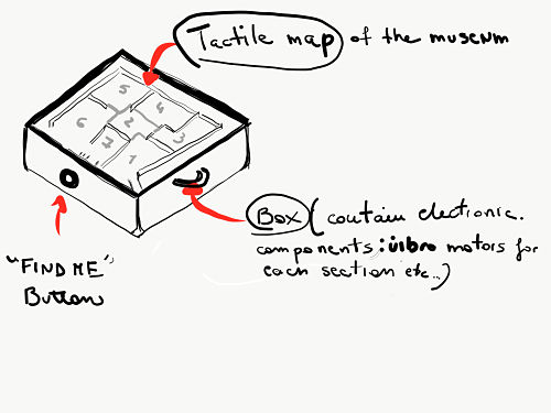
| 3D DESIGN |
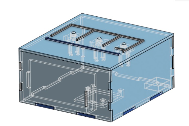
The device that I am envisioning has the structure of a box, in a portable size that is comfortable to carry inside a building.
On the top of the packaging box there is the tactile map ( for this project I decided using 3 rooms). Under the map, I'm thinking of putting the solenoids structure:

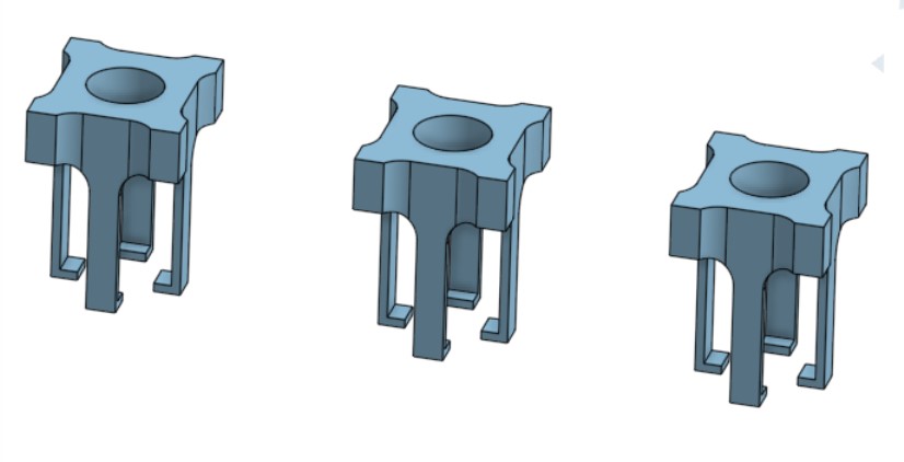

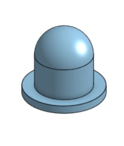
Inside the box there are all the electronics components (like programmable computer boards, vibration motors, etc...). I created also a pocket for the powerbank:
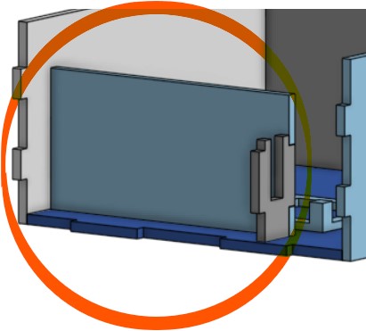
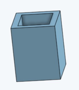
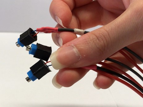
A pocket for the vibration motors:
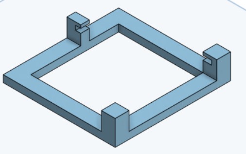
And a structure for holding the PCB:
As for the material of the tactile map, previous articles that I mentioned used steel because of its low maintenance but I think it is too heavy for my project. The best alternative would be resin, although required a high budget and a slower making process. Given that fact, I think that the best option for a first prototype will be playwood for the map and wood for the packaging.
| ASSEMBLY |
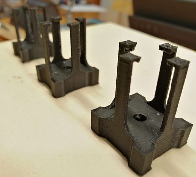
I started by 3D printing the solenoid_holders:
Then the pins:
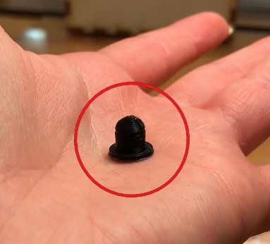
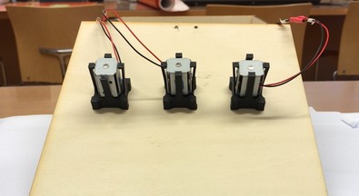
The vibration motors pockets:
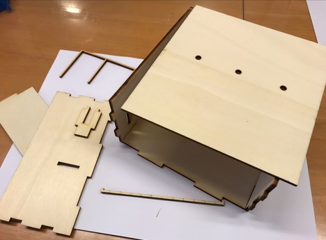
Then I laser cutted the plywood pieces:
This was the board structure:
This was how all the components were organised inside the map.
This was the final result:
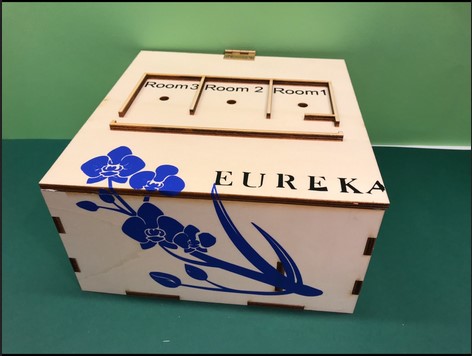
| BLE (BLUETOOTH LOW ENERGY) COMMUNICATION |
The tactile map will need bluetooth modules. I am thinking about HM-10 Beacons , with pro and cons of the case, especially limits like maximum distance and possible signal obstacles. I researched the possible uses of beacons and development kits on estimote).
Each sensors will be installed and paired with a section/room of the museum.
The map will automatically detect the nearest Beacon (thanks to its Address and RSSI).
As a direct consequence, the area of the map with which the sensor was previously paired will emit a slight vibration.
For example, if the User is in room 1, the map will detect the nearest Beacon, which in this case is Beacon1 in room1. As a result, Fistly: the Vibration motor connected to room 1 on the tactile map will vibrate. Secondly: the Solenoid under room 1 will come up.
For the blind User, this method will allow an easier and much faster position recognition, rather then a tactile scanning with the hands.