GROUP ASSIGNMENT
- test the design rules for your 3D printer(s)
STUDENTS
Olivia De Masi, Chiara Diana, Elena Racanicchi
We tested the following settings:
1. Layer height.
2 Wall thickness
4. Speed and sharpness corner.
5. Overhang.
6. Bridge.
7. Final Ctrl-V test
1. LAYER HEIGHT
1.1 THINGIVERSE
We downloaded the STL file from Thingiverse, an opensource website created for sharing user-created digital design files.
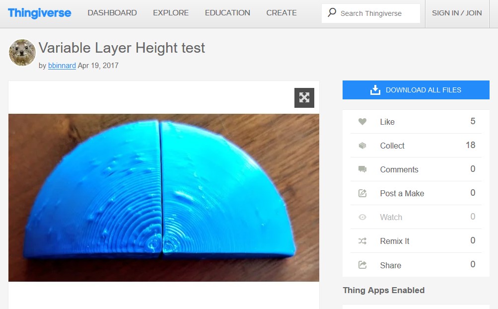
We clicked on "thing file" to directely download the STL file.

Then we imported the STL file into Meshmixer, a free 3D modeling software, to check that the figure was completely sealed.
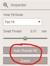
From the tools menu on the left, we clicked on "Analysis" and then on "Inspector".
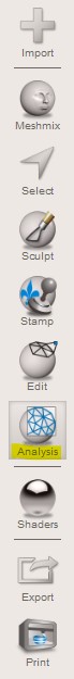
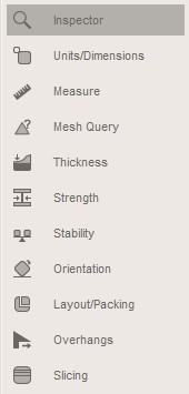
If the figure appears grey without any red signs, it means that the shape is completely sealed (for further validation we clicked on "Auto Repair" and "Done").
Ultimately, we saved the file in STL.
1.3 ULTIMAKER CURA 4.5
Since our Lab has a 3D printer Ultimaker 2+, we installed the recommended free slicer software Cura to convert the 3D models into 3D print files.
After having imported the STL file, we had a preview of the object we wanted to print.
On the small menu on the left of the screen, click on "scale" you can set the axes measures:

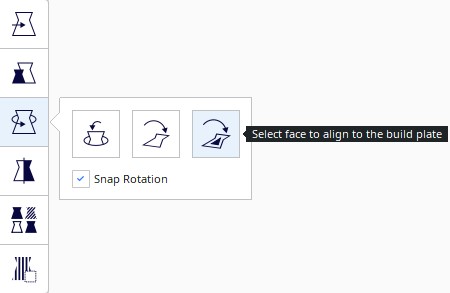
The click on "rotate -> lay flat" to make sure the object touches the plate properly.
On the top right side, click on the pencil icon to open up the setting menu.

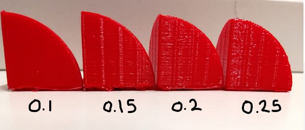
Starting form the layer height setting, we decided to test the following ranges: 0.1, 0.15, 0.2, 0.25, and leaving all the other settings with the default parameters, except for:
Shell - Z seam Alignment: with this setting, you can choose where each new layer in the Z direction starts.
The default parameter is set on the "sharpest corner", this means that the next layer of filaments starts form the sharpest inward or outward corner of the model.
This increases the visibility of the seam but decreases the print time.
Following our instructor's advice, we changed the parameter to "random" so that the next layer starts at a random point of the previous layer.
With this modality, you will not have a continuous seam, but print time will increase due to travel moves.

The results of the test suggested that the best parameter is 0.1 (although it requires a lot of time and it is not necessary if you do not have to print a detailed object.) , the layers were perfectly defined and the surface of the material was smooth and translucent, without evident filaments cloggings.
2. Wall thickness
The definition taken from the official site of Ultimaker Cura describes it as "the setting adjusts the thickness of the walls of the model.
A higher value decreases the chance of leaks, while a lower value can significantly decrease the print time and filament costs."
For the wall thickness test, we printed a simple cube with three different thickness settings (0.4, 0.8, 0.12 ).
In fact, the parameters must always be a multiple of the extruder (in our case 0.4).
k We kept unchanged the infill parametre (20%) and the speed (100 mm/s).
It turned out that the best setting has been 1.2. From the picture below, you can notice that the surface is much smoother.

3. Speed and sharpness corner
"The print speed defines the speed (in mm/s) at which the print head moves while printing.
Based on this setting, Ultimaker Cura calculates the extrusion flow.
The print speed can be visualized per feature in the Layer view > Feed rate. Higher print speed will lead to shorter print time.
Keep in mind that increasing the print speed means that you may have to increase the temperature as well to ensure the filament is properly melted."
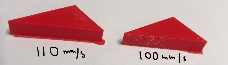
To calculate the angle sharpness, we drew a dull-angle triangle with different angles degrees on Onshape, and then we 3D printed it twice, the first time with the speed set on 100 mm/s, and the second time with 110 mm/s.
We thought 100 mm/s velocity was too high, but the result was pretty good even with 110 speed: at this speed, the angle is defined and the printing process is faster.
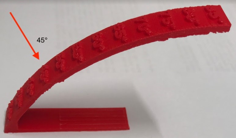
4. Overhang.
"The overhang angle influences how much support material is added. A smaller angle leads to more support. For example, at a value of 0°, all overhangs are supported, while at 90° no support material is added."
We tested the overhang on a scale from 30 degrees to 85 degrees not using a support.
It turned out that the minimum angle that we can print is 45 degrees, 45 to 55 degrees can be considered almost acceptable, but beyond that it is impractical.
5. Bridge
It is the connection that the printer can make without a media, i.e., in the air.
We tested the bridge using 4 different speeds: 90 mm/s, 100 mm/s, 110 mm/s, and 120 mm/s. And the folliwing other settings:
- Layer height: 0.2
- Wall thickness: 1.2
It turned out that the test eithh 120 mm/s had the best result.
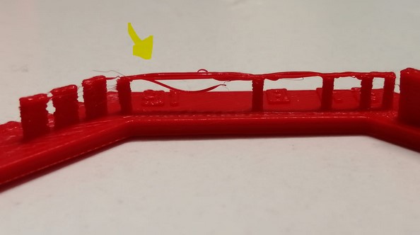
With the previous, tested parameters, the filaments that recreate the bridge didn't stay in place to form a homogeneous, compacted structure for the bridge, as it can be seen from the image below.

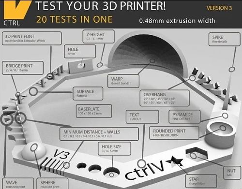
5. Ctrl-V test
At the end, we decided to do a final test, incorporating different shapes in one construction.We downoladed the ctrl-V test from Thingiverse.
We tested it two different speed: 120 mm/s and 100 mm/s while keeping the following setting, uchanged:
- Layer height: 0.2
- Wall thickness: 1.2
- Infill: 17%
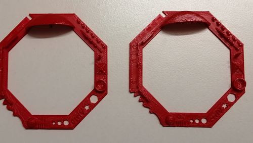
Both tests had a similar outcome. They didn't encounter major issues with speed 120 mm/s and 100 mm/s for creating the shapes (sphere, piramid, even the holes were clean), but the bridges, and especially the agles had some filaments going out from the original shape, which led our istructur to suggest to try, next time, a speed of 80 mm/s.