MACHINE-CONTROLLED CUTTING
1. SHOPBOT
1.1 SAFETY
We started with saftey rules wright away. Our lab provided us with:
- glasses
- protective suit
- earflats
- gloves
- face mask
We always kept our hair tied and in the hood and we always took of any jewellery. We learnt to always be at least 2 people
and to keep a saftey distance while the shopbot is working for additional safety reasons.
1.2 Machine settings
This is the axes's knob:
This is the key to turn on the head spindle:
This is the vacuum and the dust collector
1.2.1 Endmill insertion procedure
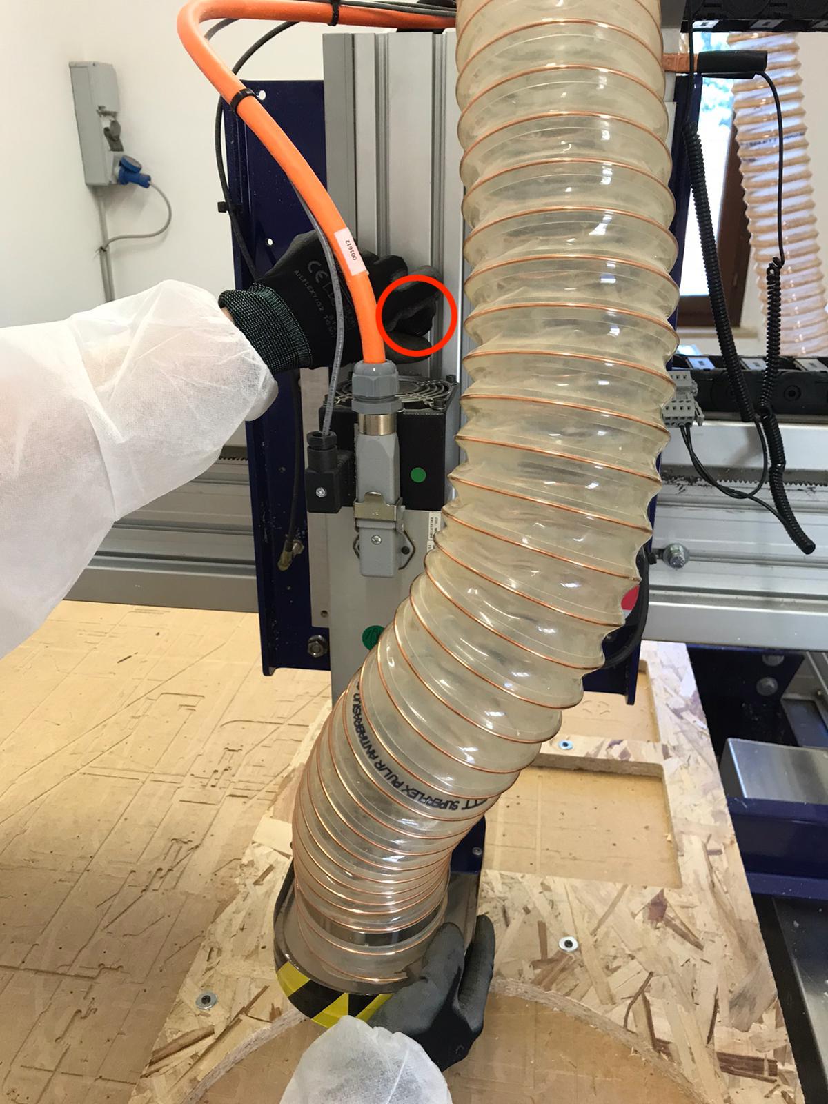
1)Removal of the vacuum block: turn the knob clockwise while holding the vacuum block utill it's loosen.
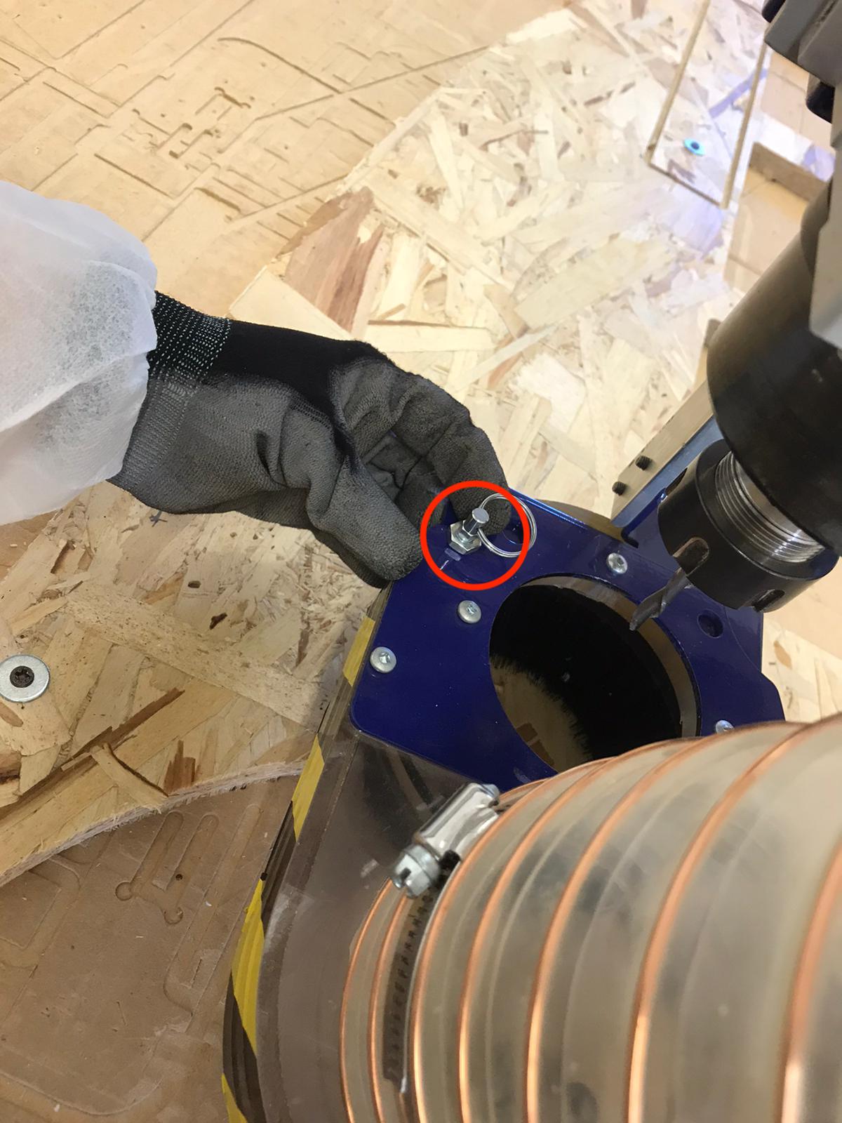
Unscrew this bolt to completely remove it from the head spindle:
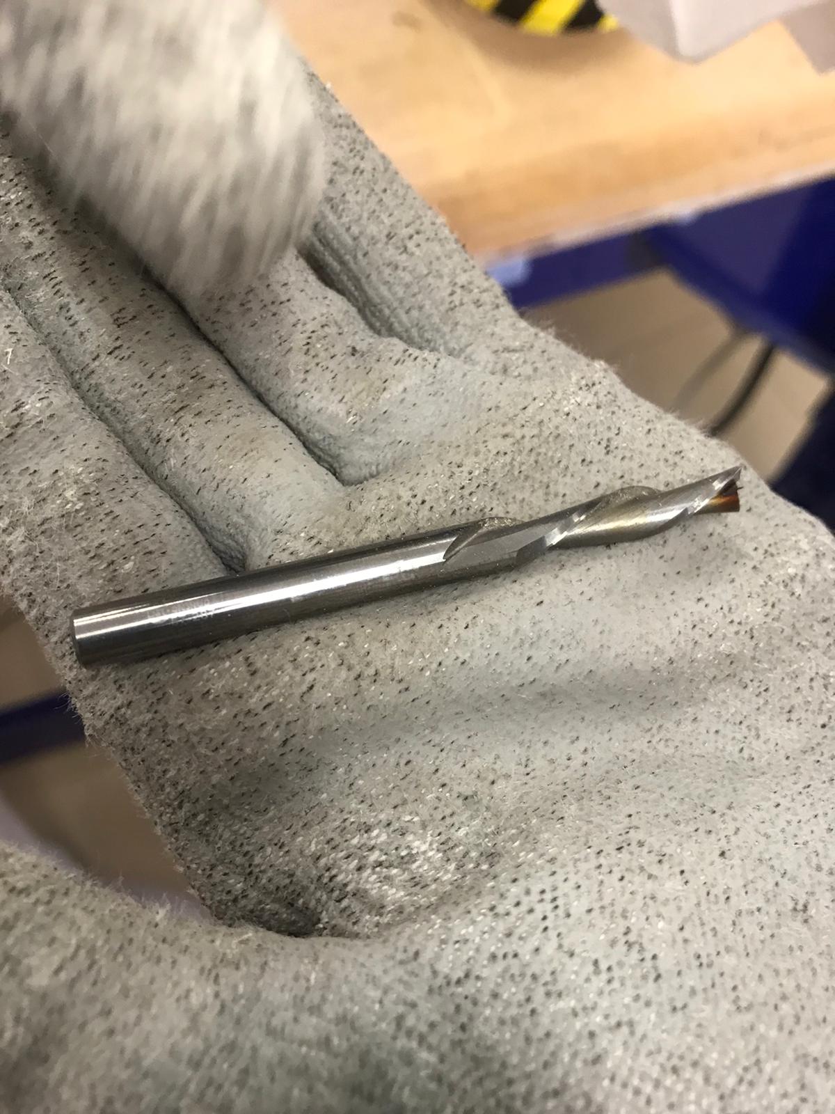
2) Endmill features:
- flat
- diameter 1/4 inch
- 2 flutes
- downcut
3) Endmill insertion: after inserting the endmill in the head spindle while one person should hold onto it while
the other person uses these two special wrenches:
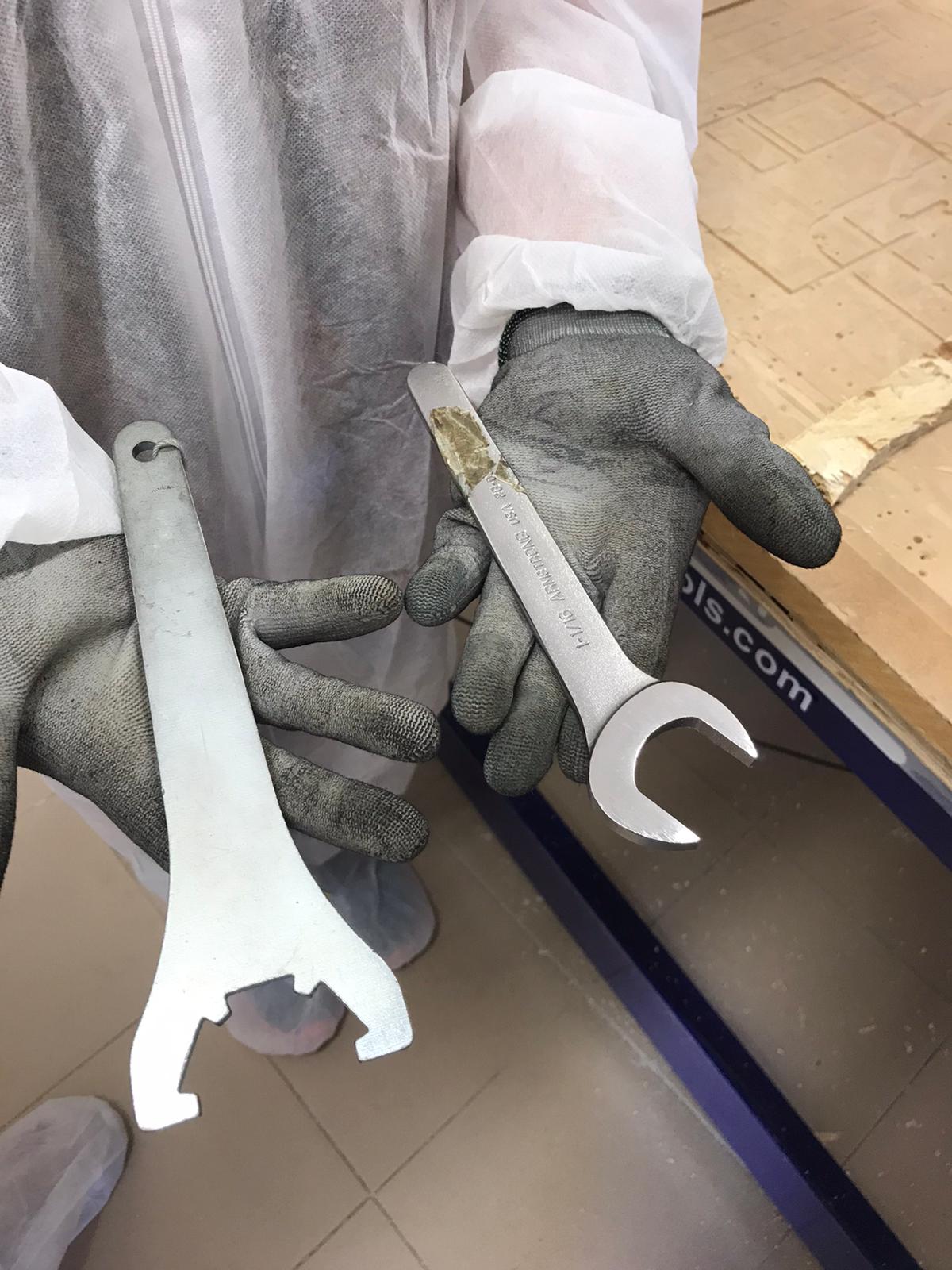
N.B. During the Endmill insertion procedure, the head spindle MUST be turned off.
As a reminder of this, our Lab attached one of the special wrench to the key that turn on the Head Splindle.
A a consequence, to use the special wrench you need to extract the key, but you can extract it only if the head spinde is turned off.
To tighten the head spindle and secure the endmill push the two wrenches away from each other (while to loosen it pull them towards each other):
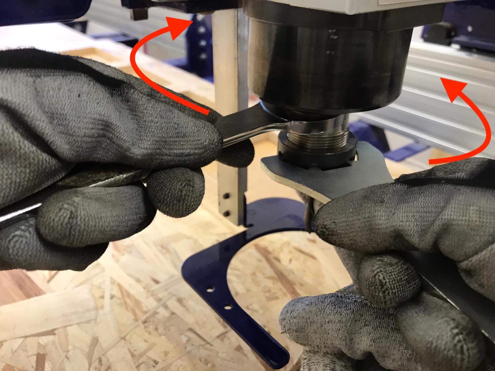
N.B. Be careful to insert the endmill around 1 cm away from the flutes.
4) Reposition the vacuum block following the reverse procedure
Positioning of the OSB board
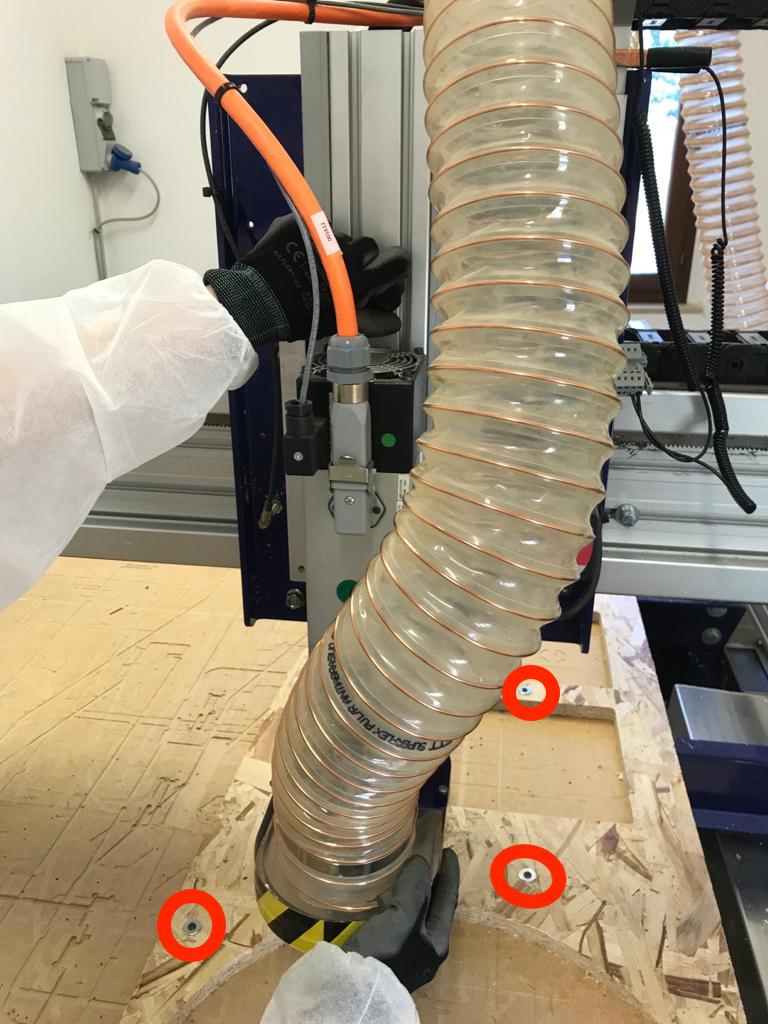
After moving the head spindle away from the work space desired on the machine to avoid collision, put the wooden board on the sacrificial layer and secure it using screws and washers (to balance the pressure of the screws). Advise: to smoothen the insertion use some hand soap. This procedure is to secure the board and also to avoid boardening of the wood.
Software settings
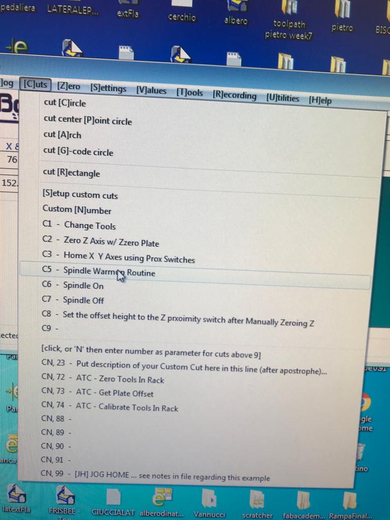
Once the machine settings we're done we turned the key to start the engine of the spindle and we moved to the computer station to
start the worm up procedure:
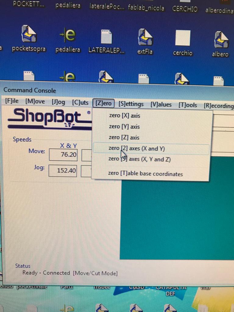
After approximately 15 minutes of worm up we set the x and the y in the work space we
wanted to cut:
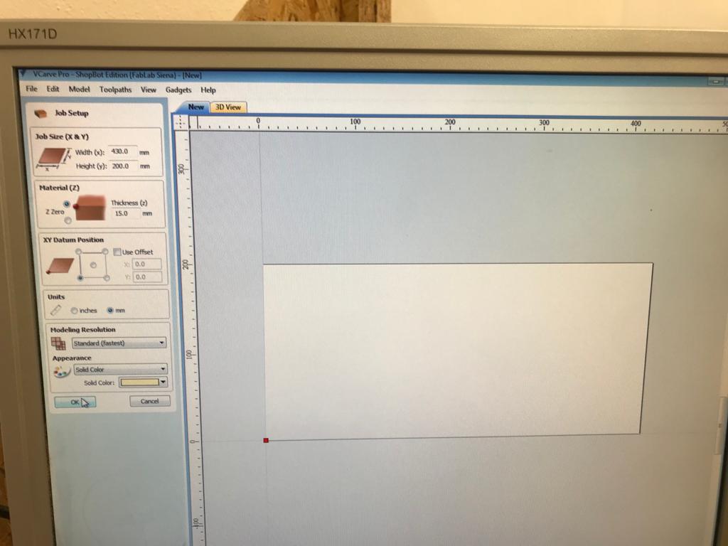
So we opened the g-code software VCarve. As a first thing we set the work surface (thickness, hight and width of the material), when the previw shows up on the screen we checked that is was like the one we had on the machine.
FEED RATE TEST
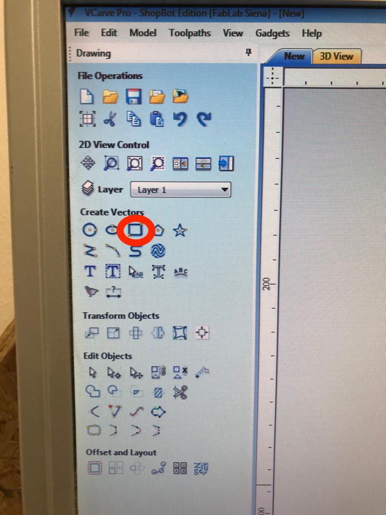
For this test we drew 3 squares (12cm x 12cm)
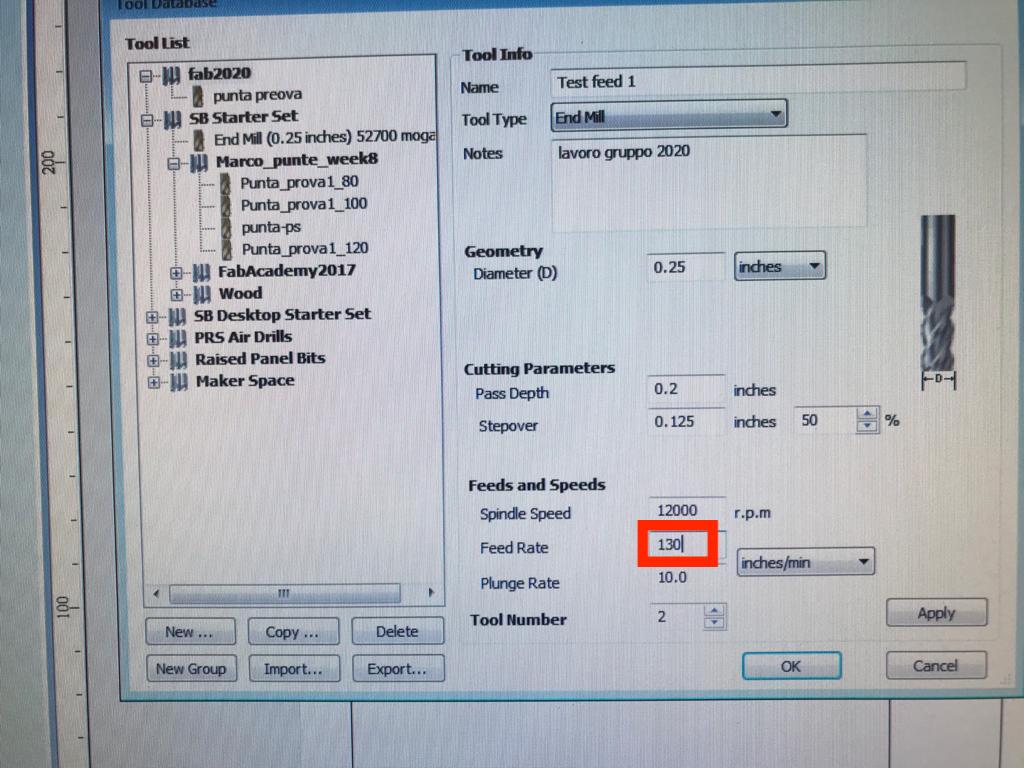
We then created 3 different files for the settings of the endmill to test the feed rate from the upper "tool - tool database" menu. We decided to test 130 / 105 / 80 inches per minute:
Parameters
1. Tooltype: is type of cutting tool, we selected endmill.
2. Diameter: it's the diameter of the endmill, ours it's 1/4 inch.
3. Pass depth: it's how deeply the endmill cuts in one pass.
4. Step over: the inches the endmill moves on the x and y axes.
5. Spindle speed: it's the endmill rotation speed.
6. Feed rate: it's the speed of the cut (inches per minute).
7. Plunge rate: it's the speed of the endmill on the z axis.
8. Tool number: it's the number of the flutes.
Toolpath
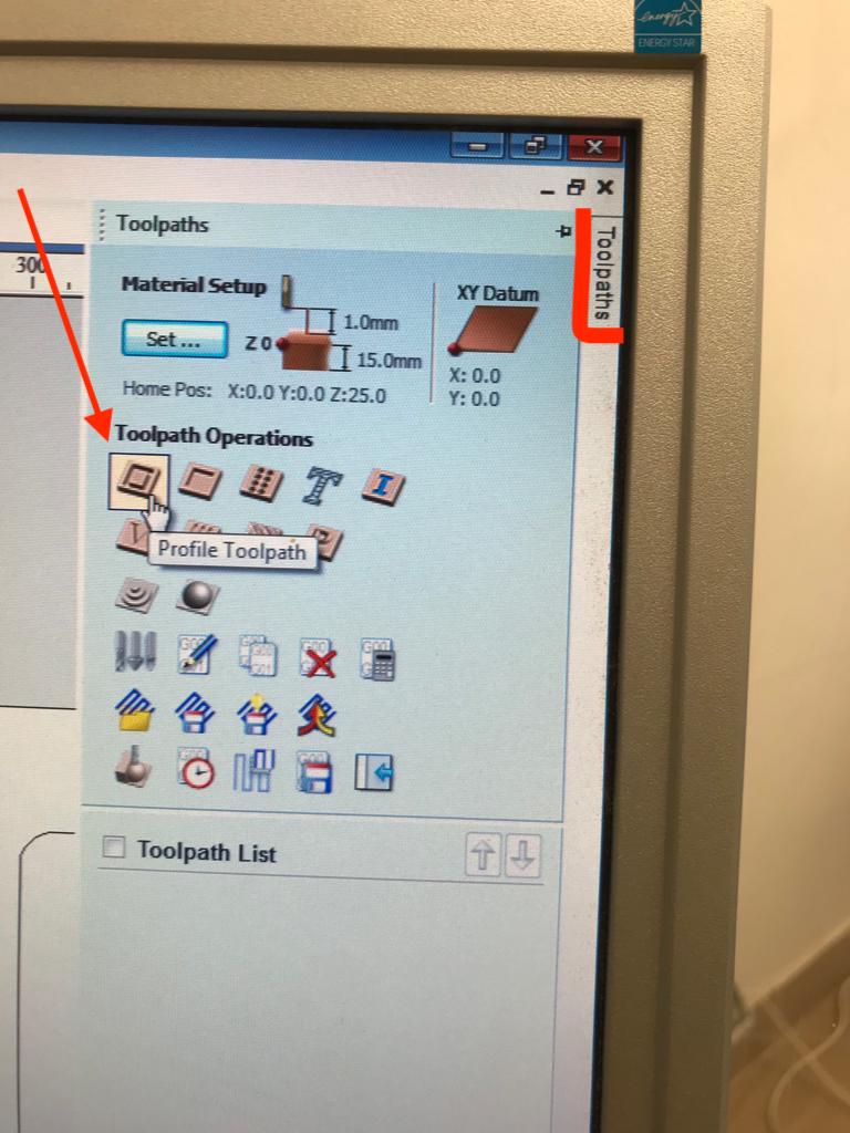
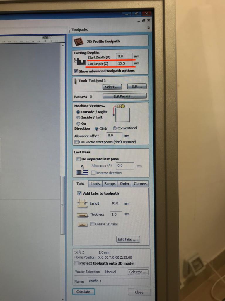
In the upper right corner we clicked on the "Toolpath" menu, and then "Profile toolpath" to have an external cut:
As a first first thing we set the start depth at 0.0 mm (because we want the machine to start cutting at origin of the z) and then the cut depth at 15.5 mm because our board is 15 mm deep and we wanted to be sure the cut was right.
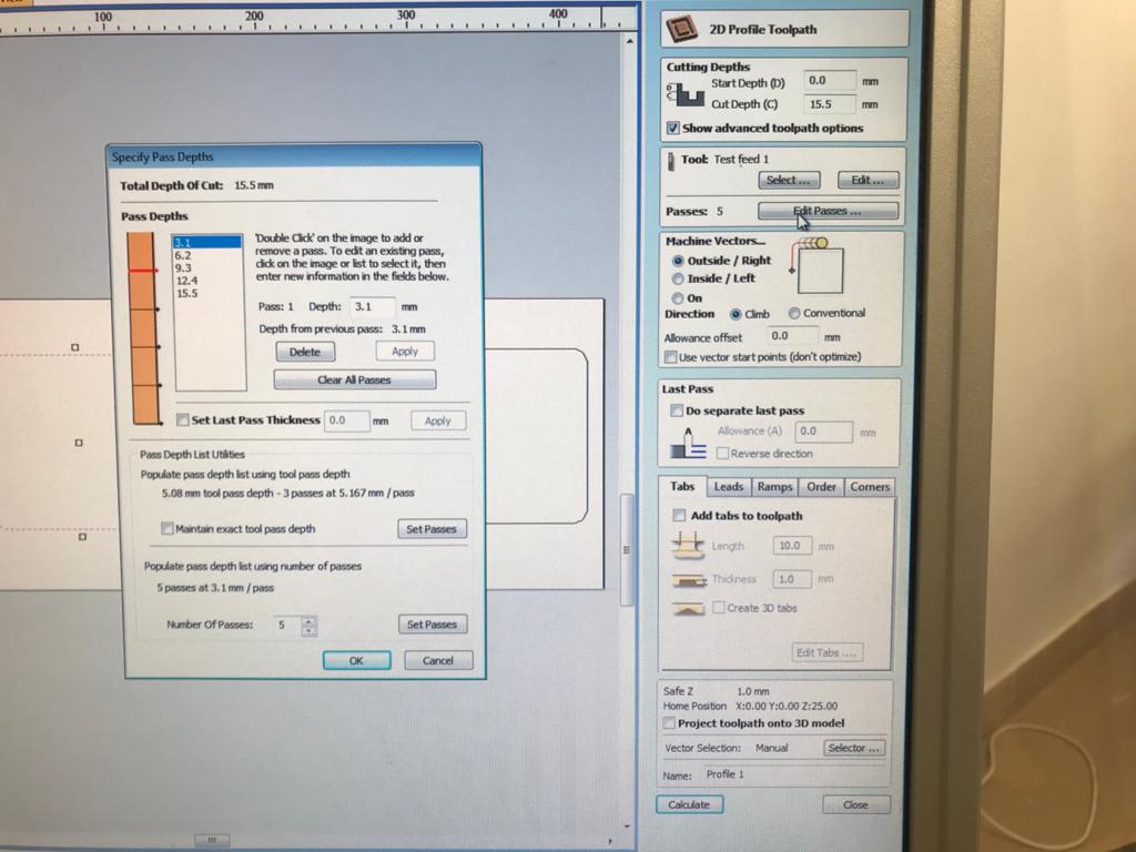
We selected our tool (with the feed rate changes) and then we set the passes to 5 (3 mm each is the safety limit):
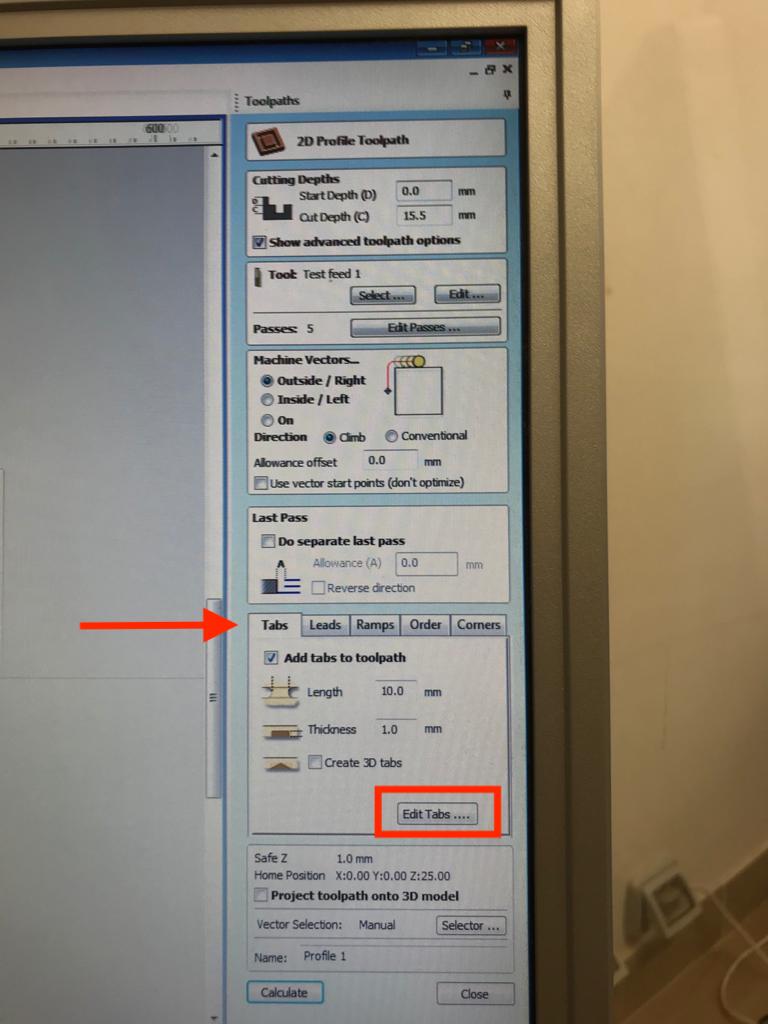
After that we selected an outside climb cut as shown in the image above. Then we added two tabs to the toolpath to make the object stable even when it's completely cut: tabs are just little pieces (10 mm width x 1 mm deep) to keep the cutted piece of wood anchored to the sacrificial layer. Clicking on "edit tabs" we were able to position as many as we wanted on the toolpath. The number and the position of the tabs depends on the shape to be cut, on the size and from the distance relationship with the other pieces on the table.
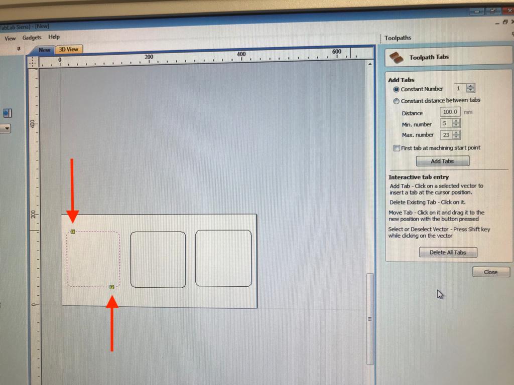
When all the settings are ready we pressed "calculate" to get the toolpath. This way we are able to see a preview of the selected toolpath.

The exact same procedure was made for the other feeds we wanted to test. We saved the toolpaths in 3 different VCarve files.
After this, we proceded on the Shopbot Control panel.
CUT CHECK TEST
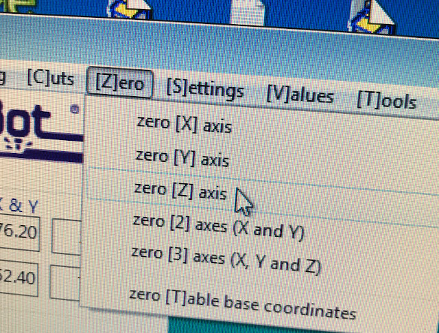
In addition to our test files, we created a separate 2D profile cut toolpath, changing the cut dept to 1 mm and setting a fake Z on the Shopbot control panel by clicking on
"Zero"-zero z axis.
air_cut from Olivia De Masi on Vimeo.
This test is important because it allows you to have a physical preview of the cutting process on air (because we setted a fake z). This way you can check the cutting path and make sure that the mill doesn't encounter obstacles, screwes above all.
Shopbot Control Panel Software
The software is just a control panel to move the axes and to import the files to be cut.
FOTO ________________________________________________________________________
Test 2: Pocket Climb vs Pocket Conventional cut
After positioning another wooden board onto the sacrificial layer, and securing it with screwes and washers. We proceeded with the second test.
This time we wanted to experiment between climb and conventional cut on a pocket, using the same three feed rate of test 1.
On VCarve, we set the size of the Canva based on our working area (200x200mm). Inside the Canva, we created 6 squares of 5 cm ( 3 squares for the climb pocket cut with 130, 105, 80 feed rate, and the other 3 squares for the conventional pocket cut).
We then moved the objects with the tool: Transform Objects - Move selected objects.
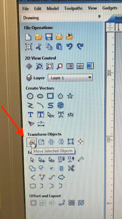
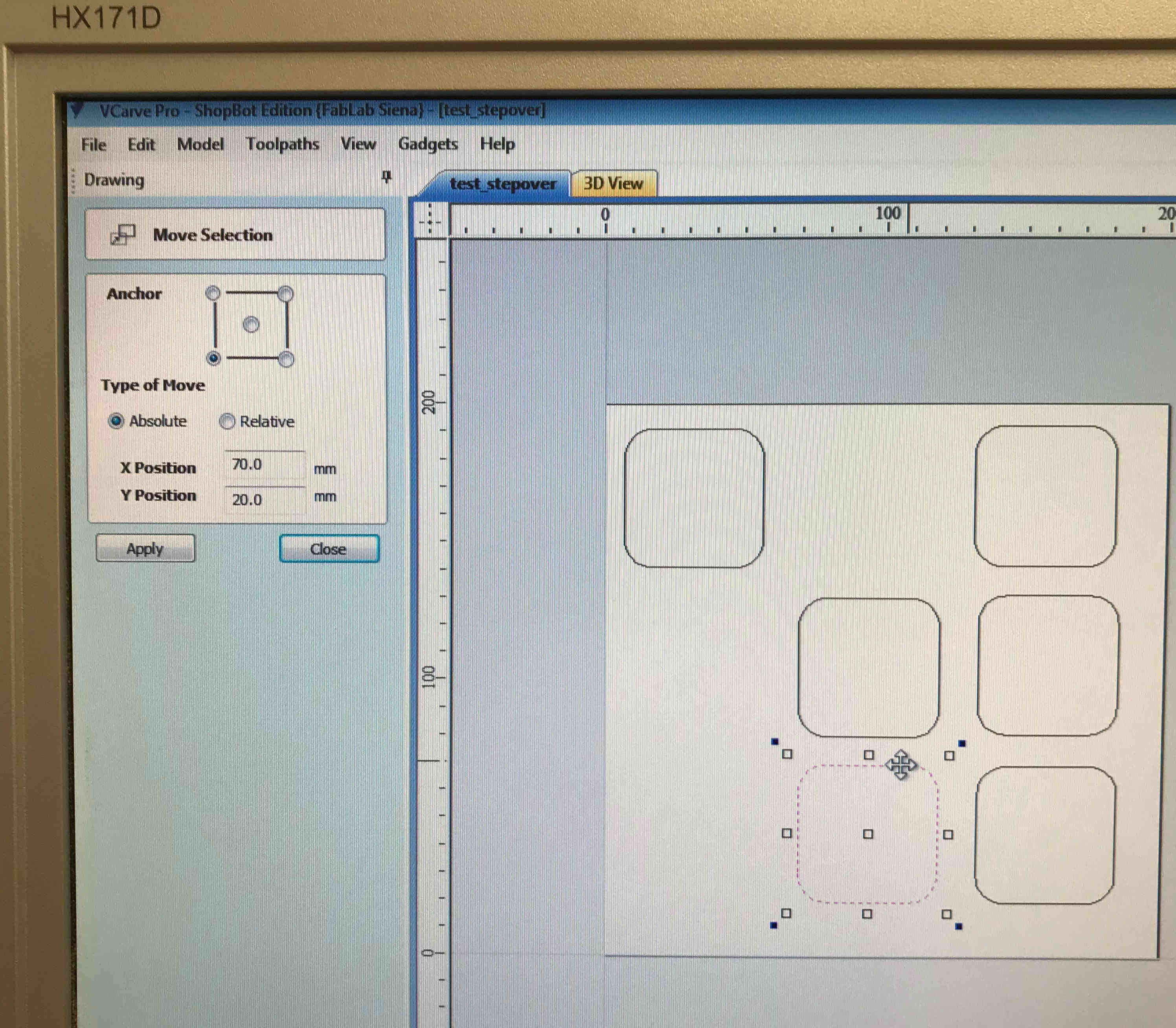
Once the selected tool menu was opened, we set the anchor on the down-left corner, and we matched that anchor with the same corner of the selected square, as the photo below shows.
Then, we set the type of movement as "absolute" and we set the coordinates for starting the cutting: y=20mm and x= 70mm (50, the side of a square + 20 mm as additional distance). We decided started cutting from x =70 mm to avoid the
We set a pocket toolpath for every square, with the same cut depth (12 mm), 4 passes ( to avoid the pass depth from exceeding 3 mm. During test 1 in fact, we saw that a pass depth that exceeds 3 mm is challenging for the mill and as a consequence, the machine screeches.)
We changed the mill feed rate. One square with 130, one with 105, and the other one with 80.
In the "clear pocket section" we selected raster and climb for 3 squares, and raster and conventional for the other three.
We set profile pass: last.
We changed the toolpath name, saved the settings with calculating and saved every test file, one at a time, including the "Cut test"
After checking the cut with the "Cut Test", we proceeded with the real cut for our pocket climb vs conventional cut test.
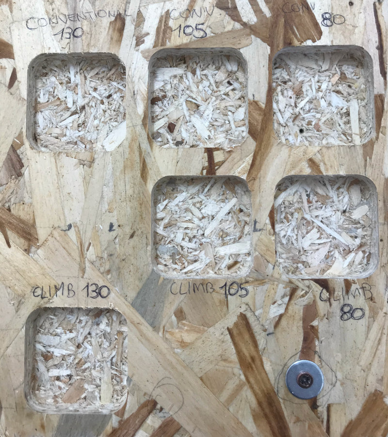
CONCLUSION We didn't find major differences between climb and conventional cut, not even while comparing the different feed rate.
Although we have noticed a lot of the pocket material residue left. Initially, we thought it could have depended by the different settings, but the residue was in all the 6 pocket squares.
Our Instructor suggested that the residue could be caused by the different humidity levels on different areas of the wooden board.