WEEK 3 - Computer-Controlled Cutting
INTRODUCTION
I spent a very rich week on assignments, gained a lot of information, and learned on machines I had never worked on before.
Assignment Description
- characterize your lasercutter's focus, power, speed, rate, kerf, and joint clearance
- cut something on the vinylcutter.
- design, lasercut, and document a parametric construction kit.
group assignment:
individual assignment:
for the group assignment you can get it here
Let's Start with the individual assignment
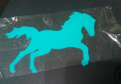
vinylcutter
First I had no experience cutting vinyl before,so let's take this journey together.
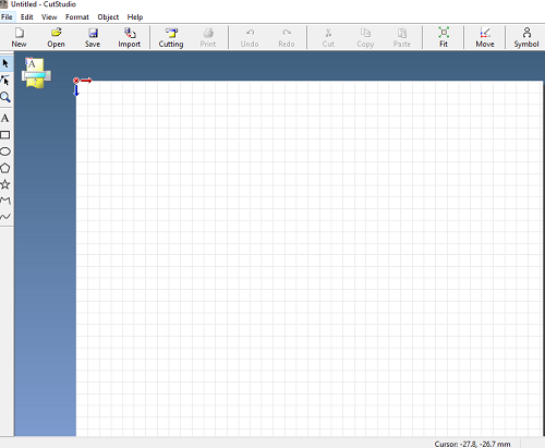
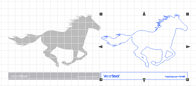
- I used CutStudio software, you can download it from here
- insall, and open it
- Now you have a very simple interface
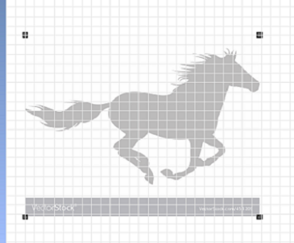
- drag and drop your image here to convert it to vector.
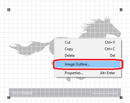
- Right click and choose"image outline"
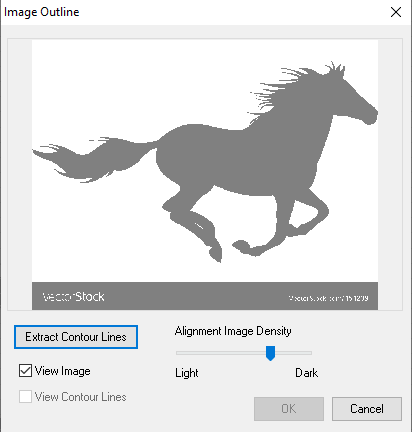
- click on extract contour lines, then ok
- now delete the image source
Now! let's go with Vinylcutter
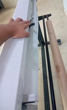
- On the machine we have clamps to install the workpiece, and to define the locations of the sensors
- The first clamp should be placed in front of the first sensor, and the last at the end of the workpiece in front of the sensor
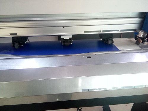
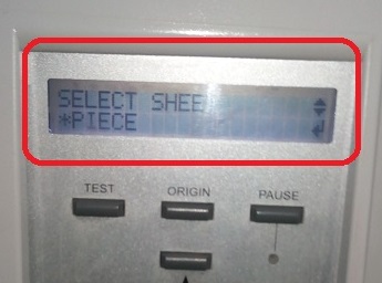
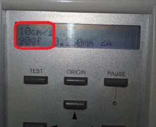
- Turn on the machine, place your work piece with clamps, then choose the "piece" option, and i worked with 90gf for force
- connect your machine with the laptop
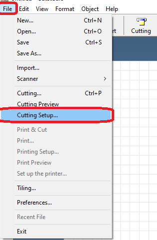
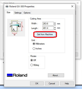
- click on file, then cutting setup
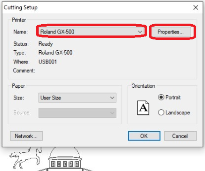
- choose your machine, then get your dimension
- put your design on correct place, and press on cutting
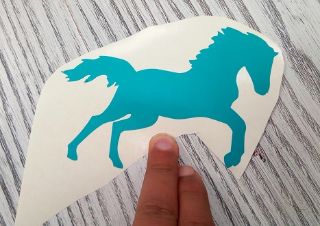
- Get your product and remove everything you don't want
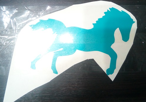
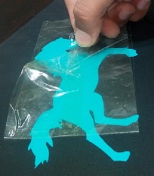
- Apply tape to the product and pull it vertically
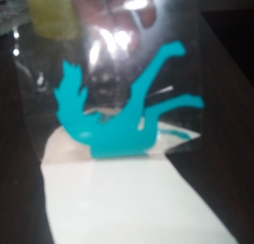
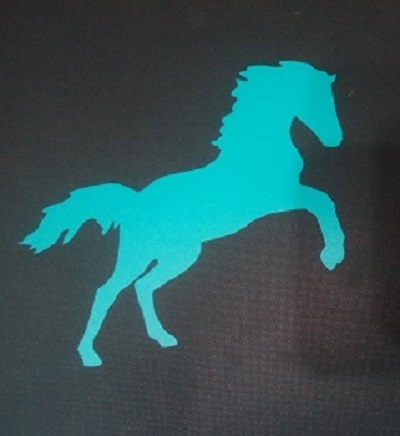
- Then put it as you like, then slowly pull the tape at a small angle
finally
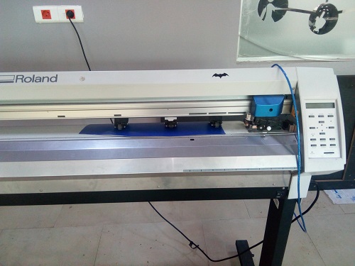
our machine is Roland GX-500
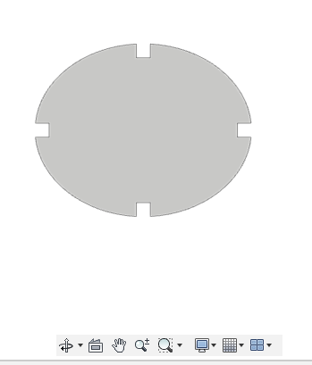
parametric construction kit
What is a Parametric Modelling?
Parametric is a term used to describe a dimension’s ability to change the shape of model geometry as soon as the dimension value is modified. Feature-based is a term used to describe the various components of a model. For example, a part can consists of various types of features such as holes, grooves, fillets, and chamfers. A ‘feature’ is the basic unit of a parametric solid model. for more details here
I used Fusion 360
- Design the first piece as a new component
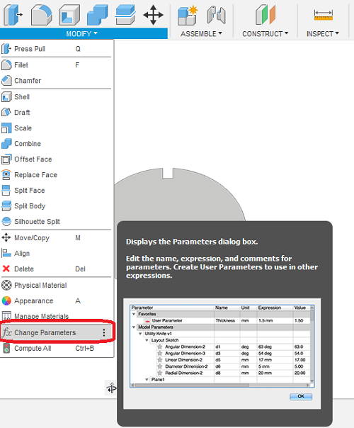
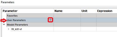
- choose change parameters from modify
- choose user parameters, press on "+"
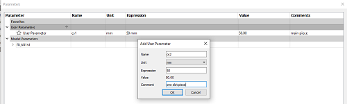
- enter your parameter name and value, then click ok
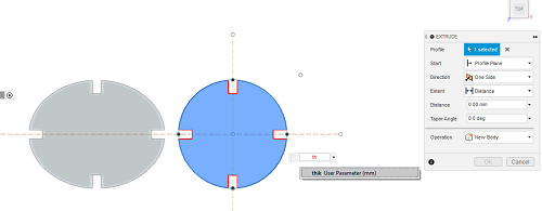
- and when you need to set dimensions, just write the name of parameter
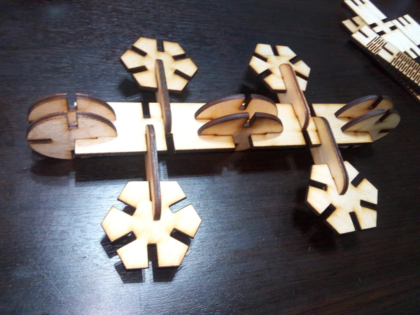
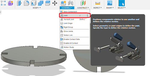
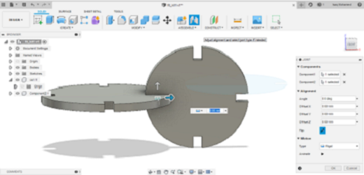
- you can try to assembly your kit, go to assembly, press on join,then choose the places you need to join together
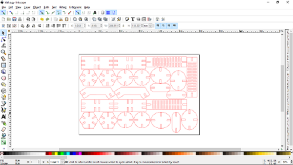
- export your file as a dxf file
- i used inkscape programe
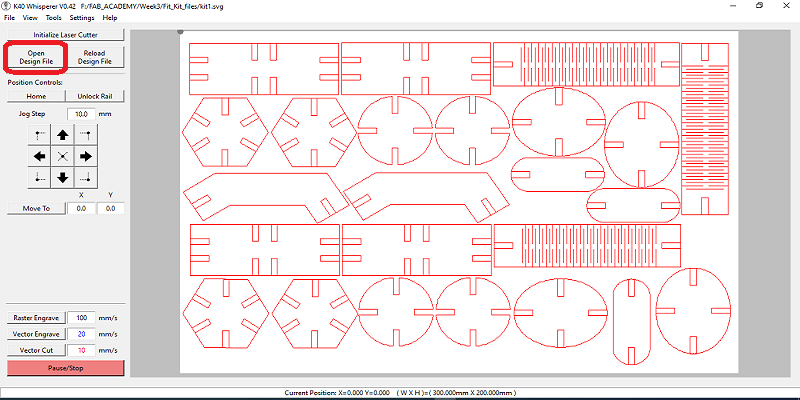
- I used K40 software for my machine, you can download it from here
- easy to use, open it, and upload your SVG or DXF file (from open design file button)
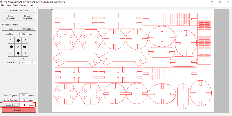
- I have set the power vector cut on 10
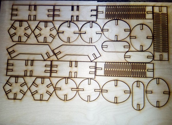
- enjoy
laser cutting