Laser Cutter
The first mission group, and the first amazing teamwork.
Assignment Description
- Characterize your laser cutter's focus, power, speed, rate, kerf, and joint clearance.
- Document your work (individually or in group).
- Upload it to the class archive.
Task distribution
- group to search and obtain test files.
- group for implementation.
- group to create the website and documents.
We divided ourselves into 3 groups:
- 3mm Plywood
- 3mm Acrylic
Materials used:
Machine settings:
Set the machine origin.
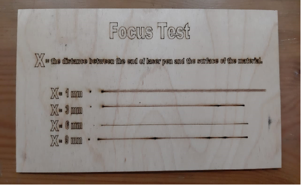
A) To characterize the cutter’s focus:
- We designed a test panel for dots and lines on illustrator.
- Imported the design file to RD Works.
- Connected the P.C to the laser cutter.
- Tested the frame of our design whether it fits into our material border. (Go scale).
- Adjusted the focus distance and pressed start for each X.
We tried to assign the distance that provides the optimum focus.
- We designed a test grid of squares on illustrator.
- Imported the design file to RD Works.
- Assigned a different layer with different power and speed characteristics to each square.
- Connected the P.C. to the laser cutter.
- Tested the frame of our design whether it fits into our material border. (Go scale).
- Pressed start
- The outcome result was a very good indicator of the characteristics we want to test.
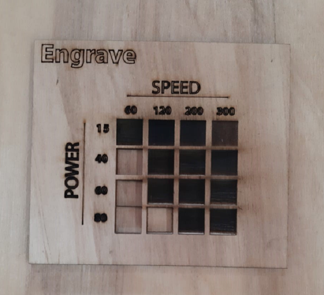
B) To characterize the cutter’s power vs. speed:
I) For Cutting:


- We designed a test grid of squares on illustrator.
- Imported the design file to RD Works.
- Assigned a different layer with different power and speed characteristics to each square.
- Connected the P.C. to the laser cutter.
- Tested the frame of our design whether it fits into our material border. (Go scale).
- Pressed start
- The outcome result was a very good indicator of the characteristics we want to test.
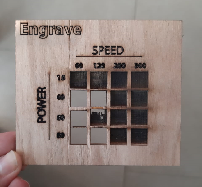
II) For Engraving / Scanning:
- We designed a grid of 10 squares inside a rectangular border on illustrator.
- Imported the design file to RD Works.
- Connected the P.C. to the laser cutter.
- Tested the frame of our design whether it fits into our material border. (Go scale).
- Pressed start
- We measured the accumulated kerf and divided it by the number of cut sides between the ten squares. Which was 10.:D
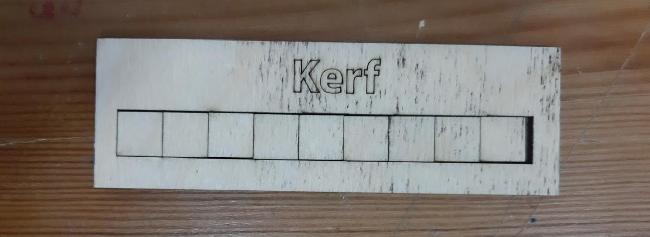
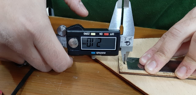
C) To characterize the cutter’s kerf:
The measurement was 2.1 mm.
The kerf = 2.1 / 10 = 0.21 mm.kerf
Failures and findings:
As we can see in the following image, square (40-120) was totally gone, and that is illogical given that there were traces of square (60-120).We found out that the wood we used had a slight bending upwards, that’s why test results weren’t accurate.