WEEK 2 - Computer-Aided Design
INTRODUCTION
Initially, I have some experience with CAD software, and I'm used to AutoCad, Inkscape and Inventor,
so I think this is the best time to explore other CAD software.
I decided to go through CorelDraw for 2D Design, and Fusion 360 for 3D Modeling.
Assignment Description
- model (raster, vector, 2D, 3D, render, animate, simulate, ...) a possible final project.
- Explore CAD software.
- Upload it to the class archive.
Start with sketching
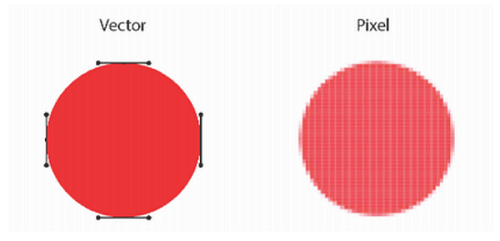
- What is a raster image? Raster images, also known as bitmaps, are comprised of individual pixels of color. Each color pixel contributes to the overall image. Raster images might be compared to pointillist paintings, which are composed with a series of individually-colored dots of paint. Each paint dot in a pointillist painting might represent a single pixel in a raster image. When viewed as an individual dot, it’s just a color; but when viewed as a whole, the colored dots make up a vivid and detailed painting. The pixels in a raster image work in the same manner, which provides for rich details and pixel-by-pixel editing.
- What is a vector image? Unlike raster graphics, which are comprised of colored pixels arranged to display an image, vector graphics are made up of paths, each with a mathematical formula (vector) that tells the path how it is shaped and what color it is bordered with or filled by. Since mathematical formulas dictate how the image is rendered, vector images retain their appearance regardless of size. They can be scaled infinitely. Vector images can be created and edited in programs such as Illustrator, CorelDraw, and InkScape (don’t worry, these visual editors do the math for you).
- This link is more useful for the difference between Vector and Raster here.
Now! let's go with CorelDraw
- to download this softwareDownload.
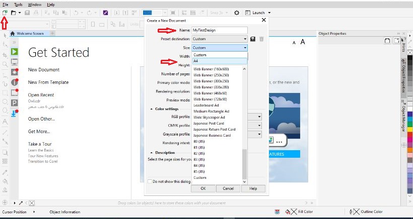
- Open it and click on new file
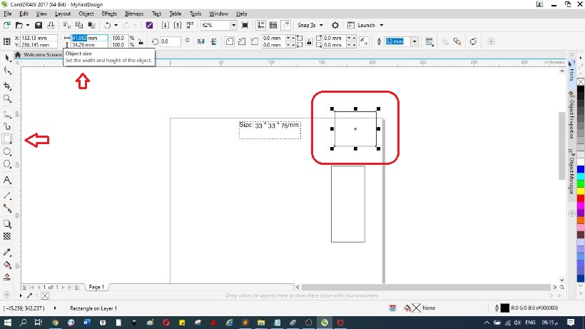
- set the name and size you want
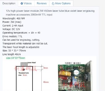
- Now I need to design a laser diode base, I have found this dimensions on this siteUGE
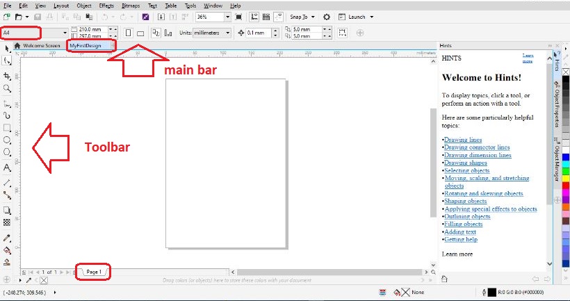
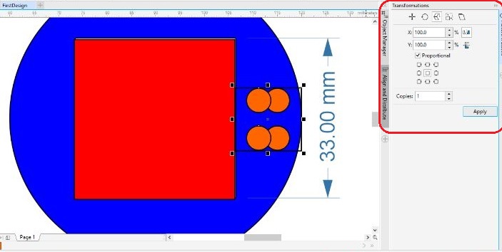
- in this program you can draw easily, just choose the tool from toolbar, and edit the dimensions from the main bar
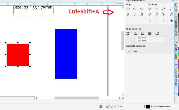
- To align your objects, press Ctrl + Shift + A
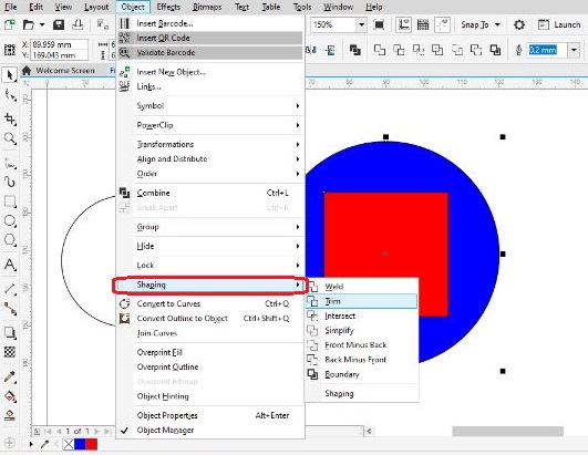
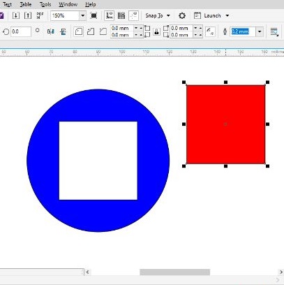
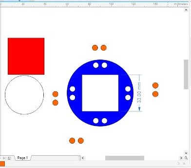
- To trim two objects from one another press object then shaping and trim
- to repeat objects with orientation click on object and choose transformation manager
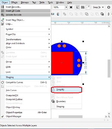
- To trim group of objects from another one press object then simpify
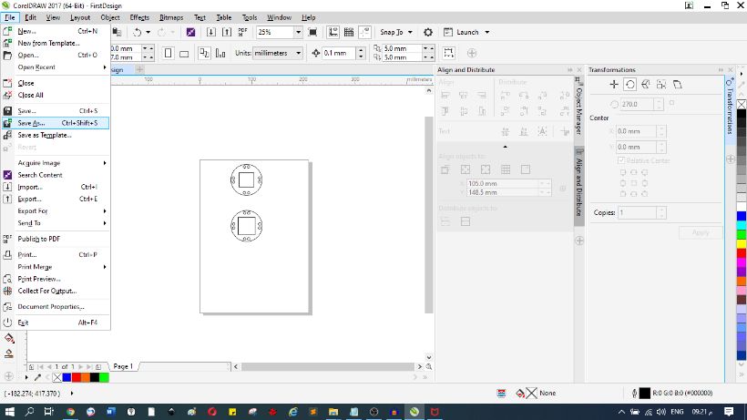
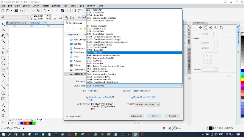
- To save the design as a dxf file go to file then choose save as and choose dxf file
 .
.
3D Modeling
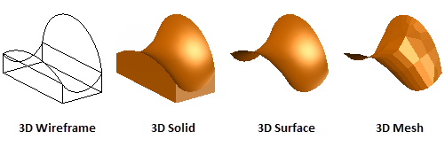
there are 3 types of 3d objects:
- Solid modelling involves working with pre-defined shapes, such as cubes, cylinders, spheres and other polyhedrons, to add features or cut material away. It is typically used in mechanical and construction based applications, where specific parameters, measurements and shapes are more defined. Objects can also be cut open to reveal their internal features, and even stress tested as if they were objects in the real world. Solid modelling can be difficult to work with if you’re wanting to design more organic, amorphic shapes, so is less suited to artistic and creative applications.
- With surface modelling, you work with vectors and tangents, manipulating the shape by “pulling and pushing” on control points (generally where tangents intersect) to fashion shapes that are more amorphic or fluid in nature. You can easily twist, turn, and bend surfaces. With surface modelling, you can design more organic shapes which would be hard to design in solid modelling software. Therefore, surface modelling is typically used by artists who wish to create pieces which have a focus on aesthetics and flow.
- Mesh modelling is similar to surface modelling. However, every curved surface, unlike the perfectly smooth vector surfaces you get with surface modelling, is made up of numerous flat triangular polygons. These polygons can be thought of as “pixels”, with each object having a defined resolution. In other words, the more polygons, the smoother the object appears. However, when you zoom in close, you’ll notice that the polygons that make up the curved surface are still flat. This may seem a little backward, however, it means that complex objects are easier to define mathematically. Therefore, mesh based models are easier to display in a range of different 3D design programs, and less data intensive when it comes to 3D printing the object.
Solid
Surface
Mesh
For more details this is a good link
Hint:
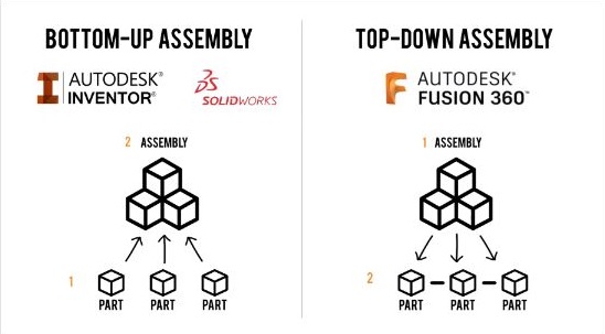
The main difference between Fusion 360 and other 3D software is the process from 2D to 3D assembly
let's start with fusion 360
- you can download it from here
- If you don't have an account, create one, then download and open it
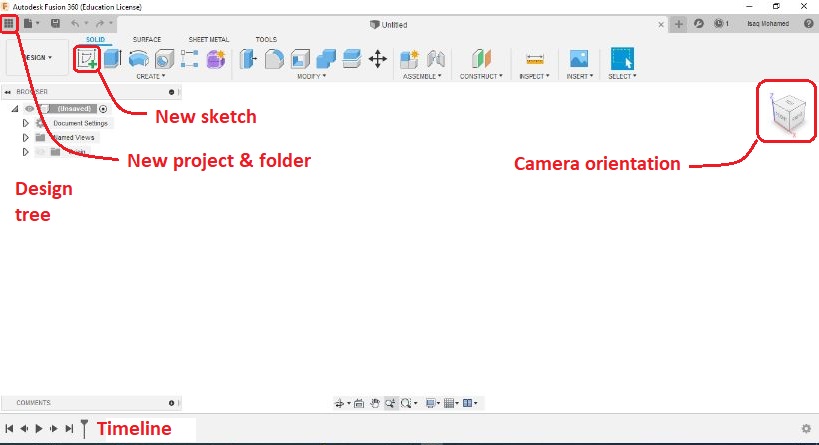
- this is the first page
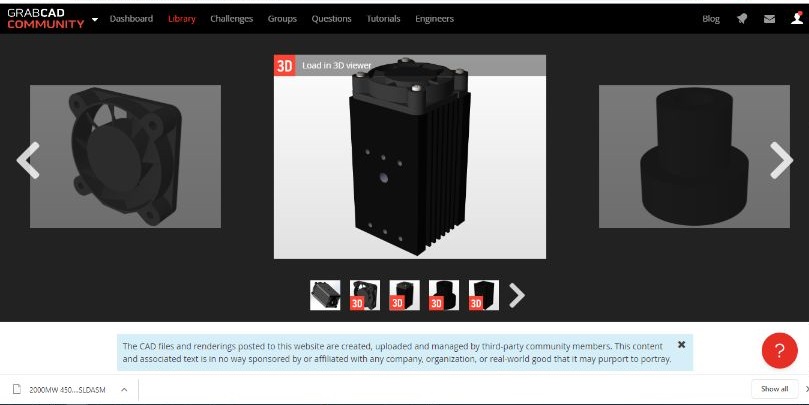
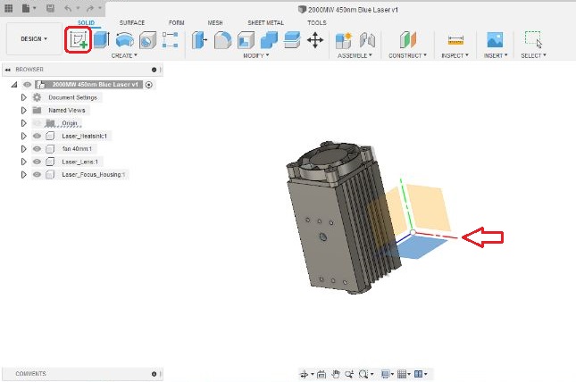
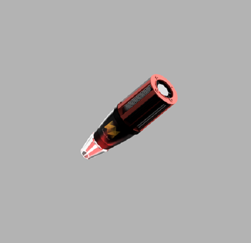
- Now I'm going to design a laser pen hand, and I need a 3D laser diode model, so I went to the grabcad site, it's a big open source community, just creat an account and enjoy here
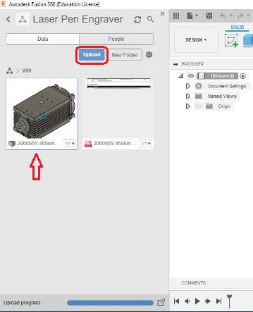
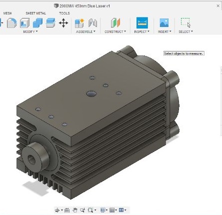
- upload your design and press double click on it to appear on the page
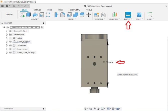
- check your dimension from Inspect tool
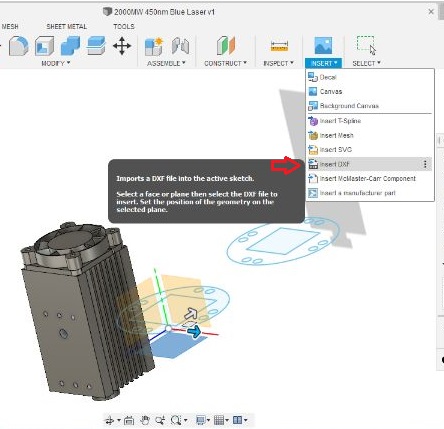
- click on new sketch then choose the plane you want
- i inserted my dxf file, and i pressed on finish sketch then i chose extrude, but i faced issue, i couldn't extrude all features once, so i decided sketch the base from scrach on fusion 360
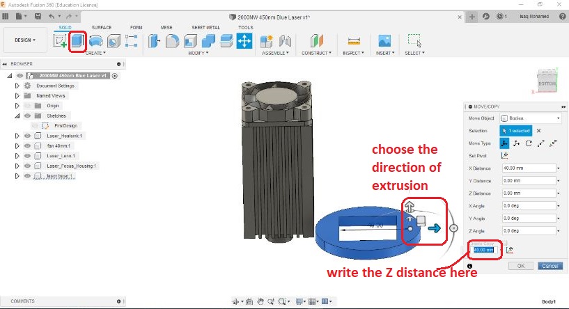
- click on new sketch, then choose the plane, i chose upper face of fan to sketch the base
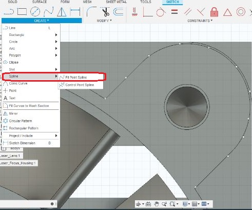
- i used spline to re-design this face to get the base, then click on finish sketch and press on extrude(3mm z)
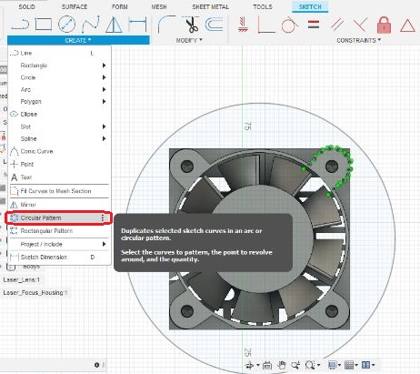
- sketch again on another plane from base, create rectangle, and choose pattern to repeat it, then finish sketch and extrude to get columns to support the base
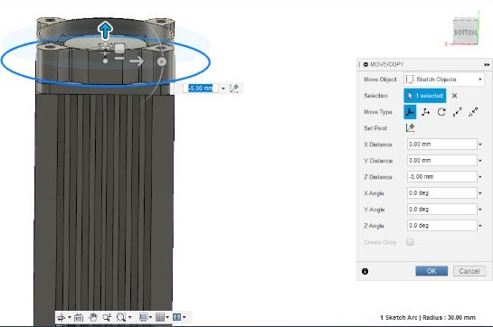
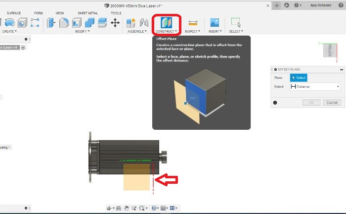
- Now I need to design the distance between the laser lens and the workpiece. choose construct then offset plane
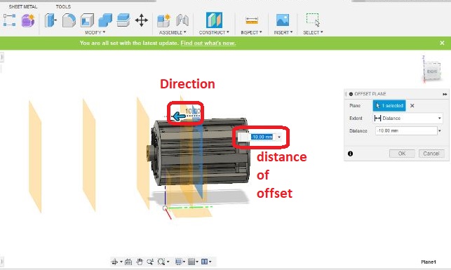
- choose the face or plane to put your new plane, then choose the direction, and the distance
- I designed 3 planes
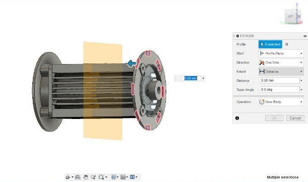
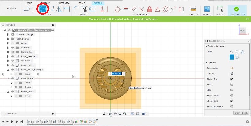
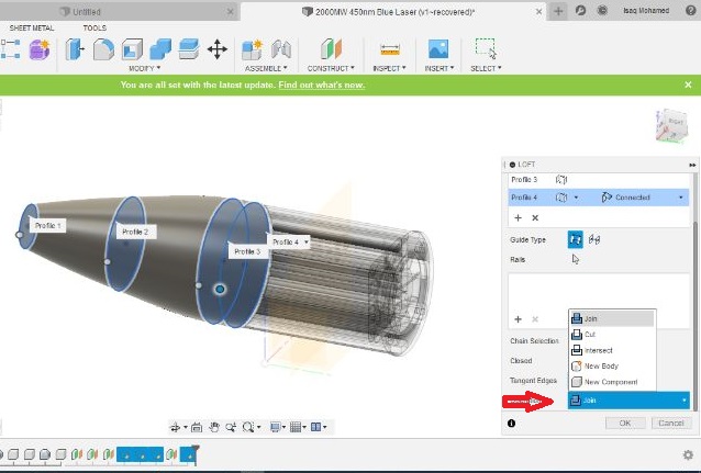
- press on new sketch, then choose the first plane then Design a circle on it, repeat that on all planes, and set gradual dimensions, so that they are the smallest at the end
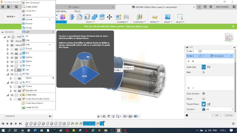
- Choose loft from drop list of create, then choose all planes, and choose join
all documents here