WEEK 8 - Embedded Programming
INTRODUCTION
Assignment Description
- Read a microcontroller data sheet.
- Program your board to do something, with as many different programming languages and programming environments as possible.
- Optionally, experiment with other architectures.
Datasheet
Why do we need to read the datasheet?
- You need to know the pinout for your own Microcontroller
- One of the first tables in most datasheets will be Absolute Maximum Ratings, You don't want to damage your Micro, of course
- like voltage and current ratings
- timing diagrams, You need to know how your Microcontroller responds
- You need to know the microcontroller architecture and interior specifications like: (Memories, clocks,... )
- for more details get it from here
- and here how to read a datasheet
Now! let's go with ATtiny44 datasheet
First, what is the meaning of microcontroller?
A microcontroller is a compact integrated circuit designed to govern a specific operation in an embedded system. A typical microcontroller includes a processor, memory and input/output (I/O) peripherals on a single chip. Sometimes referred to as an embedded controller or microcontroller unit (MCU), microcontrollers are found in vehicles, robots, office machines, medical devices, mobile radio transceivers, vending machines and home appliances, among other devices. They are essentially simple miniature personal computers (PCs) designed to control small features of a larger component, without a complex front-end operating system (OS).
For more information go to this site
- Download datasheet here
- and SUMMARY DATASHEET.
- Features:
- High Performance, Low Power AVR®8-Bit Microcontroller•
- Non-Volatile Program and Data Memories>> 2/4/8K Bytes of In-System Programmable Program Memory Flash
- Operating Voltage: 1.8 – 5.5V for ATtiny24V/44V/84V – 2.7 – 5.5V for ATtiny24/44/84
- Industrial Temperature Range: -40°C to +85°C
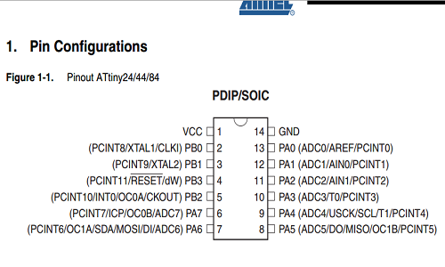
- Pin Configurations
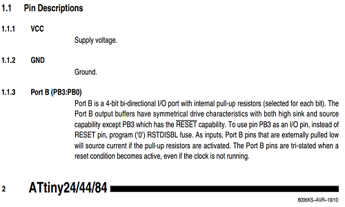
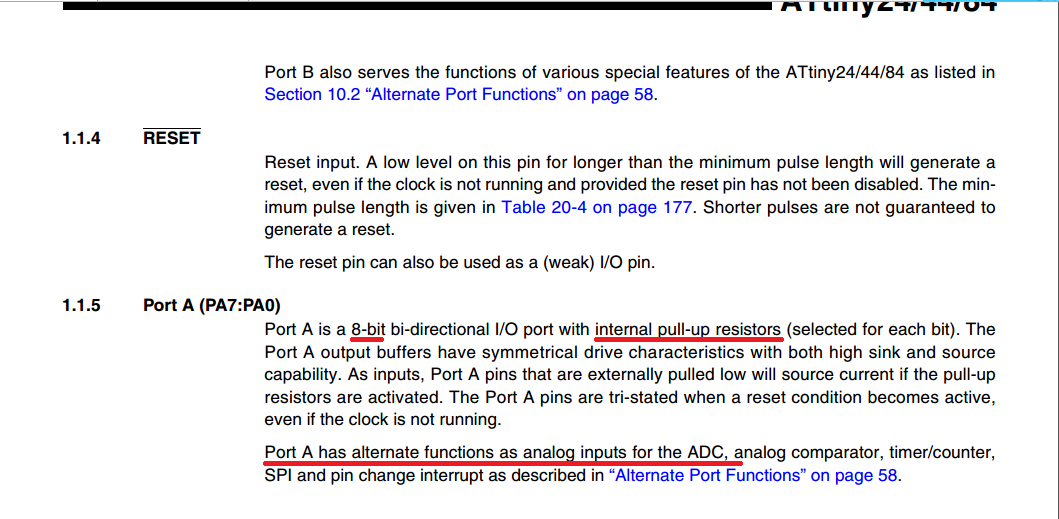
- Ports(B&A)
- The most important differences between Port A&B.
- Port B has 4 pins I/O digital
- Prot B has RESET pin in PB3
- Port A has 8 pins I/O digital, also in the same pins there is an ADC, so we can use it as analog input
- Port A has ISP pins
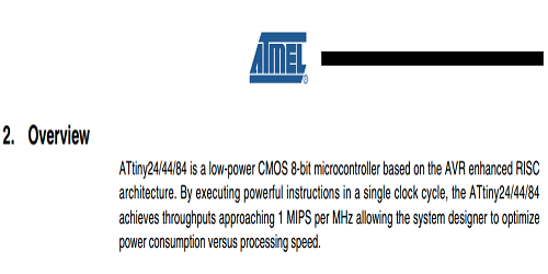
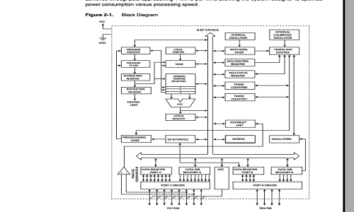
- Overview of architecture
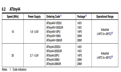
- Power and speed
- I used Arduino IDE
- and I used the hello_echo board, you can find it at the electronics design week
- connections
- you can see all the steps here
Arduino Pin 13 ---> SCK
Arduino Pin 12 ---> MISO
Arduino Pin 11 ---> MOSI
Arduino Pin 10 ---> RESET
Arduino 5V ---> VCC
Arduino Ground ---> GND
Code
// constants won't change. They're used here to set pin numbers:
const int buttonPin = 8;     // the number of the pushbutton pin
const int ledPin =  7;      // the number of the LED pin

// variables will change:
int buttonState = 0;         // variable for reading the pushbutton status

void setup() {
  // initialize the LED pin as an output:
  pinMode(ledPin, OUTPUT);
  // initialize the pushbutton pin as an input:
  pinMode(buttonPin, INPUT);
}

void loop() {
  // read the state of the pushbutton value:
  buttonState = digitalRead(buttonPin);

  // check if the pushbutton is pressed. If it is, the buttonState is HIGH:
  if (buttonState == HIGH) {
    // turn LED on:
    digitalWrite(ledPin, HIGH);
  } else {
    // turn LED off:
    digitalWrite(ledPin, LOW);
  }
}
Note: I used Button example from Arduino examples,just I have changed the pins number
Download all files from here