input Device
My Issue
As COVID19 affect, the complete quarantine took place this week in my country, which makes it difficult to go to the lab ,as all shipping companies canceled shipping operations to us, and I was in the process of receiving a shipment of electronics from DigKey that I will need for my project and to carry out the tasks of these week.
I've Built my board in Electronics Design week
Test input device (sensors)
A sensor is a device that detects and responds to some type of input from the physical environment. The physical input could be light, heat, motion, moisture, pressure, or any one of a great number of other environmental phenomena. I was test alot of sensors :
1- Temperture Sensor:

In Lm 35 the output voltage is linearly proportional to the Celsius (Centigrade) temperature.
Features:
 * Calibrated directly in ° Celsius (Centigrade)
 * Linear + 10.0 mV/°C scale factor
 * 0.5°C accuracy guaranteeable (at +25°C)
 * Rated for full −55° to +150°C range
 * Suitable for remote applications
 * Low cost due to wafer-level trimming
 * Operates from 4 to 30 volts
 * Less than 60 μA current drain
 * Low self-heating, 0.08°C in still air
 * Nonlinearity only ±1⁄4°C typical
 * Low impedance output, 0.1 W for 1 mA load
I've used LM35 in simple alarm system this system lights ON LED when the Temprature is above the disired value ( 21 C in my code which programmed by Arduino IDE and using arduino board as ISP to programm my board In this part I followed this documentation .
Here is the code which downloaded to my board.
int sensorPin = A0;
float voltage, temperatureC, reading;

void setup() {
pinMode(3, OUTPUT);
}
void loop() {
reading= analogRead(sensorPin);
voltage= reading*5.0/1024;   // This eqution converts anloge amount to voltage

temperatureC=(voltage)*100;  // This equation  converts the voltage to Temperture as Datsheet of LM35

if (temperatureC>21)
{   digitalWrite(3, HIGH);   }
 else { digitalWrite(3, LOW);  }
}
To connect LM35 you need to connect the Vs --> 5v and Vout --> A0 and GND --> GND, I use the external power supply to feed my board here in figure bellow.
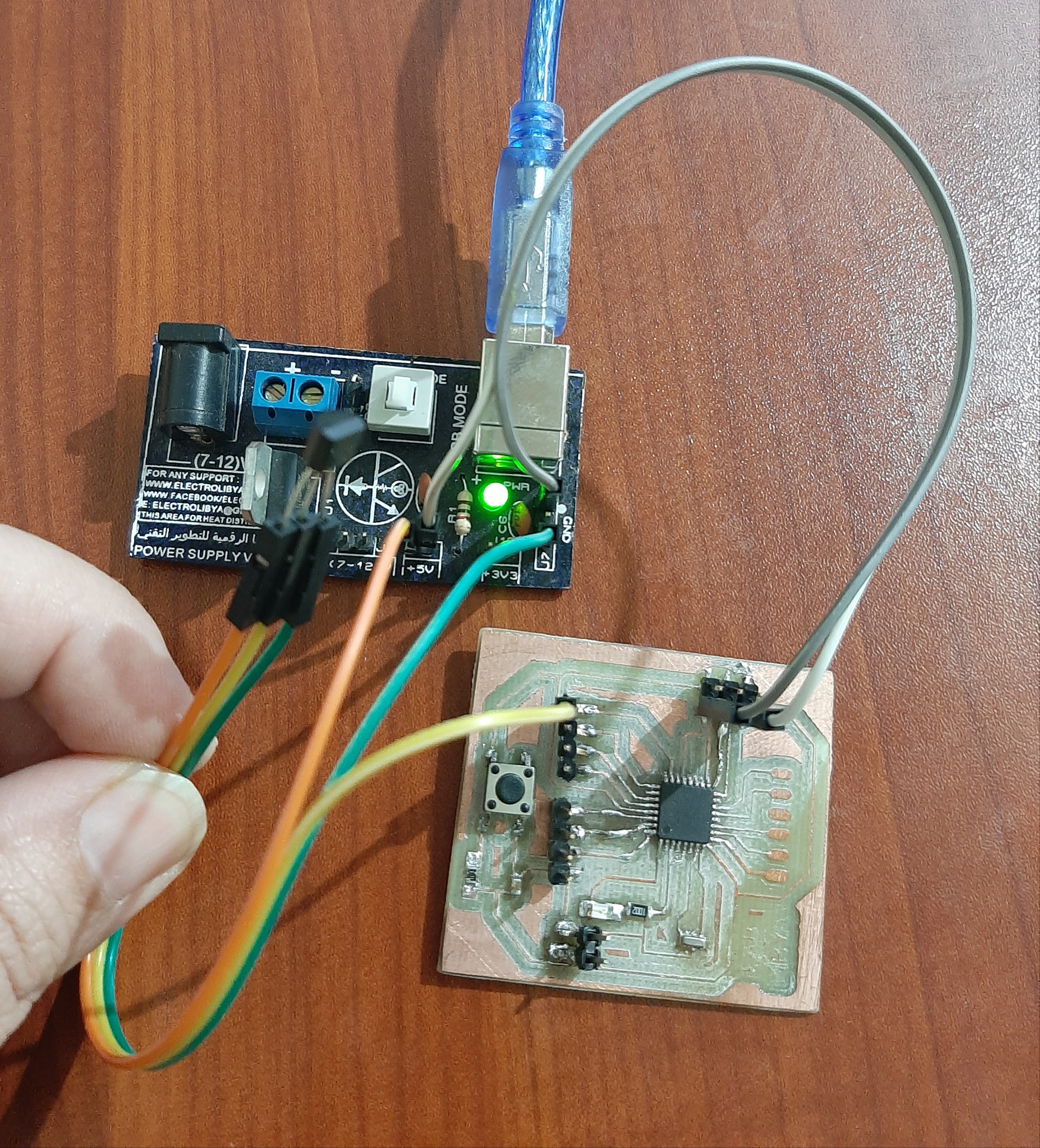
I've tested the LM35 with my hand to increase the tempertureand this test gives a good result as shown in vedio below:
2- Solar Cells
A solar cell, or photovoltaic cell, is an electrical device that converts the energy of light directly into electricity by the photovoltaic effect, which is a physical and chemical phenomenon.
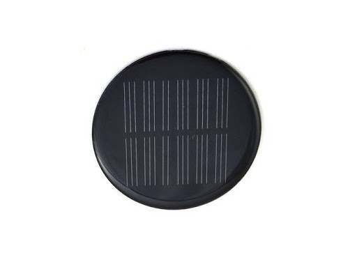
Nominal voltage: 2V, idle voltage: 2.4V, nominal current: 100mA. Short circuit current: 112mA.
I need to test my solar cell Cause it's apart of my final project and i need to know the output voltage that Actually give, I have use arduino board because it similar to my board that I've designed with Atmega 328p
void setup() {
                      // initialize serial communication at 9600 bits per second:
  Serial.begin(9600);
}

void loop() {
                      // read the input on analog pin 0:
  int sensorValue = analogRead(A0);
                    // print out the value you read:
  Serial.println(sensorValue);
  delay(1);        // delay in between reads for stability
}
I've tested by decrease the light passes .