Embedded Programming
Group Assigment
This week we have to read the microcontroller data sheet However, due to my scientific background and experience in the microcontrollers and embedded systems ( as I'm a tutor of these two subjects)That means I had read many of data sheets of different microcontroller,So I summed up a comparison between two types of microcontrollers, in terms of Data bus/ instruction,clock,Program Memory,Internal Oscillator,RAM,..act.
Compartor between Atmega328 and PIC 18F432 and STM 8
| Feature and Specification | PIC 18F432 | Atmega328 | STM8 ARM | Data bus/ instruction | 16 bit | 8 bit | 8 bit |
|---|---|---|---|
| clock | 40 Mhz – 10MIPs | 20Mhz – 20MIPs | up to 24Mhz |
| Program Memory | 8 Kbyte | 32 kbyte | up to 128 Kbytes |
| Internal Oscillator | 8Mhz, 32Khz | 8MHz | 128 kHz RC and user-trimmable 16 MHz RC |
| RAM | 1536 byte | 2 kbyte | up to 6 Kbytes |
| I/O Ports | 40 | 28 | Up to 68 I/Os on an 80-pin |
| A/D convertor | 10 bit resolution / 13 channel | 10 bit resolution / 6 channel | 10-bit ADC with up to 16 channels |
| Serial communication | 1 x USART 1 x SPI 1 x I2C | SPI Serial 2x USART 2x Two-wire Serial Interface | UART,SPI,I2C,active beCAN 2.0B | EEPROM | 256 | 1Kbytes | up to 2 Kbytes |
| Operating Voltage (V) | 2-5.5V | +1.8 V TO +5.5V | +3.3 To +5v |
Individual Assigment
First of all I will describe how can I download load the code by using arduino,In my satuation I didn't have SMD IC in my country that's why I didn't made my ISP, After search I find these steps and follow them:
1- Burning the Bootloader
because I took it out of an Arduino board, I can skip this section
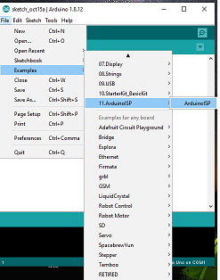
2- Load Arduino ISP Examples > ArduinoISP > ArduinoISP .
To upload the sketch to your Arduino board – the one that you will use as the programmer – you need to select board type and port.
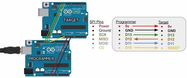
3- The programming process uses VCC, GND and four data pins. Three pins connect MISO, MOSI and SCK between the programming micro and the target micro, the fourth pin from the programming micro goes to the reset pin of the target.
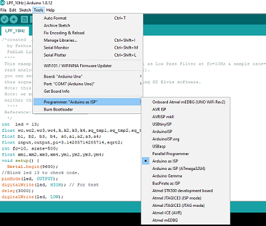
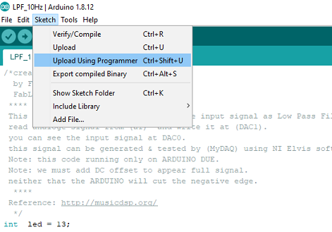
4- Load the sketch file in the target microcontroller or board open target code > sktech > upload using programmer, don't forget to choose in Tools --> Programmer -->Arduino as ISP
* My Issue
At the first time I was unable to download the program to my circuit board, It was appeared this message "The avrdude complains about the device signature being 0x000000:" at Arduino IDE, I didn't know what the meaning of this Error?and why?...after a lot of search and time I can't get why this error occurred , I was check my connection and check my programm steps but still the same error, figure below shows this Error
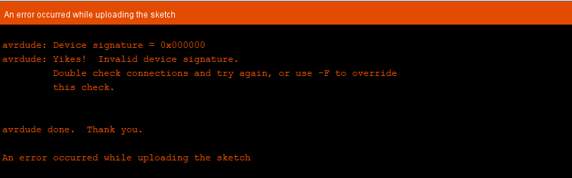
Finally I've double checked every trace in my circuit board with IC connection, then I find bad connection between SCk and IC, After resold this connection the program downloaded successfully ^_^
* Programing Arduino Board
This semester my students faced some problem in their project; they need a low pass filter as part of their project. wherefore I decide to help them in digital filter design, in this week I will illustrate "how to implement low pass filter by using arduino code?"
There are two types of digital filter FIR (Finite Impulse Response)and IIR (infinite impulse response),I use IIR which define as a recursive filter in that the output from the filter is computed by using the current and previous inputs and previous outputs. Because the filter uses previous values of the output, there is feedback of the output in the filter structure. The advantage of IIR filters over FIR filters is that IIR filters usually require fewer coefficients to execute similar filtering operations, that IIR filters work faster, and require less memory space. IIR equation describes as figure below:
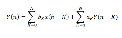
TO convert this equation to arduino code I find this useful web site
output=a0*input+a1*xm1+a2*xm2+a3*xm3+a4*xm4-b1*ym1-b2*ym2-b3*ym3-b4*ym4;
where a's and b's are filter coefficients:
a_tmp=4*wc2*k2+2*sq_tmp1+k4+2*sq_tmp2+wc4;
b1=(4*(wc4+sq_tmp1-k4-sq_tmp2))/a_tmp;
b2=(6*wc4-8*wc2*k2+6*k4)/a_tmp;
b3=(4*(wc4-sq_tmp1+sq_tmp2-k4))/a_tmp;
b4=(k4-2*sq_tmp1+wc4-2*sq_tmp2+4*wc2*k2)/a_tmp;
a0=wc4/a_tmp;
a1=4*wc4/a_tmp;
a2=6*wc4/a_tmp;
a3=a1;
a4=a0;
I test LPF(low pass filter) with cutoff frequency 10Hz that's why I chosse fc=10, srate=500 ,after upload the filter code
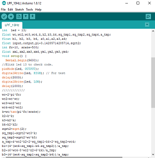
I use DUE board cause it have digital to analoge convertor (DAC) then we can get the output as analoge signal (not PWM as other boards).
To upload a sketch:
1- choose Arduino Due (Programming port)we need to from the Tools > Board menu in the Arduino IDE I didn't find it, for this I use board manger for Tools and download it as shown in figure below
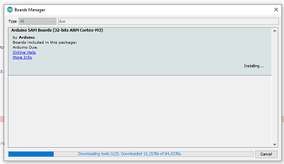
2- don't forget to close and open arduino IDE and be sure you select the correct serial port from the Tools > Serial Port menu.
3- upload LPF_10Hz sketch
The easy way to test the filter effect by using Serial Ploter from Tools. I plot dual signal befor and after by using Serial.print where filter (which respresnt with blue line) and signal after filter (which respresnt with blue line)
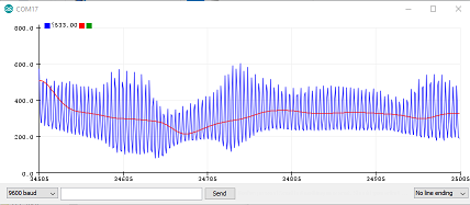
This signal is noise signal that generated by touch analoge input pin (A0) during running code as shown in video below
I've tested the same code with my board and MyDAQ device I've used MyDaq to visulize my data.
Files: