Electronics Design
Group assigment
In this week we have grouup assigment that test Electronics measurements devices, I want to share with you my experience with MyDAQ device But My colleagues assigment in fablab new cairo is here.
MyDAQ: is a low-cost portable data acquisition (DAQ) device that uses NI LabVIEW-based software instruments, allowing students to measure and analyze real-world signals.
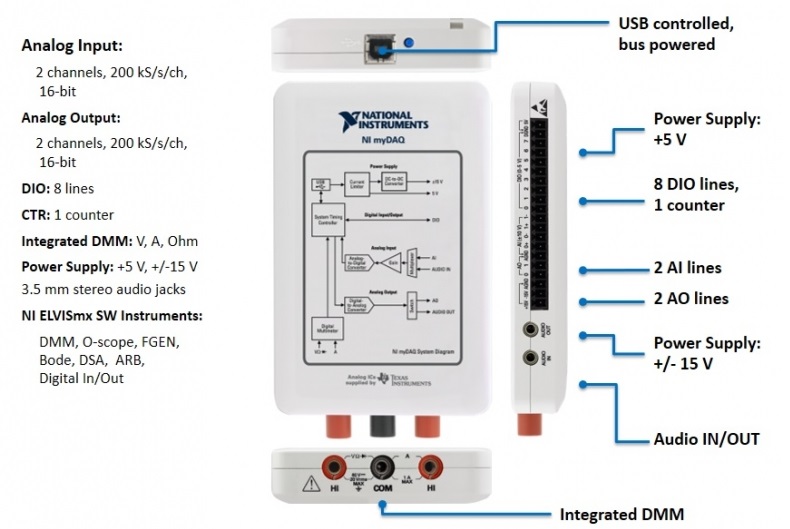
NI myDAQ is ideal for exploring electronics and taking sensor measurements.
NI myDAQ can be used with NI ELVISmx software front panels that turn NI myDAQ into eight different measurement and signal generation tools:
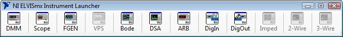
1- DMM (Digital Multimeter) 
The first important use of this device is digital multimeter which can measure voltage (DC and AC), current (DC and AC), resistance, diode test, and audible continuity measurements . the figure below is shown the front panel of NI ELVIS system max
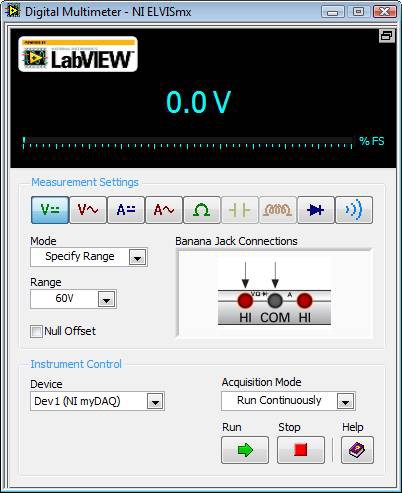
- the following ranges will be available for each instrument:
• DC Voltage: 60 V, 20 V, 2 V, and 200 mV
• AC Voltage: 20 V, 2 V, 200 mV
• DC Current: 1 A, 200 mA, 20 mA
• AC Current: 1 A, 200 mA, 20 mA
• Resistance: 20 M Ω, 2 M Ω, 200 k Ω, 20 k Ω, 2 k Ω, 200 Ω.
• Diode: 2 V range
• Continuity: Mode must stay in Au
2- Oscilloscope (Scope) 
This part can displays voltage data over time for the analysis of one or two voltage measurements taken from the analog input channels of the NI myDAQ.
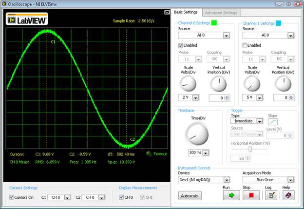
The available options when using a myDAQ are:
• Scale (Volts/Division): 5V, 2V, 1V, 500mV, 200mV, 100mV, 50mV, 20mV, and 10mV when using AI Channels
• 1V, 500mV, 200mV, 100mV, 50mV, 20mV, and 10mV when using AudioInput Channels
• Vertical Position (in Divisions): Variable by hundredths from -5 to 5 divisions.
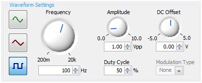
3 - Function Generator (FGEN) 
generates standard sine, square, and triangle waveforms and provides veries frequency, amplitude, DC offset, duty cycle, and modulation type adjustments.
4- Bode Analyzer (Bode) 
produces a Bode plot for signal analysis. The full-function Bode analyzer creates the plot by combining the frequency sweep feature of the function generator.
in addition of :
5- Dynamic Signal Analyzer (DSA) 
6- Arbitrary Waveform Generator (ARB) 
7- Digital Reader (DigIn) 
8- Digital Writer (DigOut) 
But Impedance Analyzer (Imped) , 2 Wire Current-Voltage Analyzer , 3-Wire Current-Voltage Analyzer (3-Wire) and variable power supply (VPS) are not supported by NI myDAQ and requires an NI ELVIS system


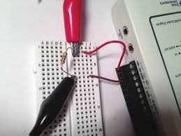
Experment : we can connect it with circuit via bread board to read volatage -current - analoge data ....
Individual assigment
Objective:
Redraw one of the echo hello-world boards or something equivalent, add (at least) a button and LED (with current-limiting resistor) or equivalent input and output, check the design rules, make it, test it.
First I have download the Eagle software cause this is my first time to use this software , I had designed my echo board with this several steps: with help of
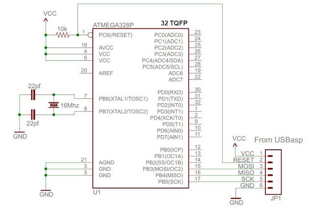
- I need to know the all component that I will used, but befor that I need to know What is the minimal set of parts for a circuit with this AVR atmega328p microcontroller?
With short search I get the circuit in figure below which describes the basic circuit
- Further than the basic connection I need use ISP (In System Programming )pins that allow microcontroller to be programmed in circuit as in figure below.
- Final, I need to digital and analog pins to use as inputs and outputs
Procedure::
1. Drawing the schematic in EAGLE Software:
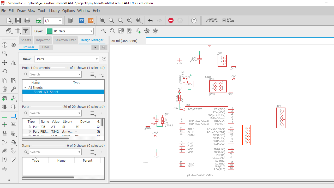
- Drawing the schematic I use EAGLE Software: EAGLE is an app for designing printed circuit boards. EAGLE is an acronym for "Easily Applicable Graphical Layout Editor." *first of all download Eagle Here create your project and follow these steps in figures below to draw the circuit schematic.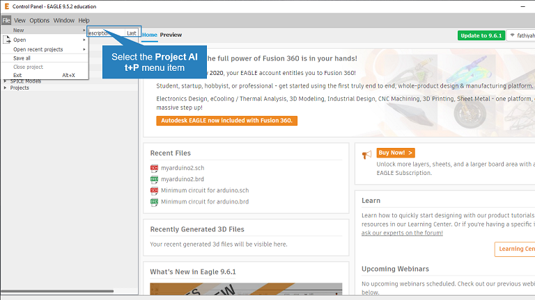
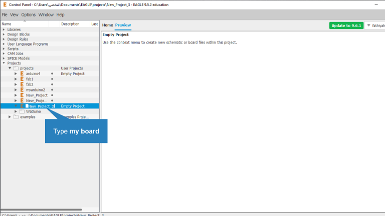
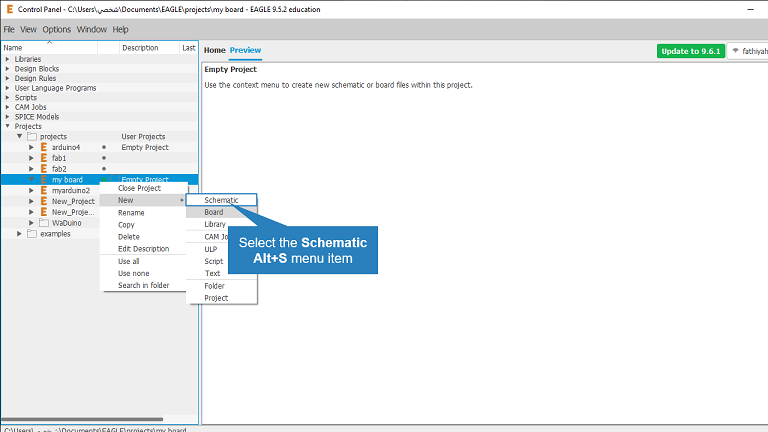
- Create a new project which I named --> my board then right click on my board --> new schematic then press CTRL+SHIFT+A to Add components.
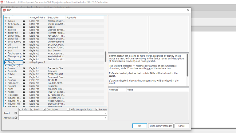
- choose the component in my ase I've added fab files which have our component, be sure you have added component with right package.
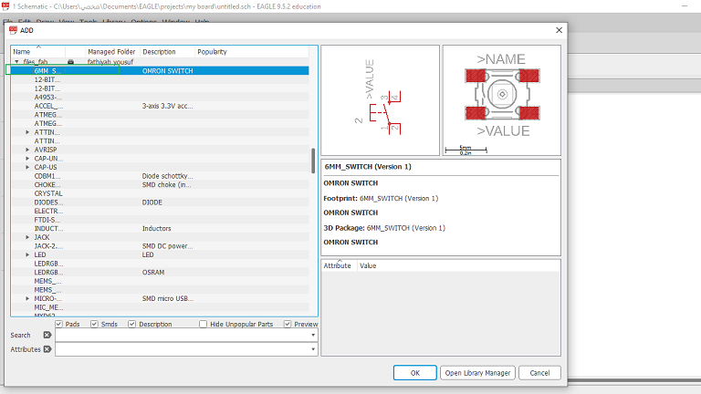
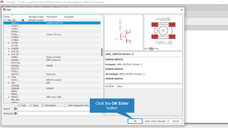
- To Add AVRISP double click to open the smd pakage.
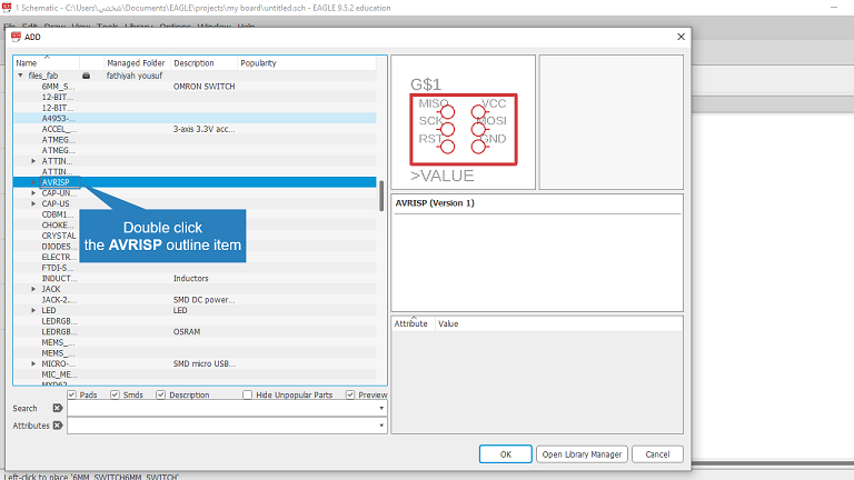
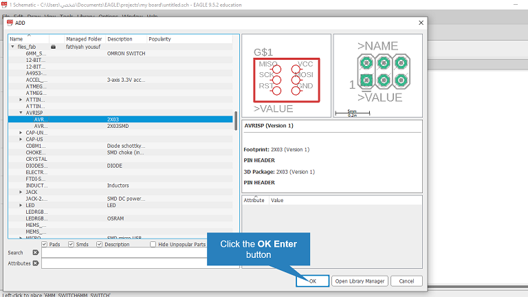
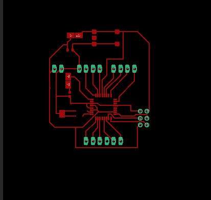
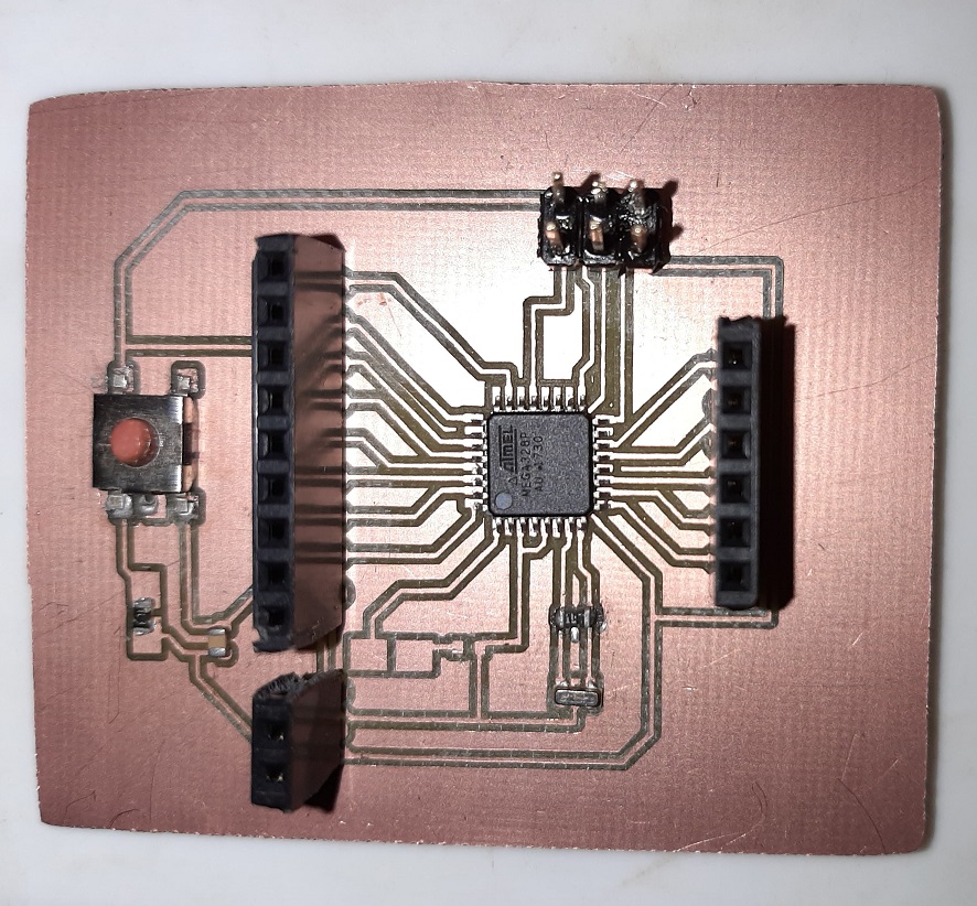
- with the same preview steps I've Added all the component as shown in figure below:
connect the Power of AVR microcontroller consists of two sections:
• Digital supply: (Pin 10 = VCC and Pin 11 = GND)Now, the schematic phase is completed and go the other phase (board)by click on board sample under schematic as figure, click Tool >> DRC to set the desing rules• Analog supply: (Pin 30 = AVCC and Pin 31 = AGND)
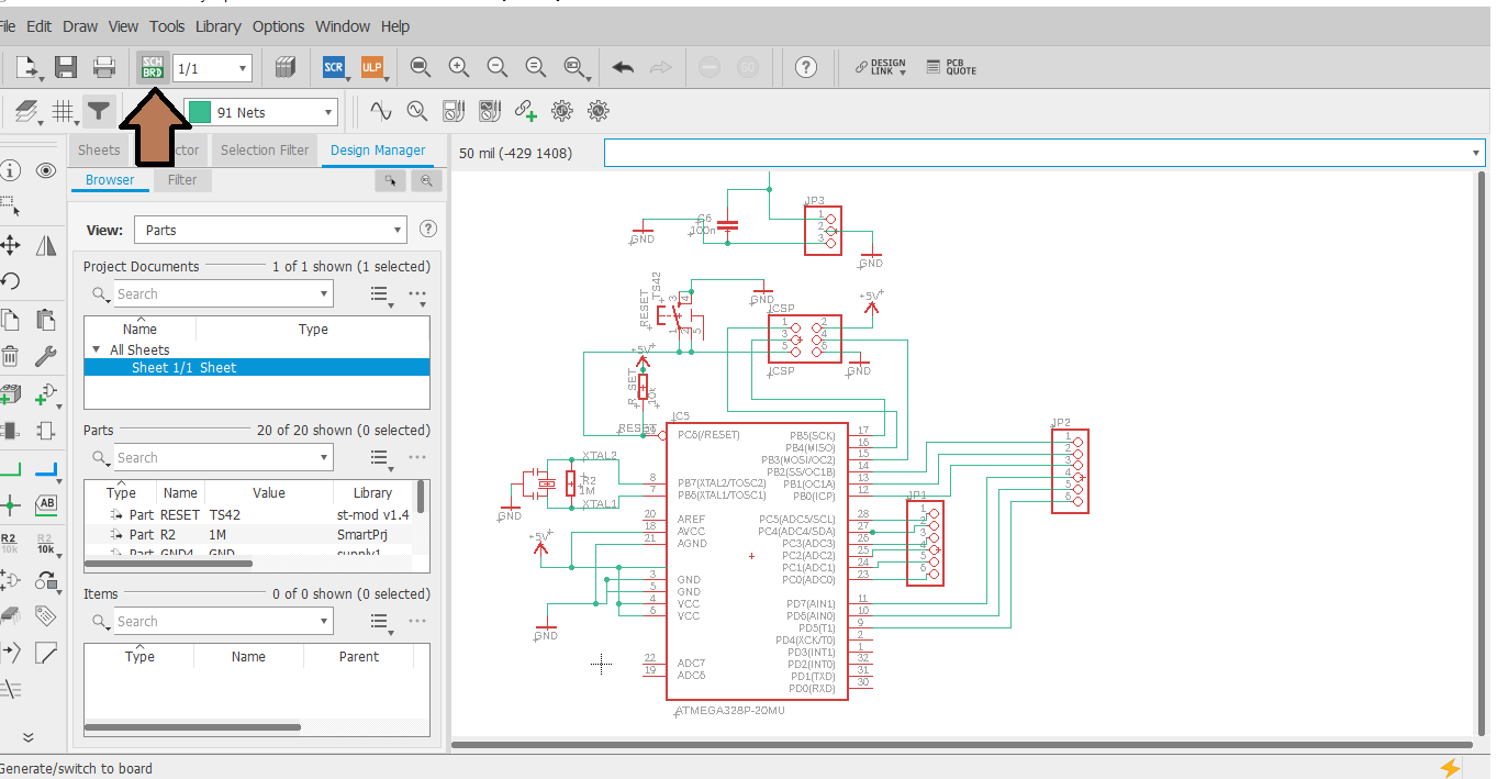
* connect each component with respective connector as shown circuit diagram
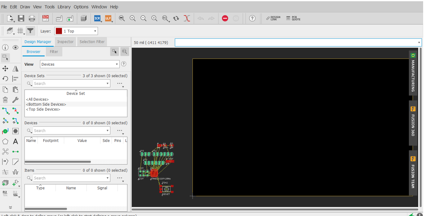
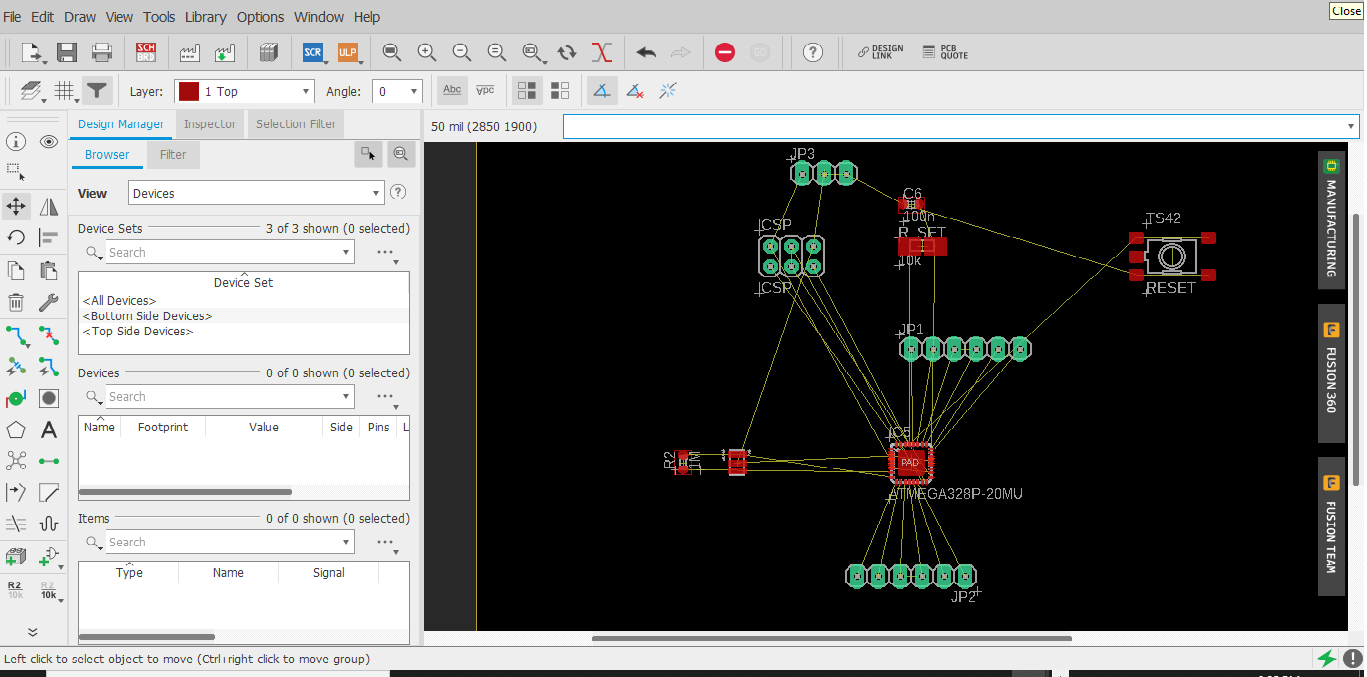
There is also an autorouter feature - it is good for making a general layout, but in my case it faild to trace my board, have to trace it manually.
To use the autorouter go to: the "tools" menu in the top toolbar and select "auto" you can also type "auto"
The component placement process is like a puzzle just waiting to be solved with your creative efforts.
2. Milling:
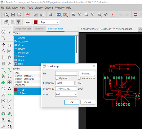
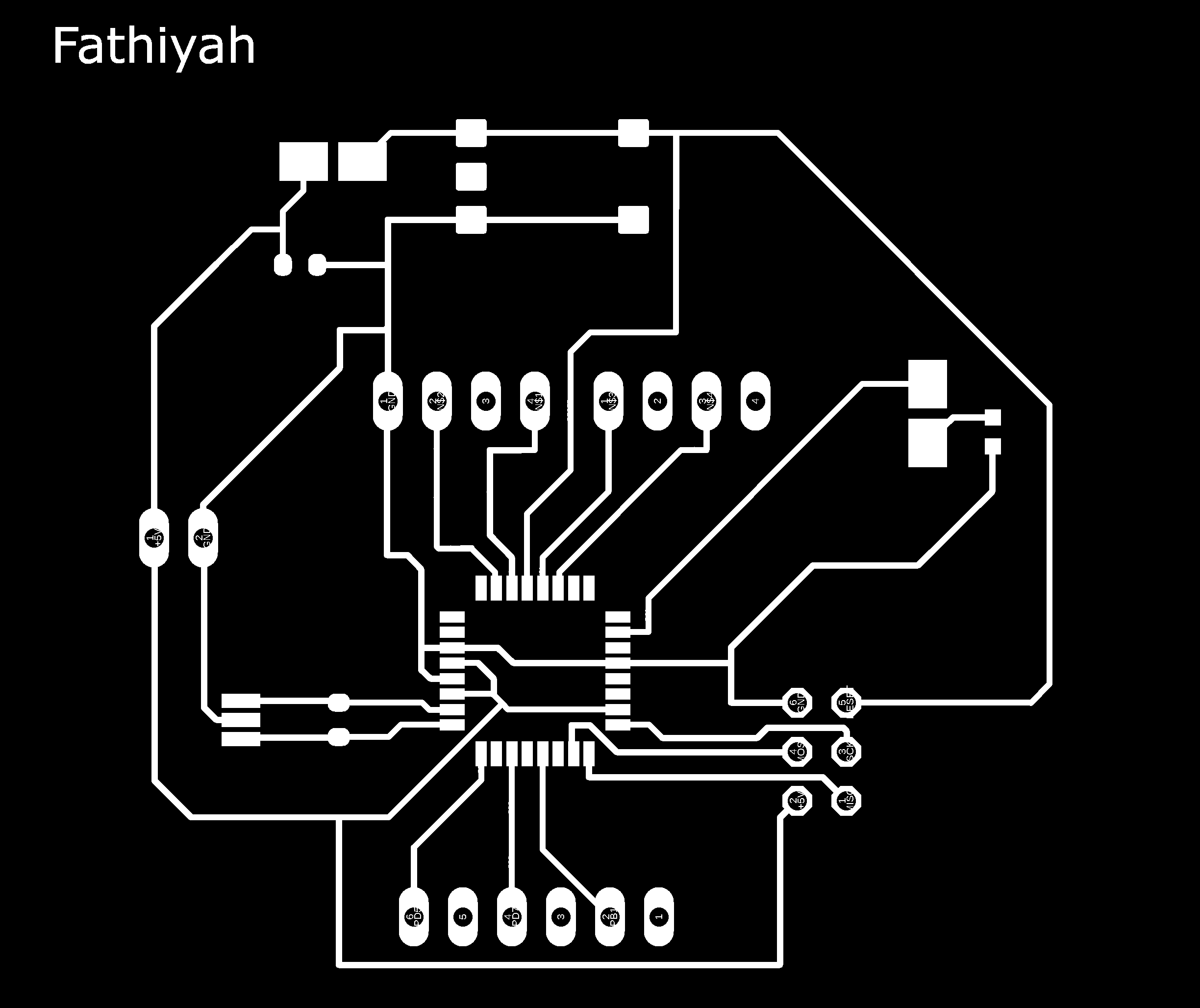
Then export as a png (file > export > image) and follow this tutorial to get black and whit diagram.
now we need gcode for router cnc machine, " FabModules" is a best open source methods it's easy and supporting with all machines, I've follow this tutorial
My Issue :
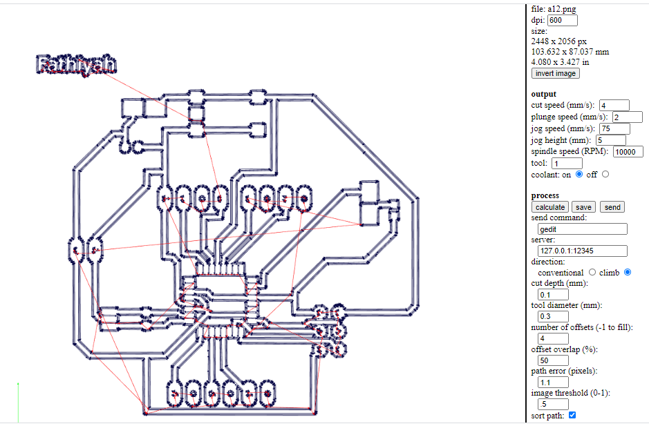
I had a problem during trace which the microcontrollers pins didn't trace well,there are connection between every two pins. this issue shows in diagram below. I solved this problem by change tool diameter (mm) from 0.4 to : 0.3 .
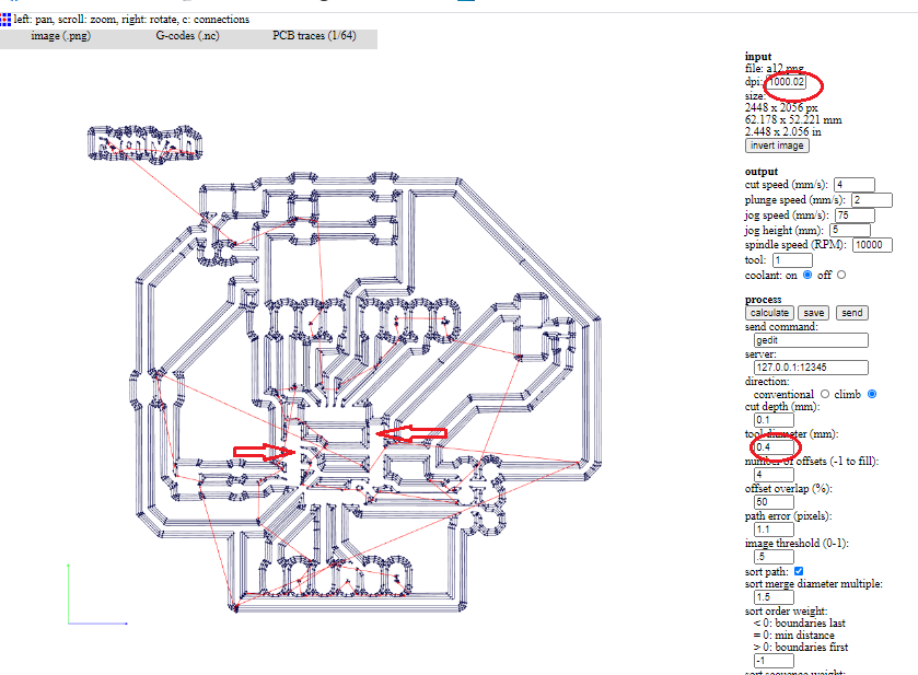
after that I descovered other error that when I exported "my board" image with (600dpi) resolution - at eagle software- but wwhen I imported in MODs I didn't changed the defult that (1000) this issue change the circuit dimention. Now, the output gcode that generated by MODs will send to Mach3 software for cnc router.
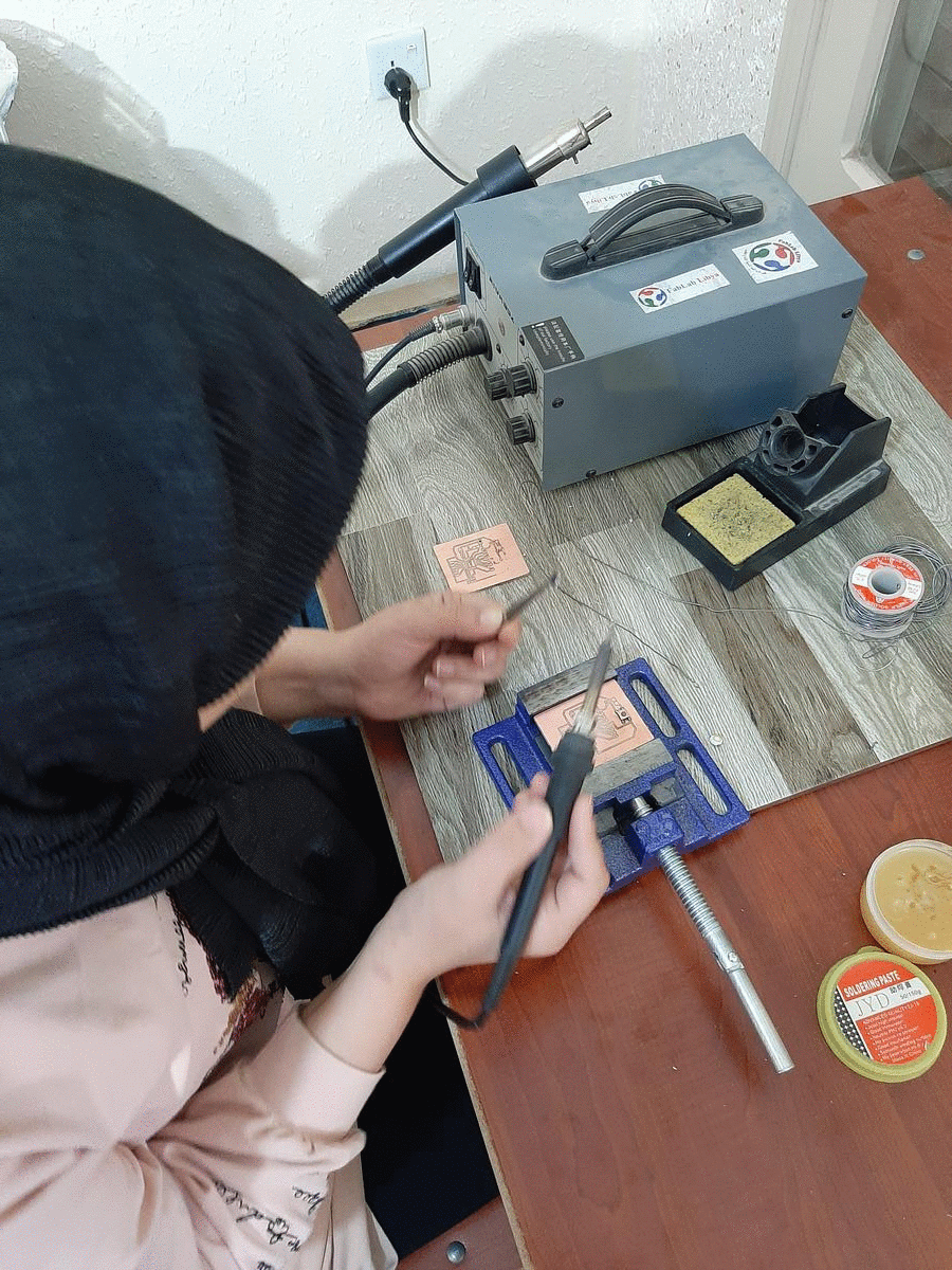
3. Soldering
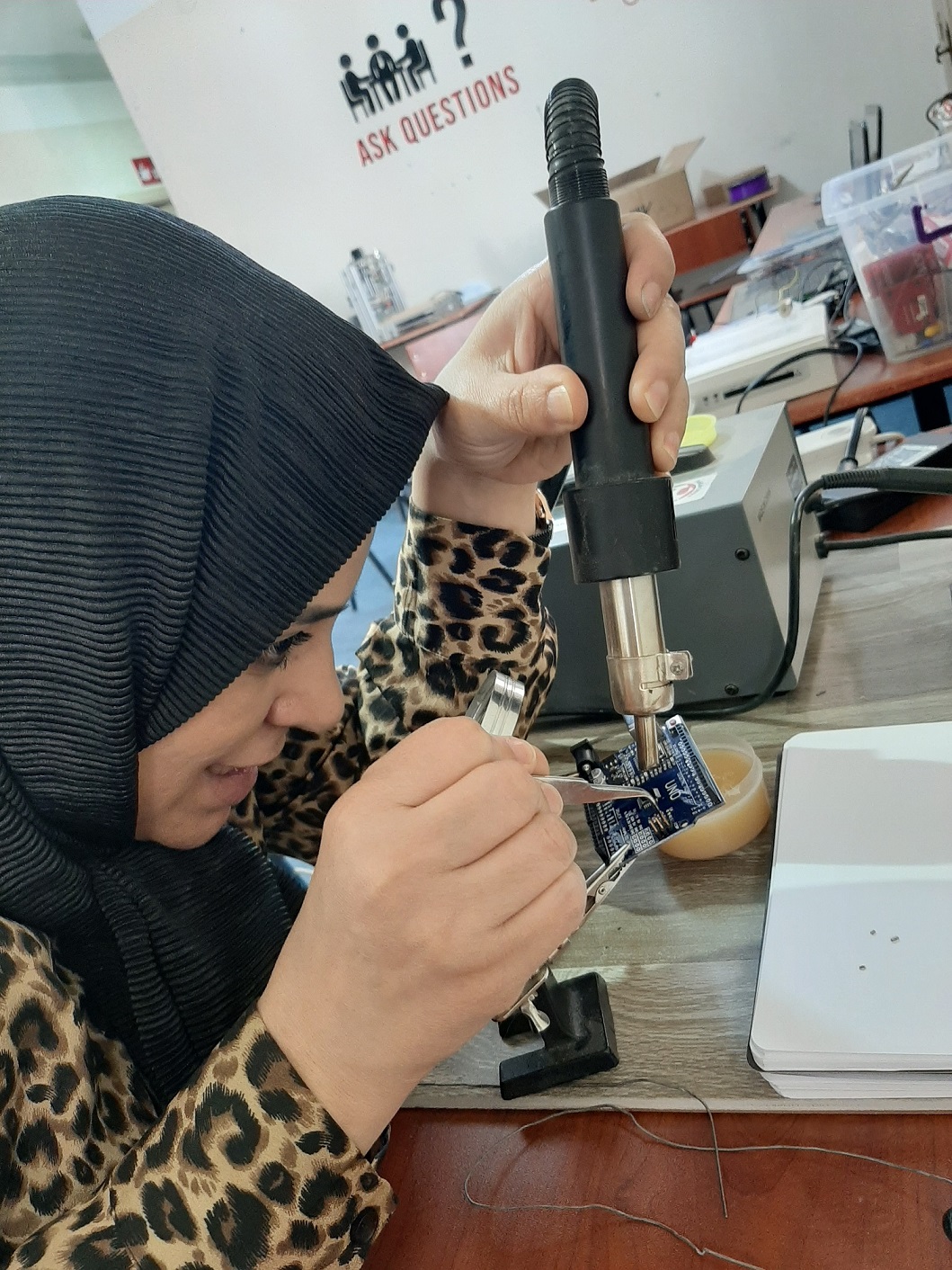
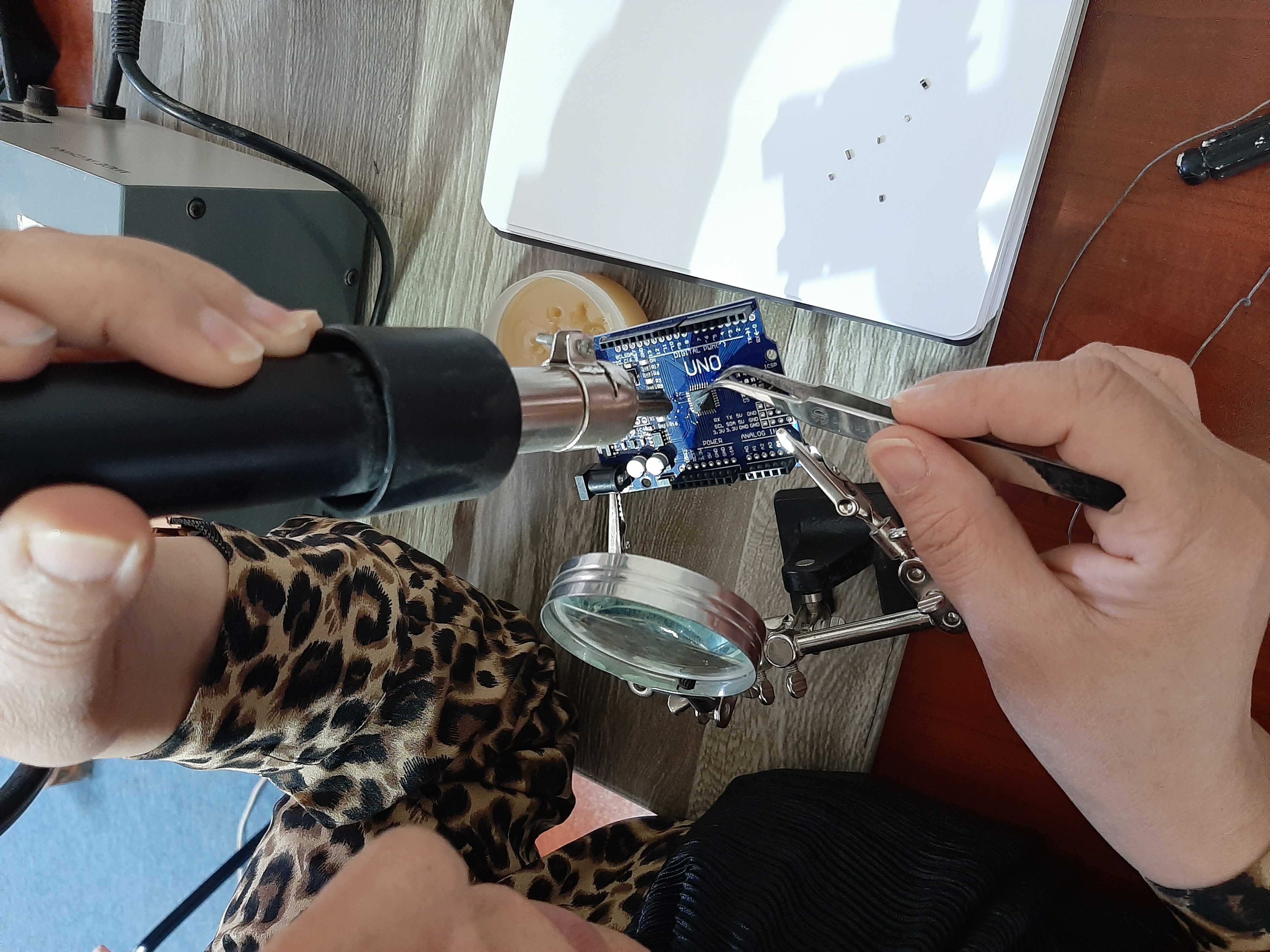
As COVID19 affect, the complete quarantine took place this week in my country, which makes it difficult to go to the lab ,as all shipping companies canceled shipping operations to us, and I was in the process of receiving a shipment of electronics from DigKey that I will need for my project and to carry out the tasks of these week.
However, I decided to address these limitations and find alternatives, That made me taking apart an Arduino Board by desoldering to get components, so that I could re-solder them in my own board
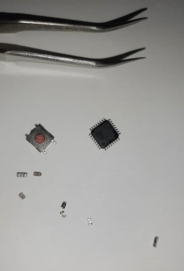
Finally I have my SMD components, I hope this electronics work!
resolding component to my board then tested the soldering by digital multimeter
4. Programming
To programming Myboard I used arduino as progammer these step you can find it in Embedded progamming week but in this week I've download "blink " from arduino example