Output Device
In this assigment I have tested my board with multi output devices: RGB led, LCD (as in my final project) and servo motor. which I've test in group assigment.
Group Assigment
I've to test servo motor power consumption, in this case I powered the servo motor from power supply and read the following current, servo motor needs pulse width modulation signal (PWM)that i feed it from arduino.
From this experment we get current flowing range (12-16)mA at 5V voltage supply
In this experiment a potentiometer is used to control the degree of servo motor, servo motor is rotate according to potentiometr rotation.
The arduino code with describtion are here below:#include
Servo myservo; // create servo object to control a servo int potpin = 0; // analog pin used to connect the potentiometer int val; // variable to read the value from the analog pin void setup() { myservo.attach(11); // attaches the servo on pin 9 to the servo object } void loop() { val = analogRead(potpin); // reads the value of the potentiometer (value between 0 and 1023) val = map(val, 0, 1023, 0, 180); // scale it to use it with the servo (value between 0 and 180) myservo.write(val); // sets the servo position according to the scaled value delay(15); // waits for the servo to get there (depending o servo speed) }
Individual Assigment
1- Output Device with my own board.
In this part I've used RGB as output device as indicator or alarm which light red when the amount of sensor read is increased and light Blue if this amount is low, but first we need to know what is RGB?
RGB LED: is respective to Red-Green-Blue light emitter diode that means RGB works s 3 different colors LEDs
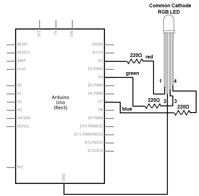
Figure below describe How to connect RGB with arduino,this connect like 3 leds with one common.
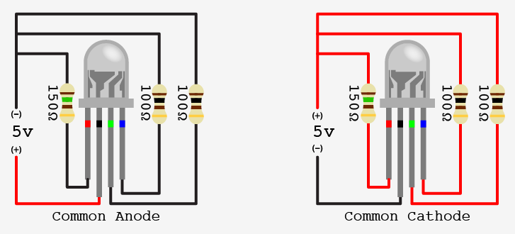
To get variable output from my board I connected RGB leg with PWM(pulse width modulation) pins here I used pin13,14,15 in Atmega IC that named to PB1,PB2,PB3 and respect to 9,10,11 in Arduino code, Note that I used power supply model that connected to computer USB to get 5V supply.
In this task I used potentiometer to give the amount of sensor and work as an input, then use map function to convert from 1023 (analoge read value) to 255 PWM range (RGB color range). the arduino code with describtion are here below:
int potpin = 0;    // potentiometer value
int val,val1,val2,val3;

void setup() {
  pinMode(9,OUTPUT);     //RGB  pin1
  pinMode(10,OUTPUT);    //RGB  pin2
  pinMode(11,OUTPUT);   //RGB  pin3
}
void loop() {
  val = analogRead(potpin);            // reads the value of the potentiometer (value between 0 and 1023)
  val1 = map(val, 0, 1023, 0, 255);     // scale it to use it with the LED (value between 0 and 255)
  val2 = map(val, 0, 1023, 255, 0);
  val3 = map(val, 0, 1023, 0, 200);
  analogWrite(9, val1 );
  analogWrite(10, val2 );
  analogWrite(11, val3 );
 }
2- Arduino and 16x2 LCD display screen with I2C interface
In this section I have tested the LCD to display the solar cells voltage out. I've divided this task to four main steps
a - Arduino coding
b - Project simulation with (protuse software)
c - Implementation with Arduino
d - Output Device with my own board
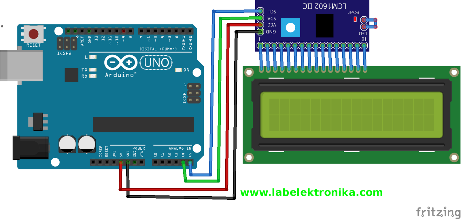
It is able to display 16x2 characters on 2 lines, white characters on blue background. This I2C 16x2 Arduino LCD Screen is using an I2C communication interface. It means it only needs 4 pins for the LCD display: VCC, GND, SDA, SCL. It will saves at least 4 digital / analog pins on Arduino. All connector are standard XH2.54 (Breadboard type). You can connect with jumper wire directly.
a- Arduino Coding steps:
- Firstly we start with Initialization stage which have Initialize the LCD by add the lcd library with code:
    *  #include Wire.h>
    *  #include LiquidCrystal_I2C.h
2- Second, we need to read Analoge value from solar cell as an input and print it to LCD here is the code
b - Project simulation (Protuse software)
protuse software allow you to Design, Test and Debug complete embedded systems inside Proteus schematic capture before ordering a physical prototype. Proteus VSM brings AGILE development to the embedded workflow.
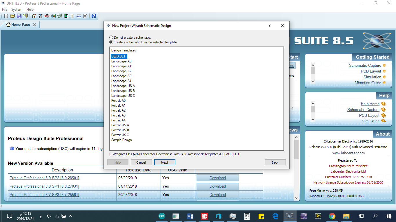
- Here is the steps to create your project: open new project and named it, choose Defulat in new project Wizard: schematic design.
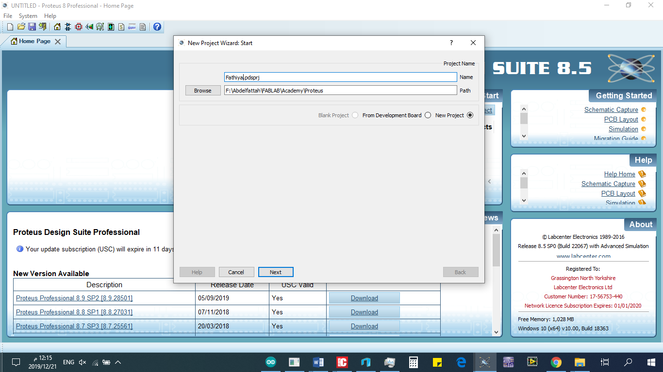
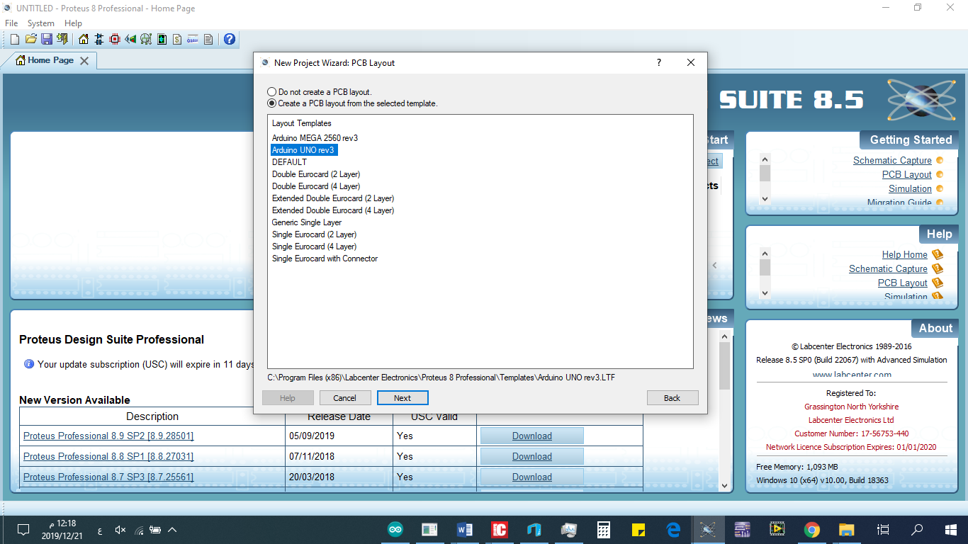
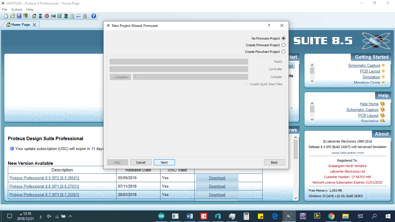
- click --> next will open new project Wizard:PCB Layout in this case you will choose Arduino UNO, then click next which open new project Wizard:Firmware in this case chooe NO projet firmware project.
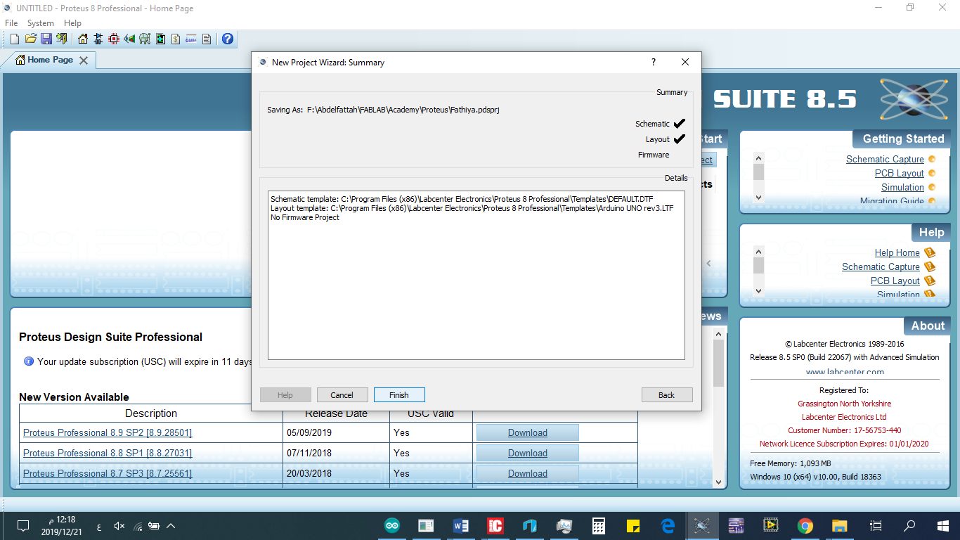
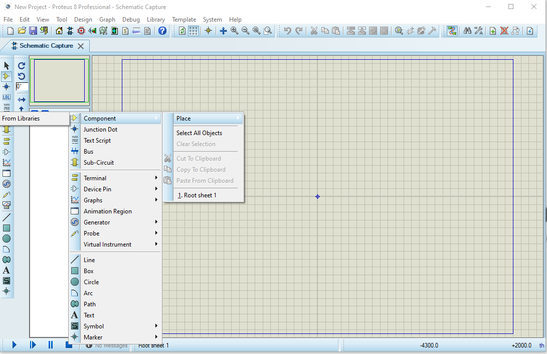
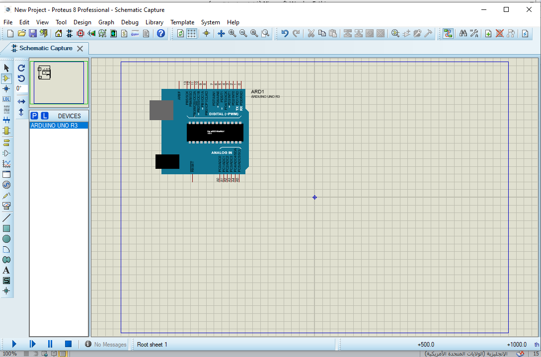
- Then finished wizard window will appear click--> finish, the shmetic capture will open click to "P" to place the component.
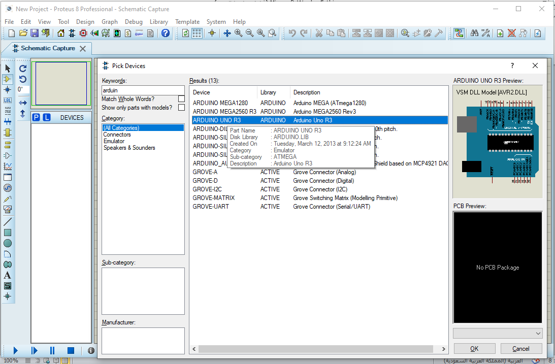
- In kerword write arduino choose ARDUINO UNO R3 click--> OK, with the same steps choose LCD and LDR.
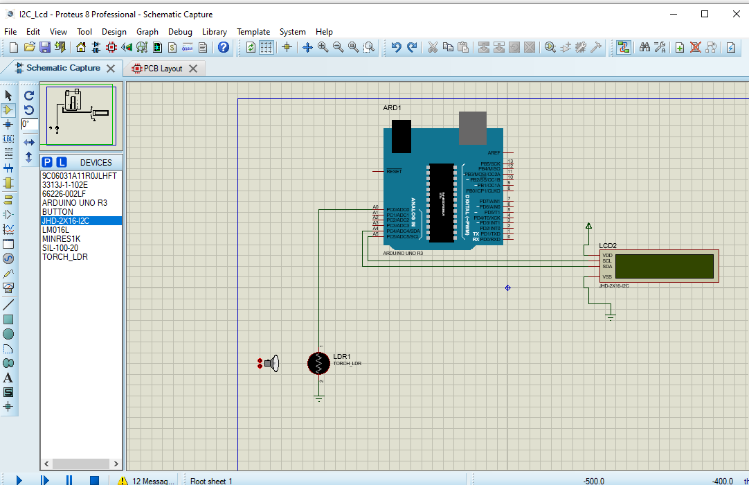
Now, we need draw the circuit by connect the circuit as bellow
Go the direct that have saved the hex file of arduino code and import them to protuse
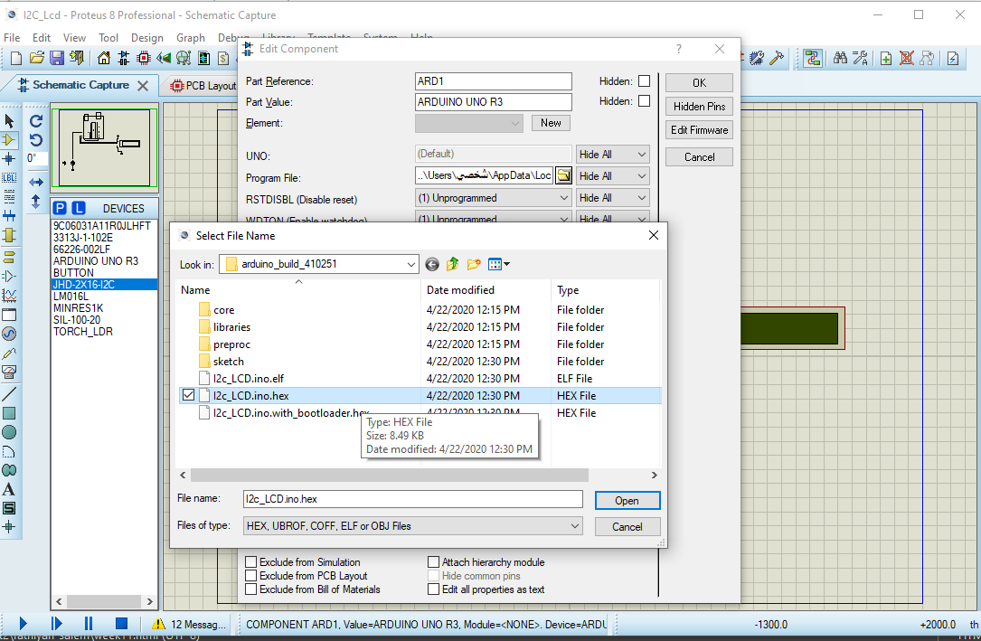
Finaly, you can press Run button in protuse to simulate your project
c- Implementation
To implemente we need connect: the positive of solar cell with A0 of arduino and the negative with GND, and coect the SDL pin of LCD with A5 ad SDA pin of LCD with A6 and feed LCD with VCC and GND.
WIRING DIAGRAM