Computer Aided Design
Computer-Aided Design (CAD) is technology for design and technical documentation, which replaces manual drafting with an automated process. If you're a designer, drafter, architect, or engineer, you've probably used 2D or 3D CAD programs open source such as *
Blender - BricsCAD Shape, BRL-CAD -FreeCAD
LibreCAD - OpenSCAD , QCAD - SolveSpace
Tinkercad software.
 and Commerical*
ActCAD - Alibre Design -Autodesk Inventor , AxSTREAM - BricsCAD - CATIA
Cobalt - Fusion 360 - IntelliCAD,IRONCAD - KeyCreator  - MEDUSA
MicroStation - Modelur - Onshape ,Promine - PTC Creo -VariCAD
PunchCAD- Remo 3D - Rhinoceros 3D, RoutCad- Siemens NX - SketchUp
Solid Edge - SolidWorks - SpaceClaim, T-FLEX CAD - TurboCAD
This week I've tried two softwares to draw gears I have used inkscape and FreeCad Inkscape is more easy then FreeCad but FreeCad is 3D designner but inkscape 2D
This tutorial helps me to start Inkscap Tutorial When I researched "How to draw Gear", I found two methods :
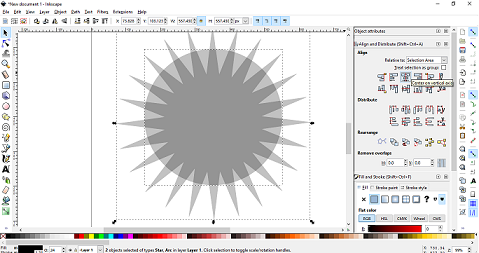
1- First method describes how to draw gear from scratch, I have draw star and circle.
select both of them and align by --> center in vertical axis and center in horizontal axis -->
Select both of circle and star then click difference from path
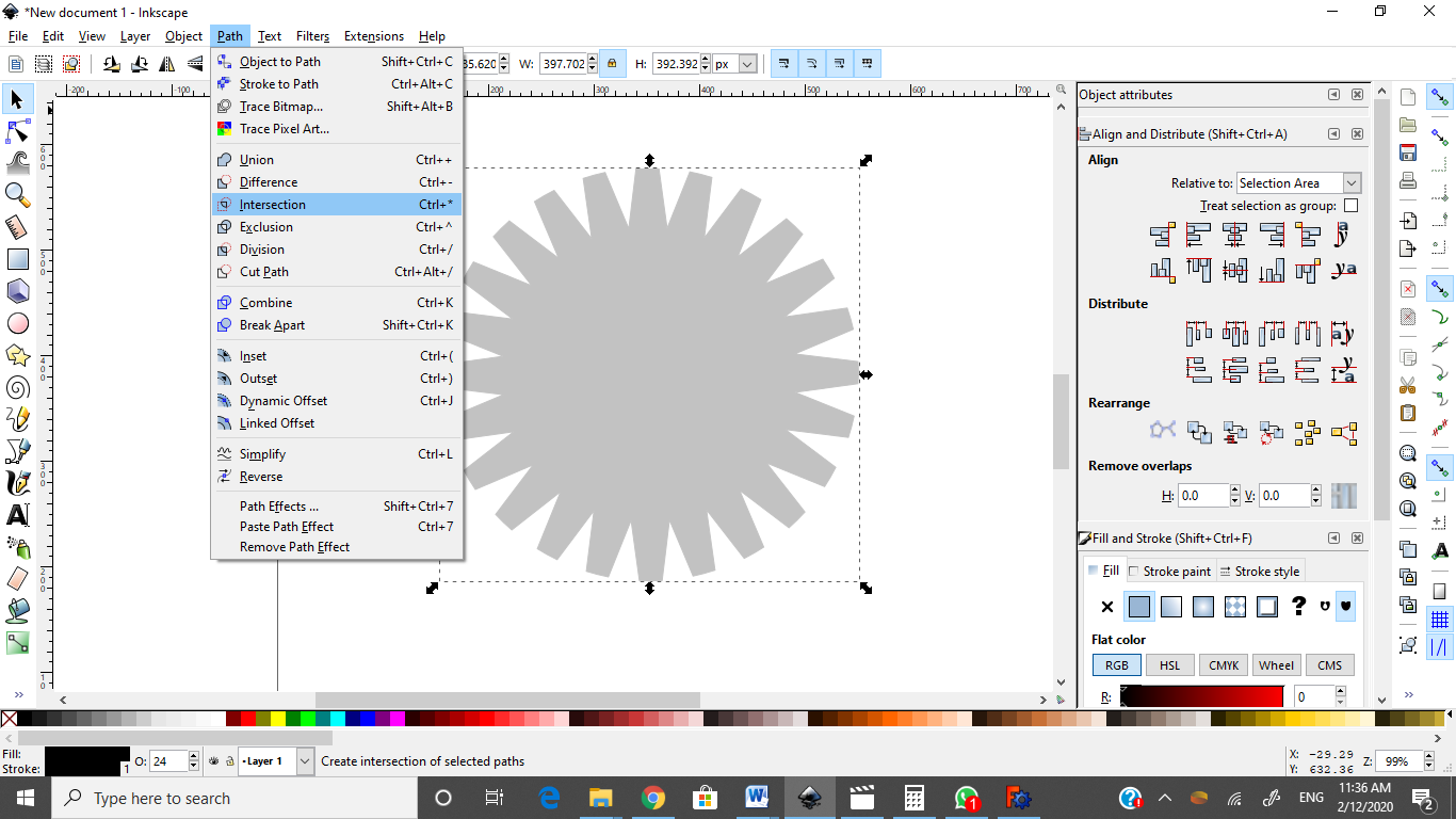
Draw another circle bigger the first one and select two objects and applied intersection
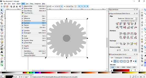
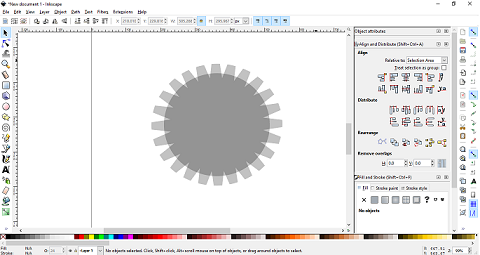
Draw small cicle and applied Exclusive then will get 2D gear
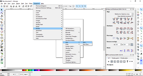
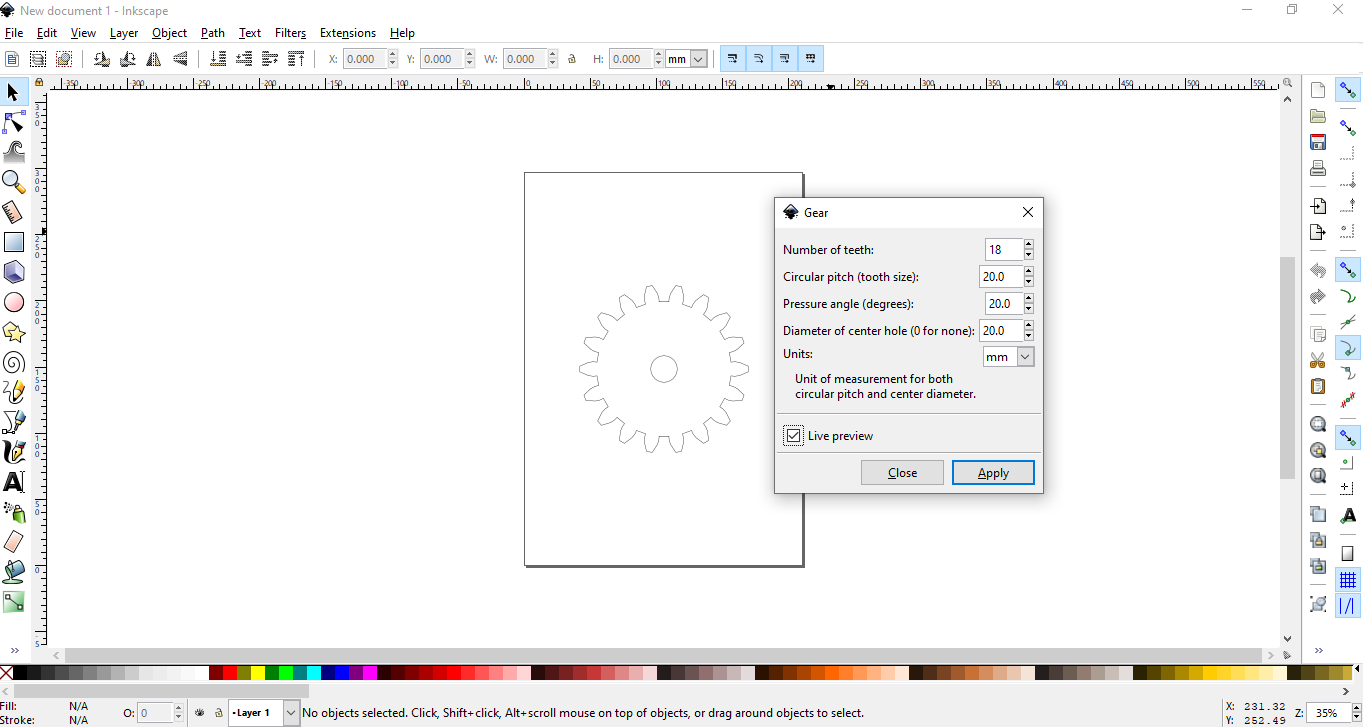
2- Second method is an option in inkscap Extenasions ----> Render---> Gear like figure bellow
To simulate two gear you can follow this vedio:
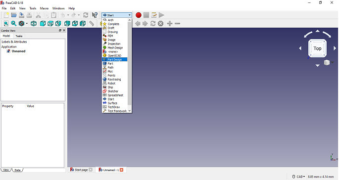
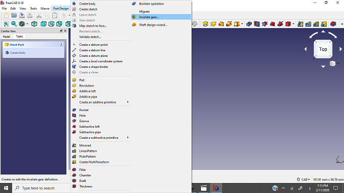
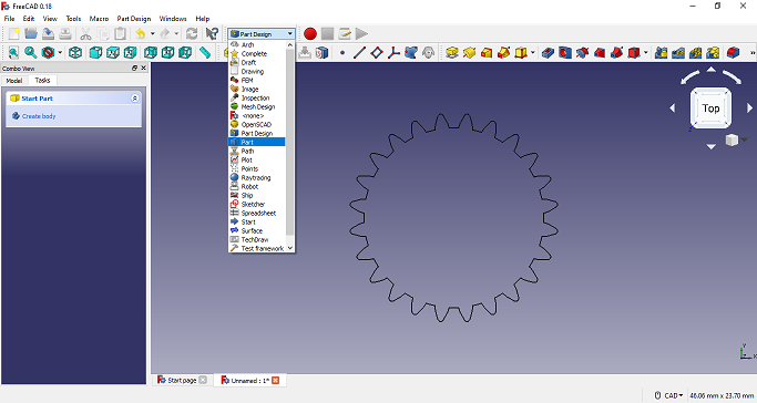
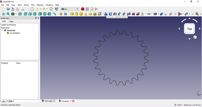
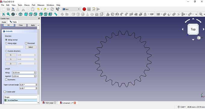
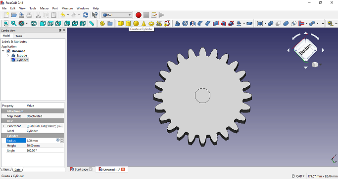
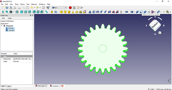
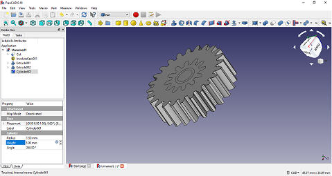
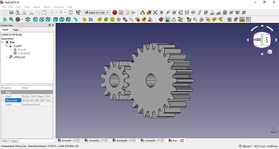
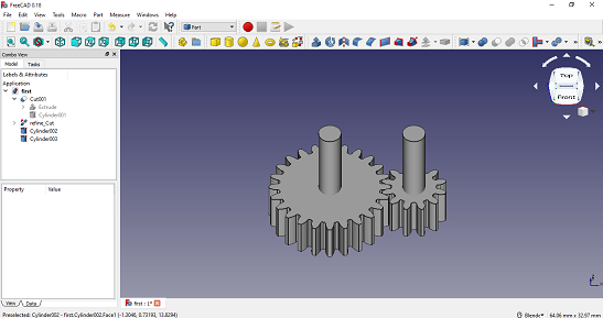
To Draw 3D Gear you here interested vedio I have follow him and get my 3d gear
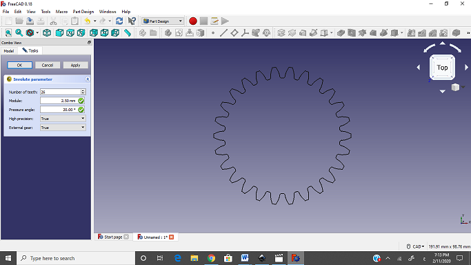
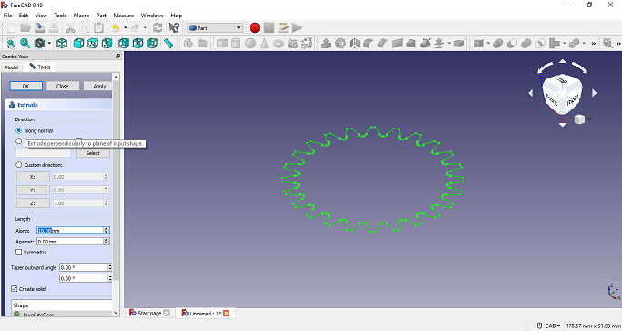
Note that to change position you must use this equations
M*((T1+T2))/2
Where M=15/24=0.62
T1=24
T2=12
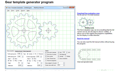
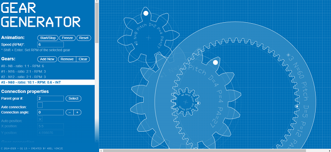
I need To Design and simulate Gear ratios and compound gear ratios, to use this design in my final project, after research I found these Useful websites:
** Gear ratios and compound gear ratios website
** Gear Generator website
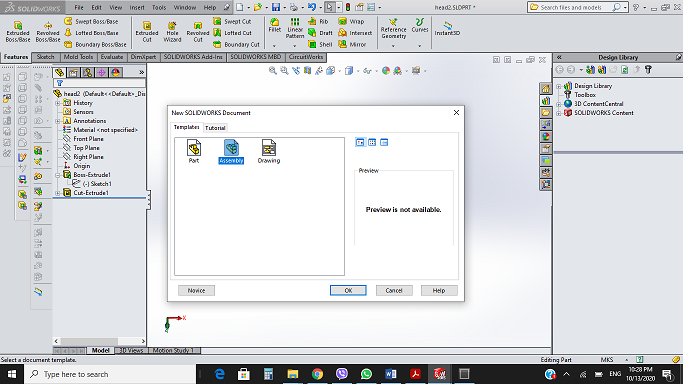
SolidWorks software
SOLIDWORKS is used to develop mechatronics systems from beginning to end. At the initial stage, the software is used for planning, visual ideation, modeling, feasibility assessment, prototyping, and project management. The software is then used for design and building of mechanical, electrical, and software elements.
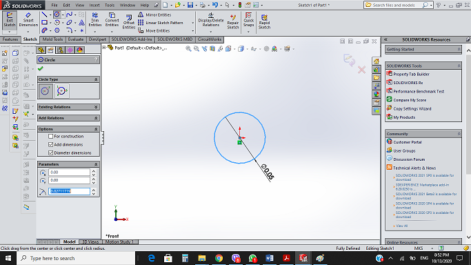
* To create new sketch by right click on the plane that you will draw at it.
* chosse circle from sketch tool and draw circle, from the same center draw the secand circle.
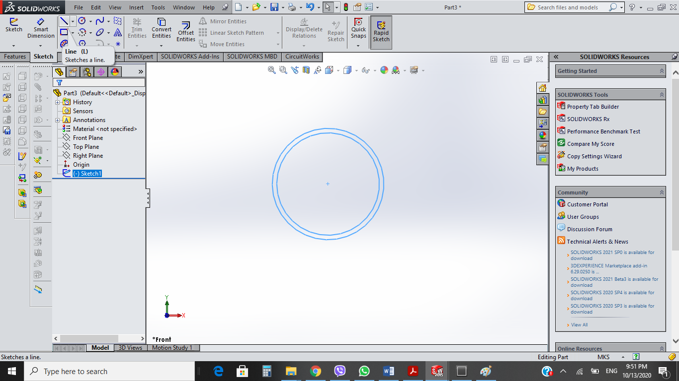
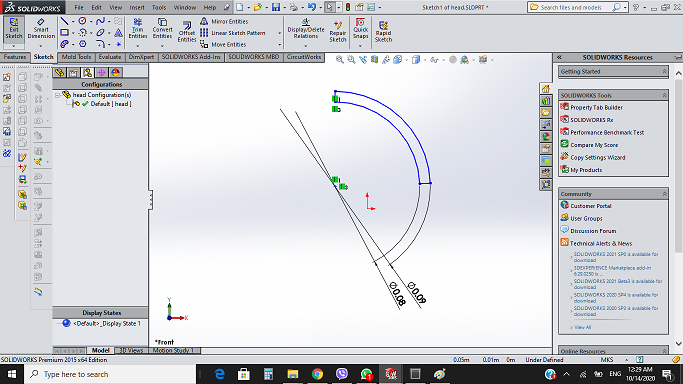
* Draw two circles with a line intersecting it directly through the centre point and line intersection a half circle.
* Trim the 3/4 circle away, leaving the quarter of two circle with line connection betwee them.
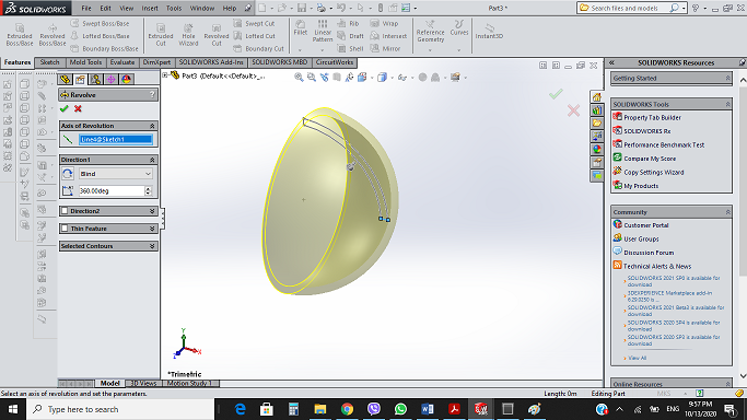
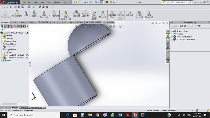
* Create a Revolve Boss/Base in (Features) tool bar.
* To make 3D we need to go to another tab and Revolve Boss.
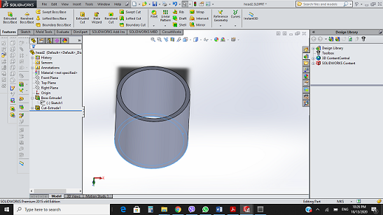
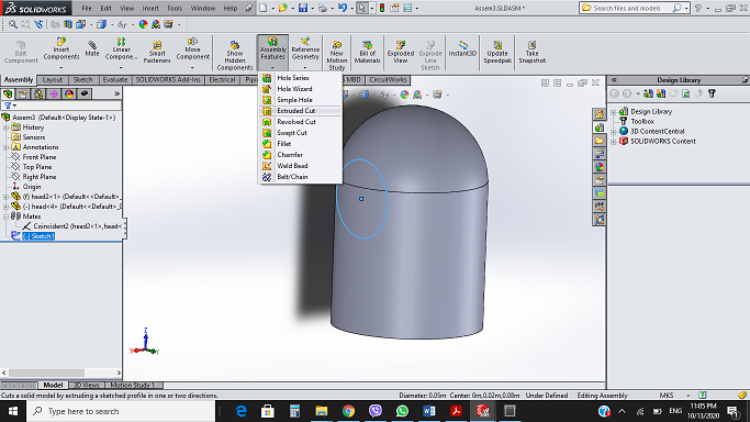
* craete new part with the same two circles but this time choose Extruded Boss/Base with outer circle.
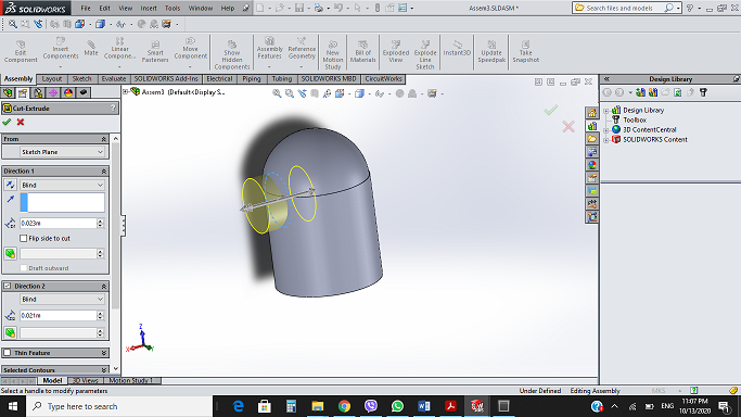
* choose the inner circle apply the Extruded cut to get cylinder.
* Insert the two parts by add components compoenets and select two parts
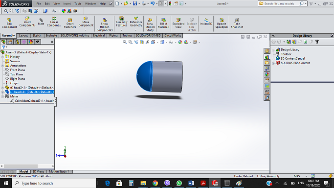
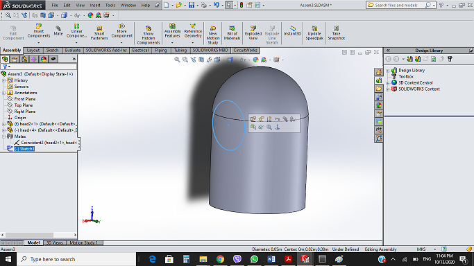
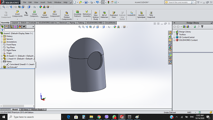
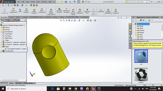
*when i have finished my design I want to change the material of my design by right click on Material and choose yellow color as show figure below.
* In solid work I could touch the features of parameteric design, I can change any dimenstion at any time throw the design, smart dimention tool is realy very useful.
Cad Files: