15. Netwoking and communication
This week’s task was to design and build a wired or wireless network connecting at least 2 processors
Group Assignment:
- Send a message between two projects
Individual Assignment:
- Read a microcontroller data sheet. Program your board to do something, with as many different programming languages and programming environments as possible
Group assignment
To check how we Sended a message between two projects
Click on this link
Networking
In embedded system all about interlinking circuits(Microcontrollers,Sensors,Actuators,networks etc) to create a complete system .in many situations for swaping informations from one circuit to another they must have a common communication protocol ,lot of communication protocols available they all underlying two main catagories serial and Parallel .
serial communication
is the process of sending data one bit at a time, sequentially,over a communication channel. It uses two wires to implement an asynchronous full duplex communication, but only between two devices.
Networking SPI
The SPI (Serial Peripheral Interface) bus is a synchronous full duplex master-slave serial communication interface specification used for short distance communication, primarily in embedded systems. It requires up to four wires allowing full duplex communication for a with a single slave.
Networking I²C
I²C, pronounced I-squared-C, is a multi-master, multi-slave, serial computer bus invented by Philips Semiconductor. It supports several slaves (eg 100+) allowing one transmission per time between the master and one slave. The transmission is not full duplex.
Networking Wifi
Wi-Fi is a wireless networking technology that allows computers and other devices to communicate over a wireless signal. It describes network components that are based on one of the 802.11 standards developed by the IEEE and adopted by the Wi-Fi Alliance.
Networking Bleutooth
Bluetooth is a wireless technology standard for exchanging data over short distances from fixed and mobile devices, and building personal area networks (PANs). Bluetooth Low Energy is a wireless personal area network technology designed and marketed by the Bluetooth Special Interest Group aimed at novel applications in the healthcare, fitness, beacons, security, and home entertainment industries. Compared to Bluetooth, Bluetooth Low Energy is intended to provide considerably reduced power consumption and cost while maintaining a similar communication range.
Individual assignment
To be honest, I had no previous background around Networking. So I had to start from the very begining and understand what is networking and what’s is serial commnications. First i tried serial communication between 2 arduinos
The basic idea for this is to communicate 2 arduino board through communicating TX, RX and GND pins, send a character through the first board “Master”, receive it through the second board “Slave” and flash the LED.
This is how you communicate the 2 arduino boards
.
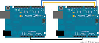
The TX goes to RX and RX goes to TX, also there has to be a common ground between the two or else it will not function properly.
Programming
For Master board I used the following code to sent “H” to turn on the Slave board’s led for 1 sec , and sent “L” to turn off the Slave board’s led for 1 sec
                  //Master
                void setup() {
                Serial.begin(9600);
                }
                void loop() {
                Serial.print('H');
                delay(1000);
                Serial.print('L');
                delay(1000);
                }
For Slave board I used this Example to obtain the information from the serial port and turns on the LED if it gets “H”, and turns it off if it is “L”.
This example code is in the public domain. Check this link
               const int ledPin = 13; // the pin that the LED is attached to
                int incomingByte;      // a variable to read incoming serial data into

                void setup() {
                  // initialize serial communication:
                  Serial.begin(9600);
                  // initialize the LED pin as an output:
                  pinMode(ledPin, OUTPUT);
                }

                void loop() {
                  // see if there's incoming serial data:
                  if (Serial.available() > 0) {
                    // read the oldest byte in the serial buffer:
                    incomingByte = Serial.read();
                    // if it's a capital H (ASCII 72), turn on the LED:
                    if (incomingByte == 'H') {
                      digitalWrite(ledPin, HIGH);
                    }
                    // if it's an L (ASCII 76) turn off the LED:
                    if (incomingByte == 'L') {
                      digitalWrite(ledPin, LOW);
                    }
                  }
                }
Unfortunatelly because of the corona virus , i still not able to acees the fab lab and to use arduino that’s why i tried a tinkercad simulation as showing bellow
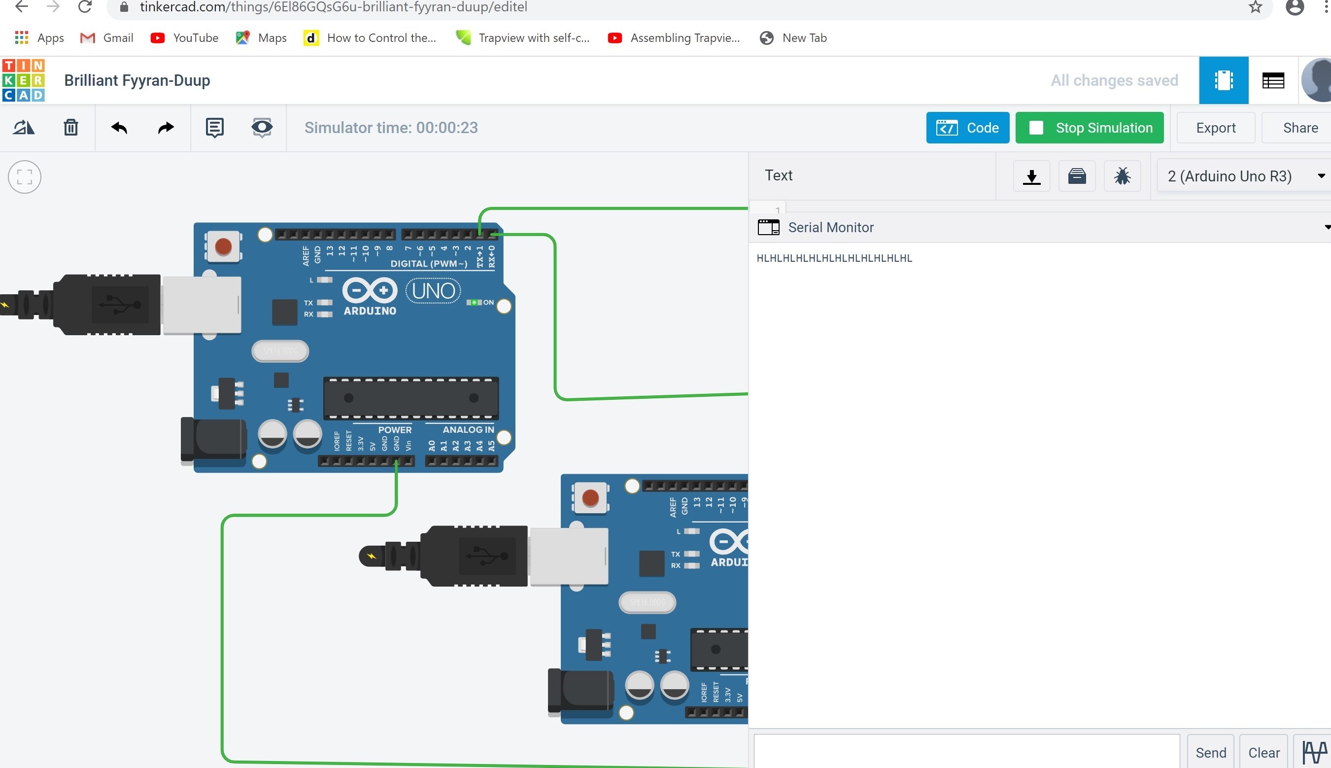
Now i become able to use the arduino for simulation
so i connected the two arduinos as mentioned before and the code run well

I2C Communications
I2C is a serial protocol used on a low-speed 2-wire interface. It was originally developed by Phillips in 1982 to allow integrated circuits within television receivers to communicate with one another. I2C is an abbreviation for “Inter-Integrated Circuit”. It is also called “IIC” or ‘I squared C”.
Uses and Limitations
I2C is used with microcontrollers like the Arduino and with microcomputers like the Raspberry Pi. Many displays and sensors interface to their host controller using I2C.
I2C does have several limitations however. It is not particularly fast, although for most of its intended uses it is plenty fast enough.
I2C can only be used over short distances, after all, it was originally meant to communicate between integrated circuits on the same printed circuit board. The maximum distance of reliable transmission decreases as the speed increases, at the slowest speed (100 Kbaud or a clock rate of 100 KHz) the maximum distance is about a metre.
I2C Speeds
The original I2C bus had a maximum speed of 100 KHz. Most common applications still use this speed, as it is quite sufficient for transferring data from sensors and to simple displays.
I2C and has some higher speed modes. Not all I2C devices support these modes:
Fast Mode – This has a maximum clock speed of 400 KHz. Hi-Speed Mode – A maximum clock frequency fo 3.4 MHz Ultra Fast Mode – Maximum clock frequency of 5 MHz
How I2C Works
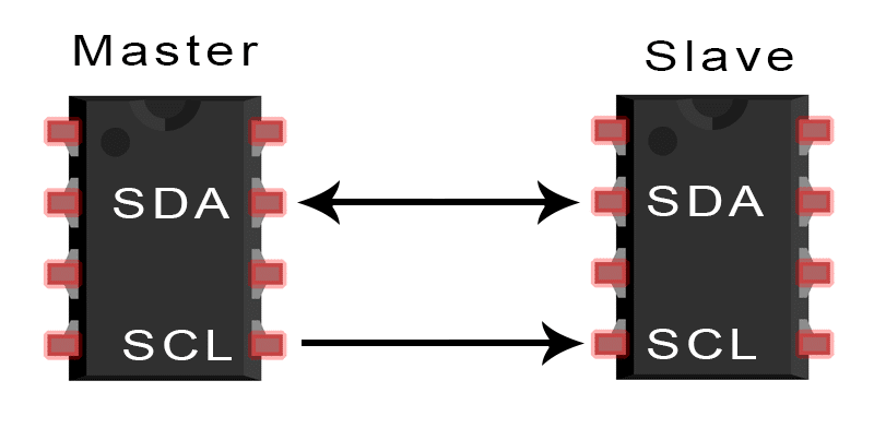
An I2C bus has two signals, along with a power and ground connection.
The two signal lines are as follows:
SDA This is the bidirectional data line. SCL This is the clock signal.
To demonstrate the I2c protocol i m going to use a potentiometer to the master board and an LED to the slave.
the potentiometer is to control the blink rate of the LED.
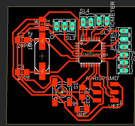
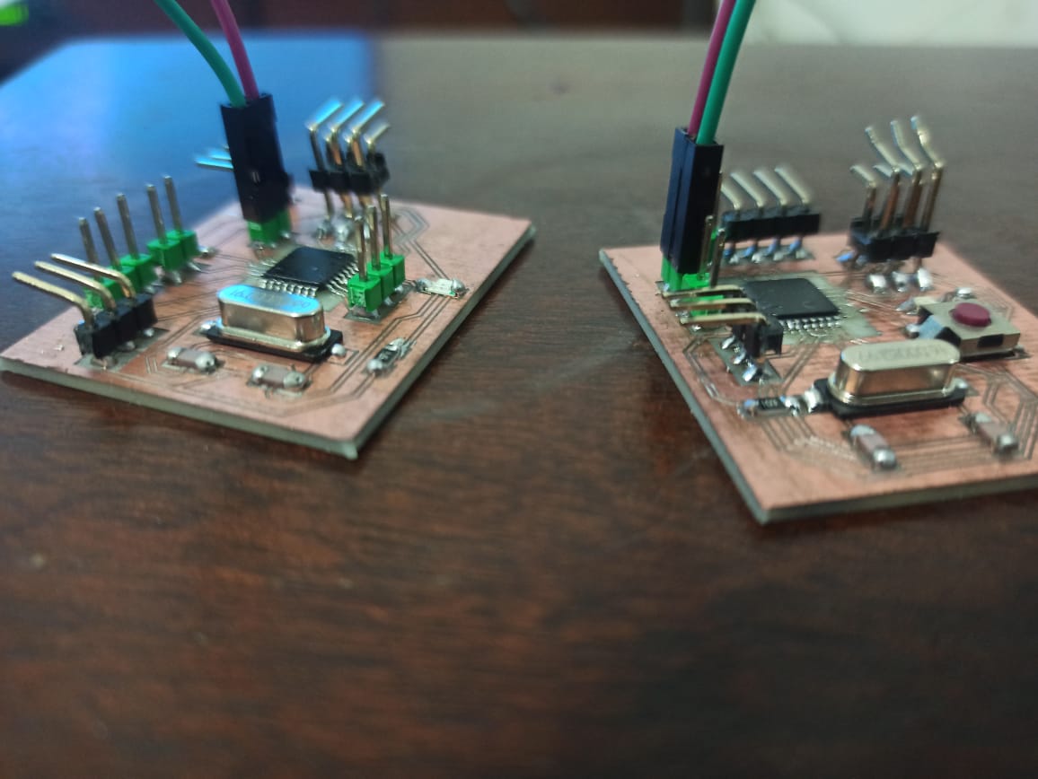
For the slave i m using the board from the input device and m going to design a board master as showing below
on the board master i attached a potentiometre (GND, VCC, A0)
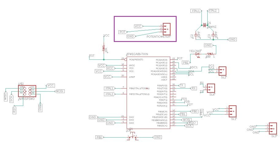
Potontiometre(GND, VCC, A0)
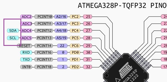
Based on the following connections i made the I2C protocol between the two boards
SDA (A4) to SDA
SCL(A5) to Scl
Now it is time to run the code
I started by including the Wire library (include
It s a built-in library for Arduino to make it able to work with I2C
It makes it very easy to communicate on the I2C bus, and it can configure the microcontroller to become either a master or a slave.
Then i had To define the slave adress (SLAVE_ADDR 9)
Since m using a potentiometer i need to define both the pin it is connected to and a variable to hold its value
int analogPin = 0;

int val = 0;
wire.begin() –> This initiates the library and sets up the microcontroller to be a master
In the Loop we read the potentiometer value and map it to a range of 01-255.
turning the potentiometer to the right increases the flash rate
delay(50);


val = map(analogRead(analogPin), 0, 1023, 255, 1);
beginTransmission() – This function is used by the master to send data to the slave.
Wire.write(val) it is to send the potontiometre value on the I2C bus
endTransmission() This function is used by the master to end a transmission
Now it’s just a matter of sending the byte to the slave and repeating the Loop again.
Here it is the master code
#include <Wire.h>

#define SLAVE_ADDR 9

int analogPin = 0;

int val = 0;

void setup() {

Wire.begin();

}

void loop() {
delay(20);

val = map(analogRead(analogPin), 0, 1023, 255, 0);


Wire.beginTransmission(SLAVE_ADDR);

Wire.write(val);

Wire.endTransmission();

}
To write the slave code
I started by the inclusion of the Wire library, as well as defining the slave address.
I also defined a pin for the LED
i defined a variable(rd) to receive data while the other carries the time delay value for the blink rate.
#include <Wire.h>

#define SLAVE_ADDR 9

int LED = 10;

int rd;

int br;
In the Setup define the pin for the LED as an output and initialize the I2C bus.
pinMode(LED, OUTPUT);
the slave address in the begin function make the Wire library knows that the slave is required
Wire.begin(SLAVE_ADDR);
I mnot requesting data from the master , so i need only to define an onReceive function.
Wire.onReceive(receiveEvent);
Finally, in the Loop i used the incoming data to blink the LED.i used the Map function to accomplish this
Here it is the slave code
#include <Wire.h>

#define SLAVE_ADDR 9

int LED = 10;

int rd;

int br;

void setup() {

pinMode(LED, OUTPUT);

Wire.begin(SLAVE_ADDR);

Wire.onReceive(receiveEvent);

Serial.begin(9600);

Serial.println("Hello i m I2C Slave ");
}


void receiveEvent() {

rd = Wire.read();

Serial.println(rd);

}
void loop() {

delay(50);

br = map(rd, 0, 255, 50, 2000);

digitalWrite(LED, HIGH);
delay(br);
digitalWrite(LED, LOW);
delay(br);

}
And yeah the code is working well :)
Now i’ll show you in this video how i control the led blinking using the pototiometre
Check all my files