Trap Making electronics
Smart trap
Electronic design
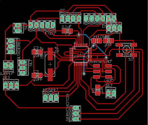
Board design
Here it is my first complexe board which is the controlling borad for the project. Im using :
-
atmega328p microcontroller
-
dht11
-
DS3231 as an input
-
LCD 2*16
-
Servo motor Mg996r as output .
-
For the enrgy i used a 12V battery.
-
AVRISPSMD For programming:
-
SMD CLOCK : 16 MHZ crystal
-
FTDI
-
Pinheaders for VCCs and GNDs
-
All my components need 5v thats why i used a voltage regulator 5v .
I was very careful about how i was designing the schematic to make sure that every thing gonna work perfectly
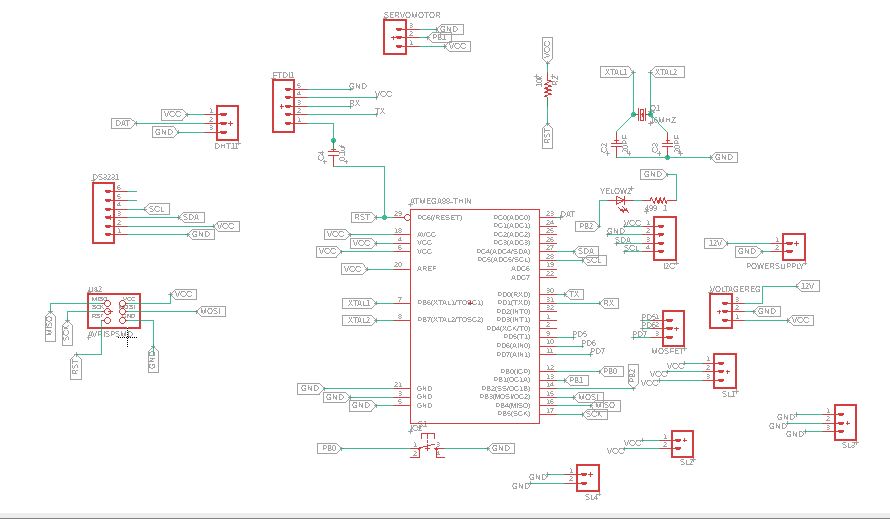
I tried to make extra pinheaders from analogue digital,VCC and GND pins in case i need it
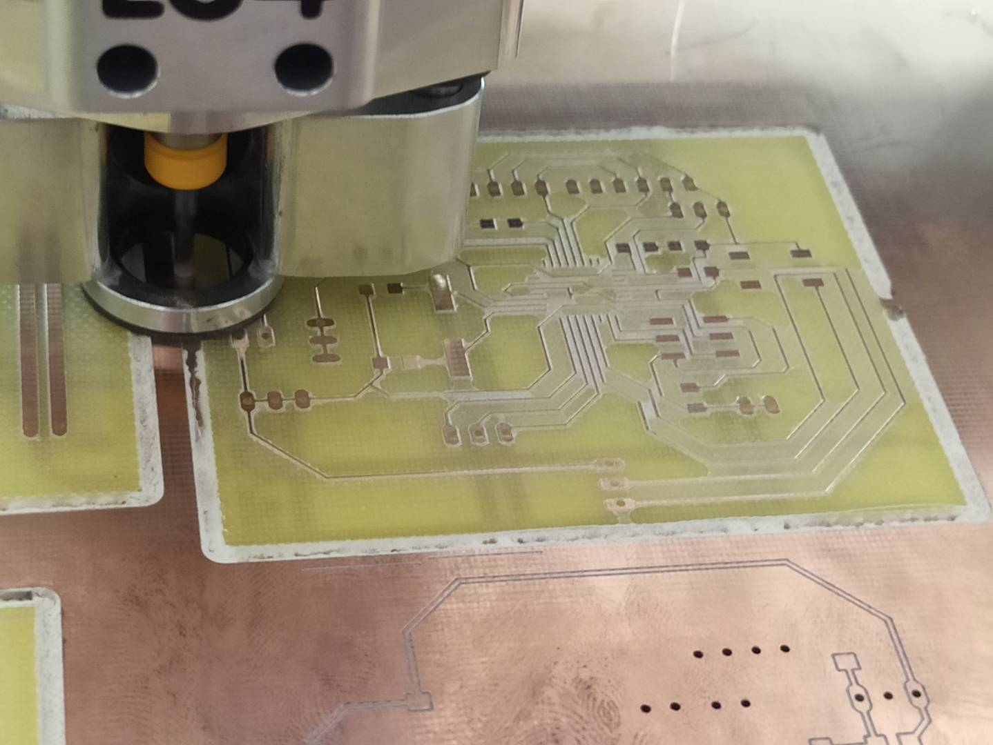
This was one from the hardest parts i ve been through , so itried to mill my board using the cnc of our fablab but it doesn’t work i changed the tool , i changed the parametres but it looks like it was a bigger problem so that’s why the fablab manager advice me to use another precise cnc if i want a good result , it is , For this I went to another fablab who have a high precision cnc for pcbs LPKF cnc
For this machine, we command & generate the g-code using the machine software. It works with GERBER file generated from Eagle
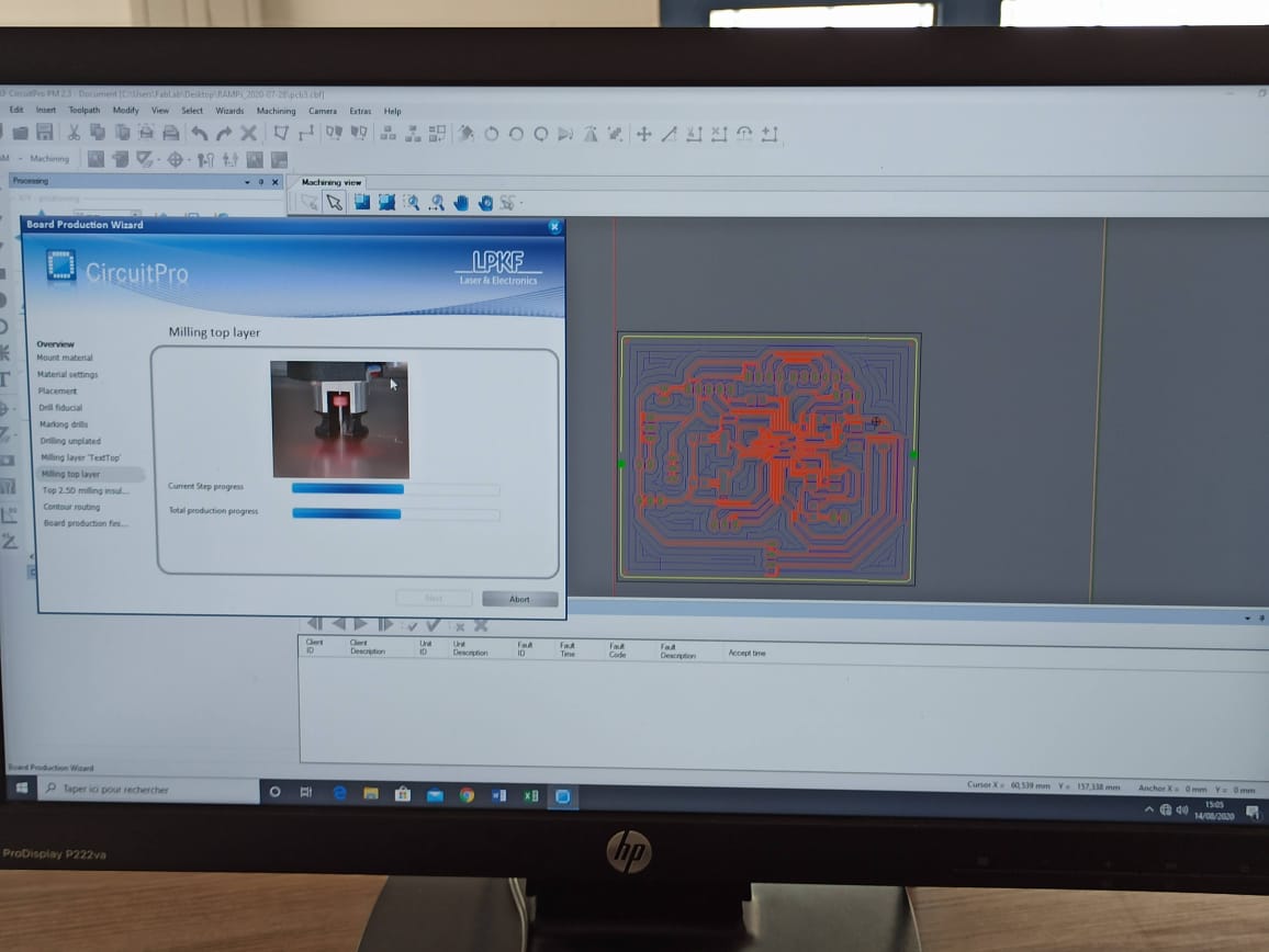
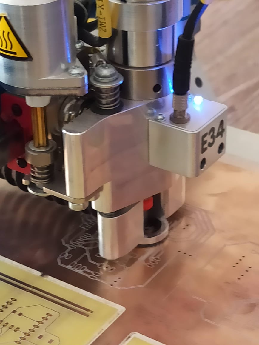
check this video
Soldering
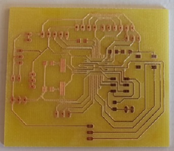
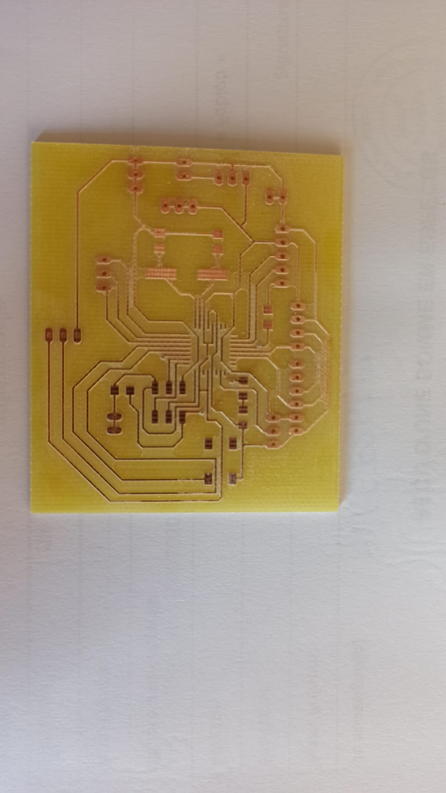
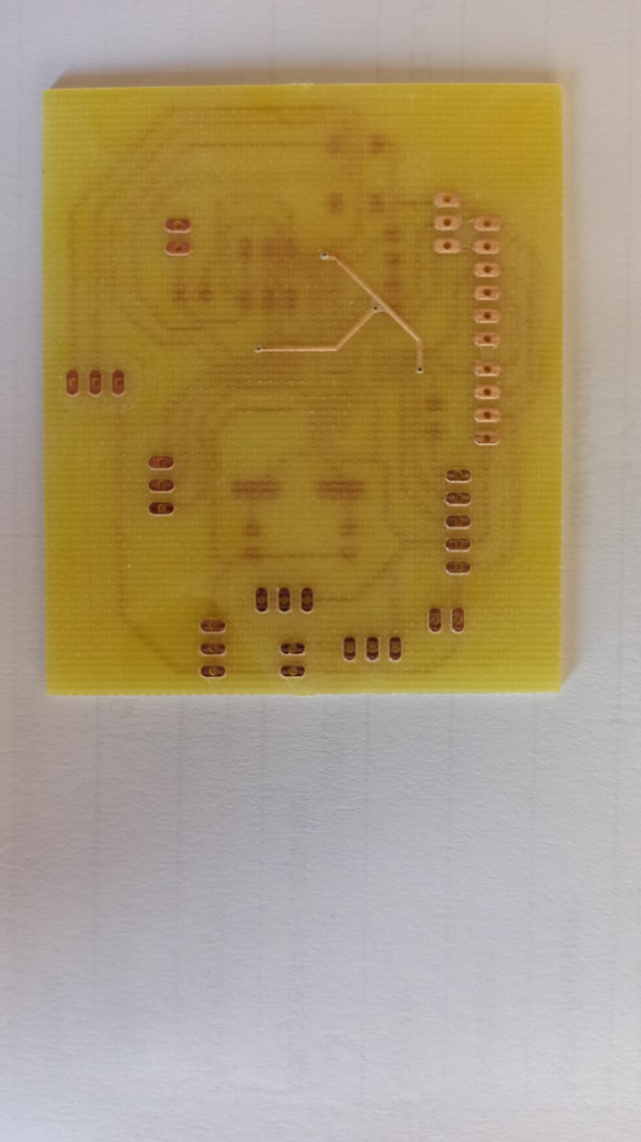
I m not really good at soldering so i was very careful to don’t damage the microcontroller and the components i passed more then 2 hours on it especially that it is a 2 layers board as showing bellow
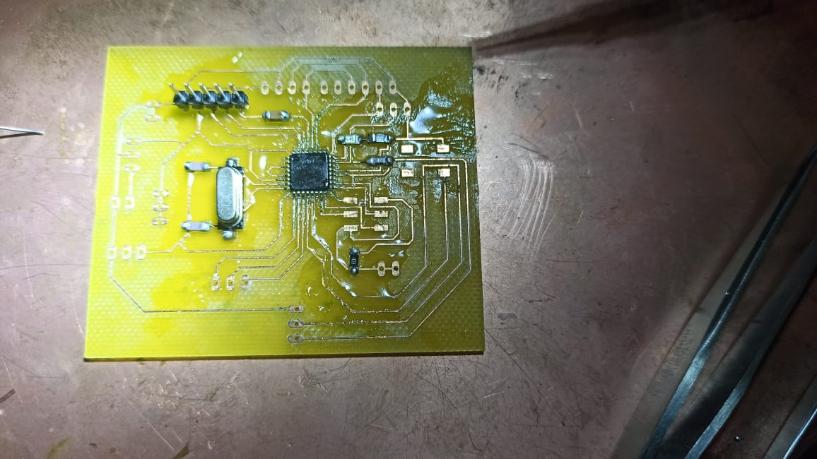
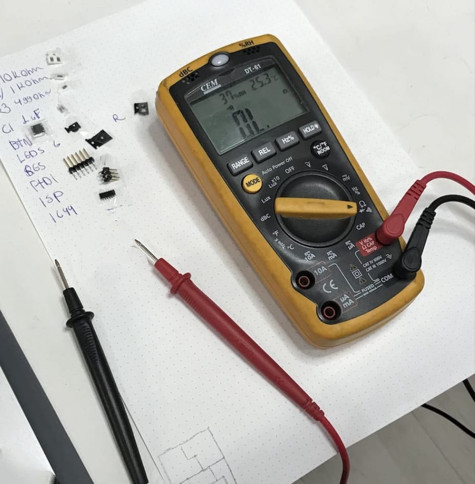
After soldering each component I was checking the connection every time using the multimeter to make sure that I didn’t make any fault especially when it was about soldering the battery VCC and GND connectors
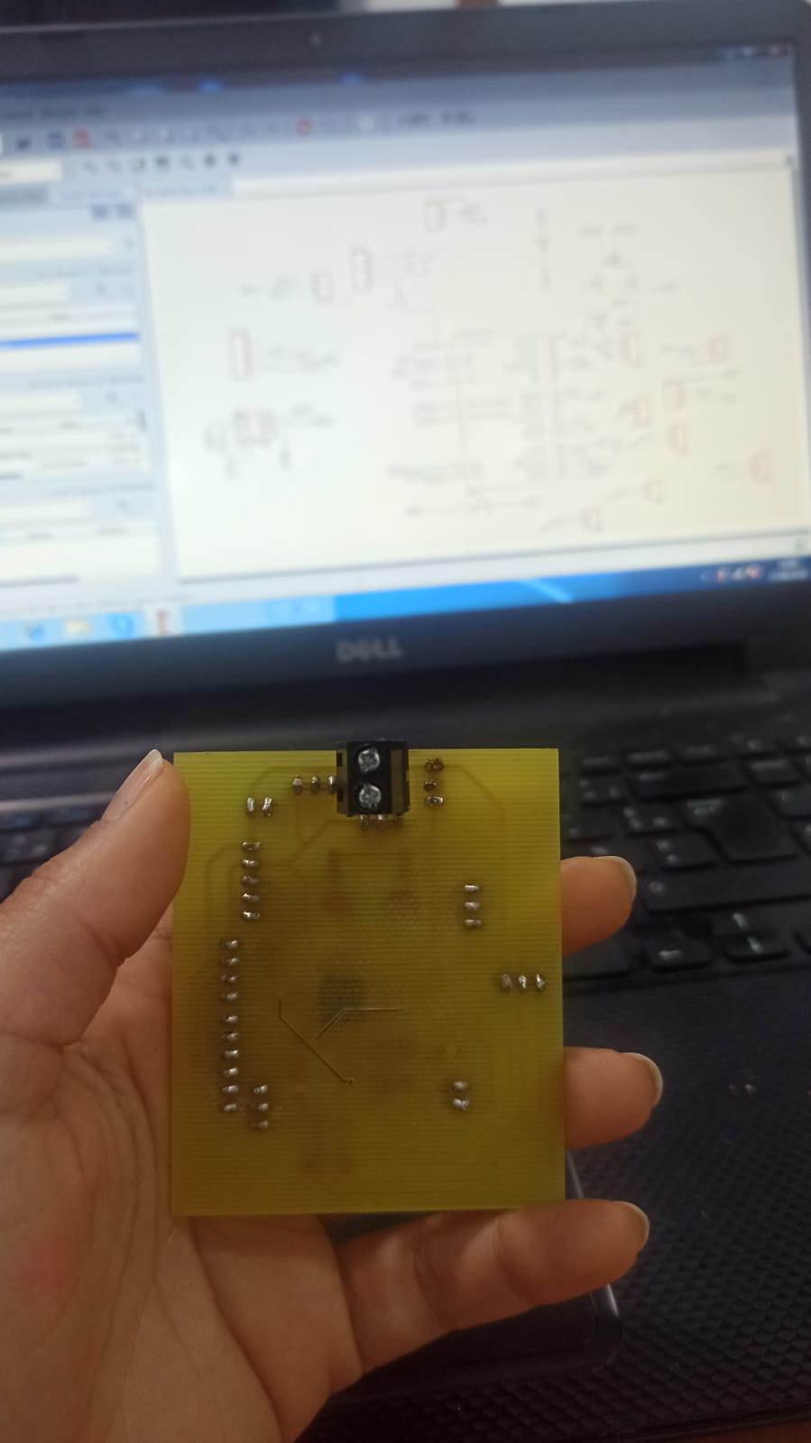
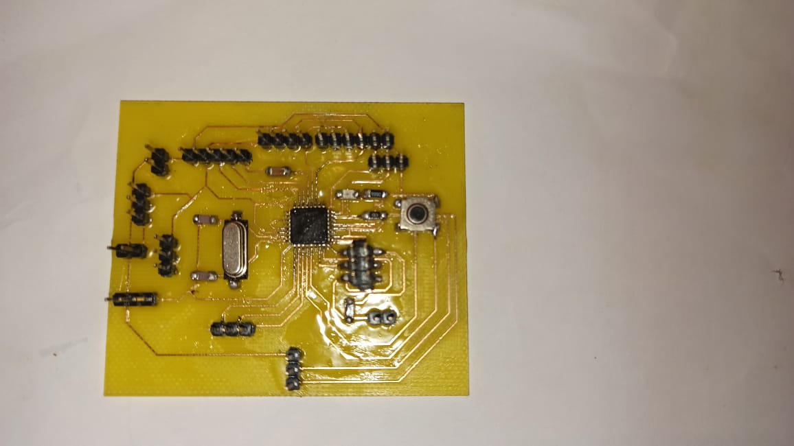
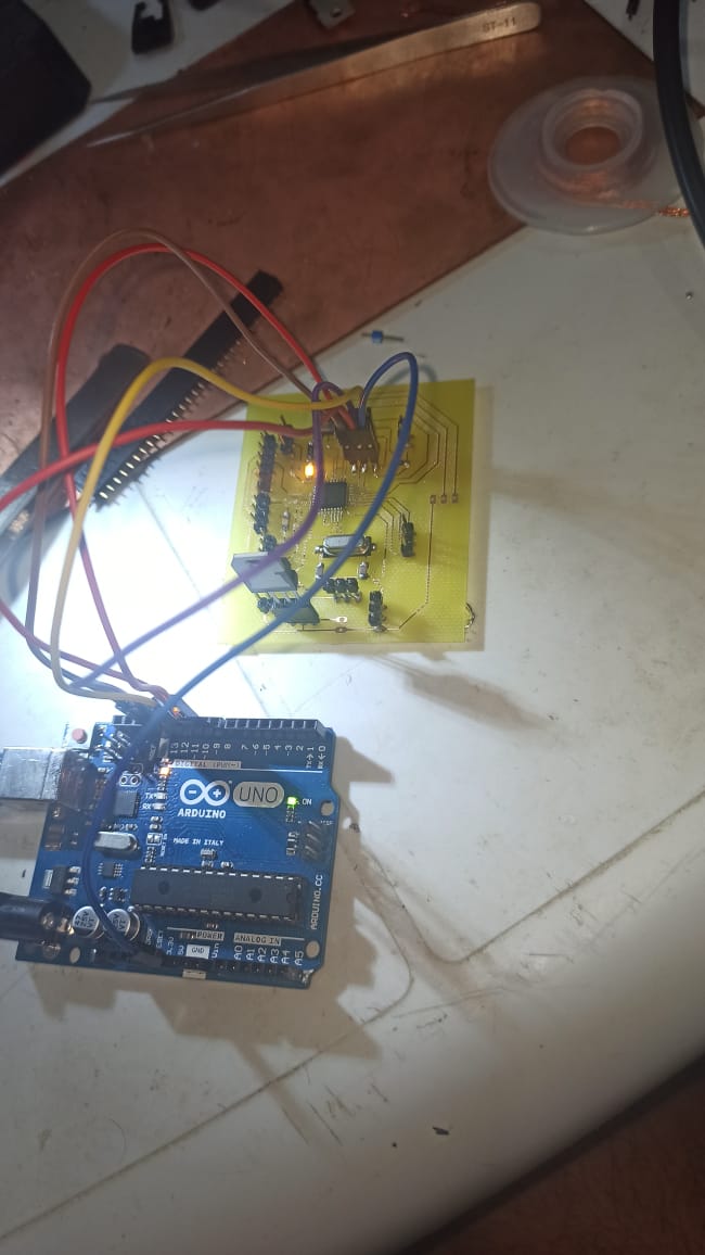
After soldering the board, Now it is time to see if i well do the soldering and the most important if my connections are okey , I used Arduino as ISP to program the board. I burned the boot loader successfully, and it looks like i m going in the right road
Check the final project schematic
Check the final project Board