12. Output devices
This week was the perfect week to learn about how to control different types of motor as I need it for my final project.
Group Assignment:
- Measure the power consumption of an output device.
Individual Assignment:
- Add an output device to a microcontroller board you have designed, and program it to do something.
Group assignment
Check this link to know what we have done to measure the power consumption of an
output device as a group assignment
Individual assignment
What an output device ?
An output device is any device used to send data from a computer to another device or user. Most computer data output that is meant for humans is in the form of audio or video. Thus, most output devices used by humans are in these categories. Examples include monitors, projectors, speakers, headphones and printers.
For the individual assignment I will add an LCD Display as an output to recieve data from DHT11(Humidity and temperature).
I need this data for my final project
2.LCD Display
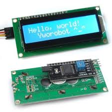
The display I chose to use for this assignment is a 16x2 character LCD Display
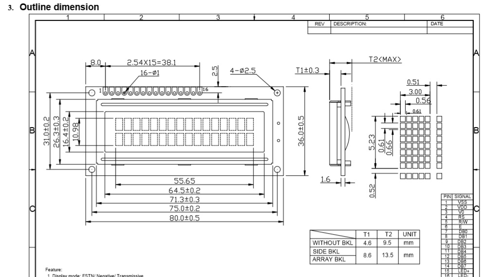
First i started by understanding its datasheet
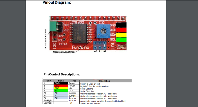
The I2C 1602 LCD module is a 2 line by 16 character display interfaced to an I2C daughter board. The I2C interface only requires 2 data connections, +5 VDC and GND
After learning how to use the i2c lcd i tried to program it
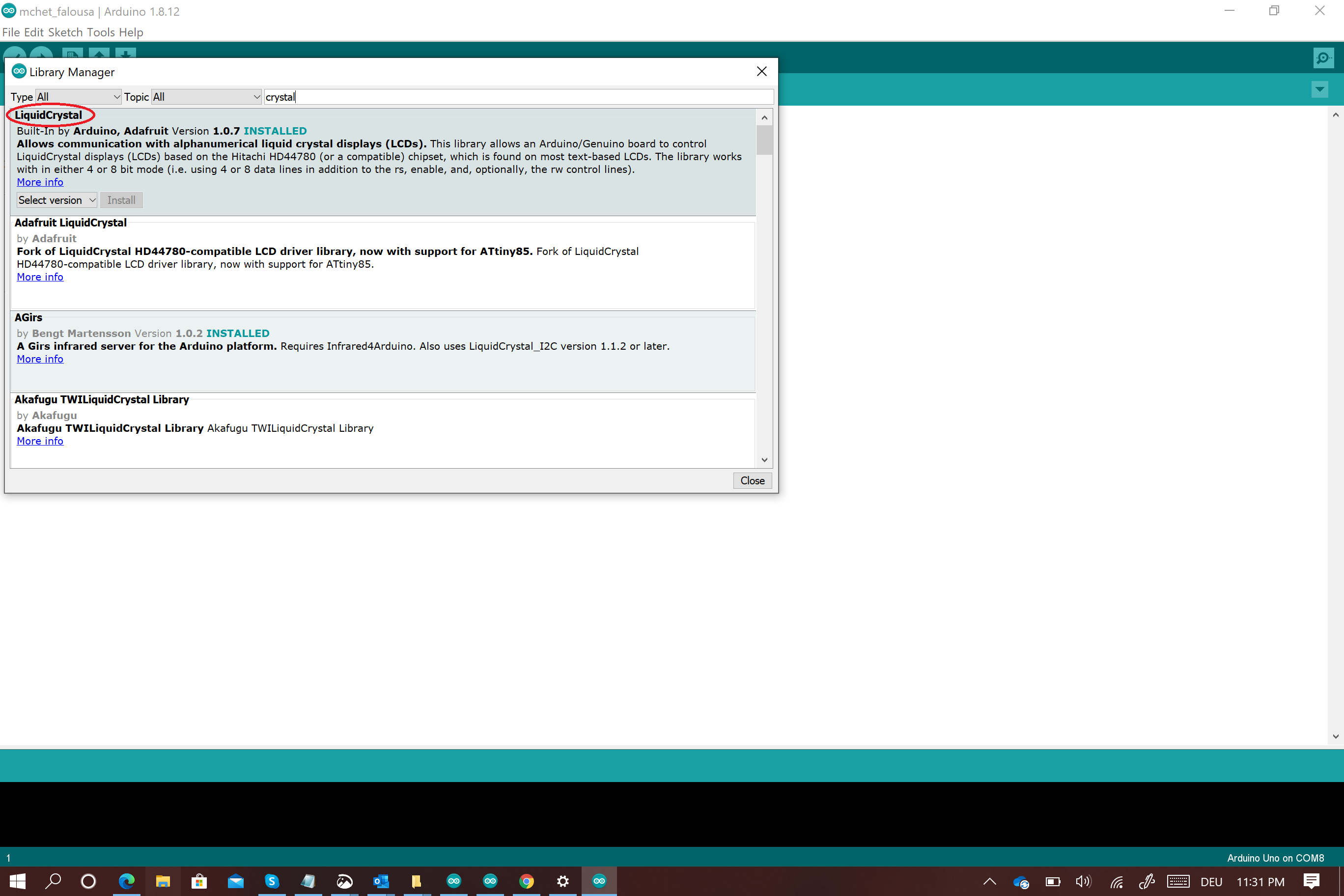
First i had to install a couple of libraries
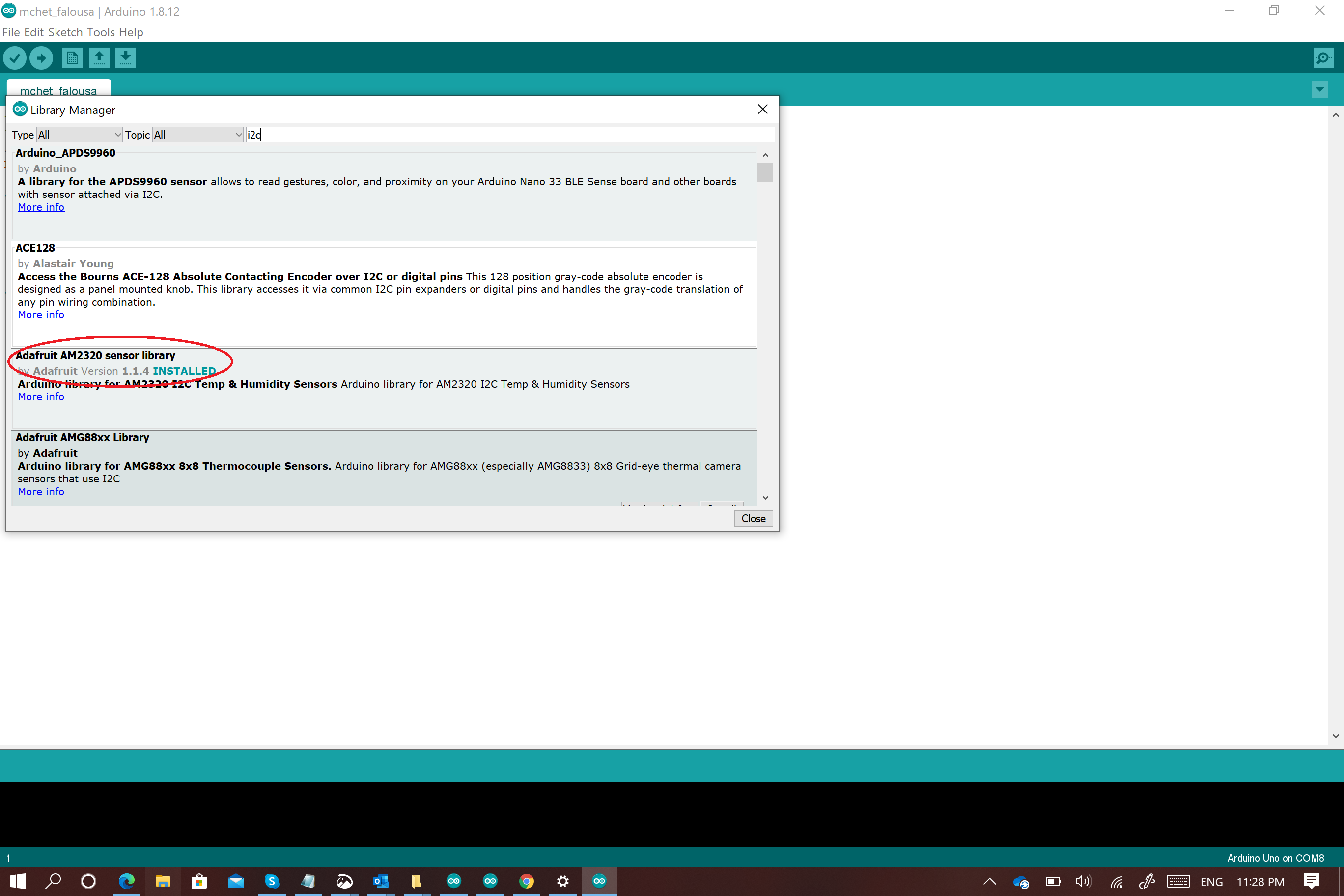
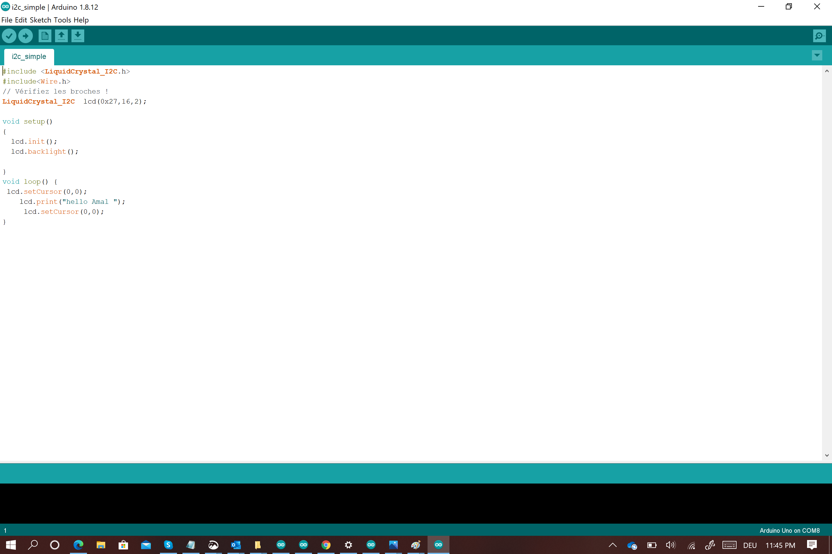
Then i used a very simple code just to make sure that thr LCD is showing Data and the contrast is well adjusted
The data which should appear on the LCD display is “Hello Amal”
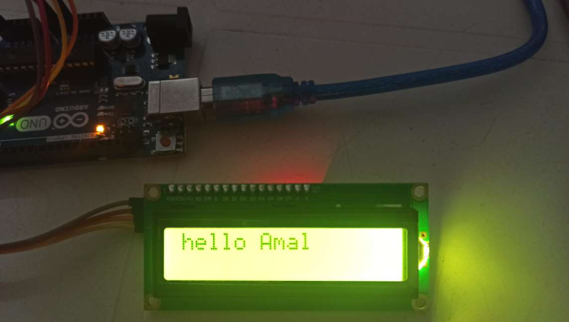
check this video
With this try i was sure that the LCD display works well and every thing was fine with the first code
Now it is time to run my code for the final project
I will create a code to read the DHT11 sensor and display the data in a LCD display through I2C communication.
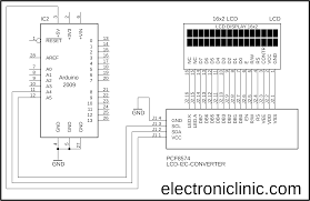
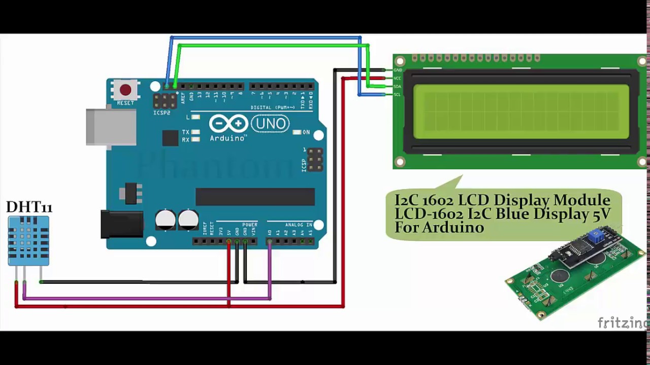
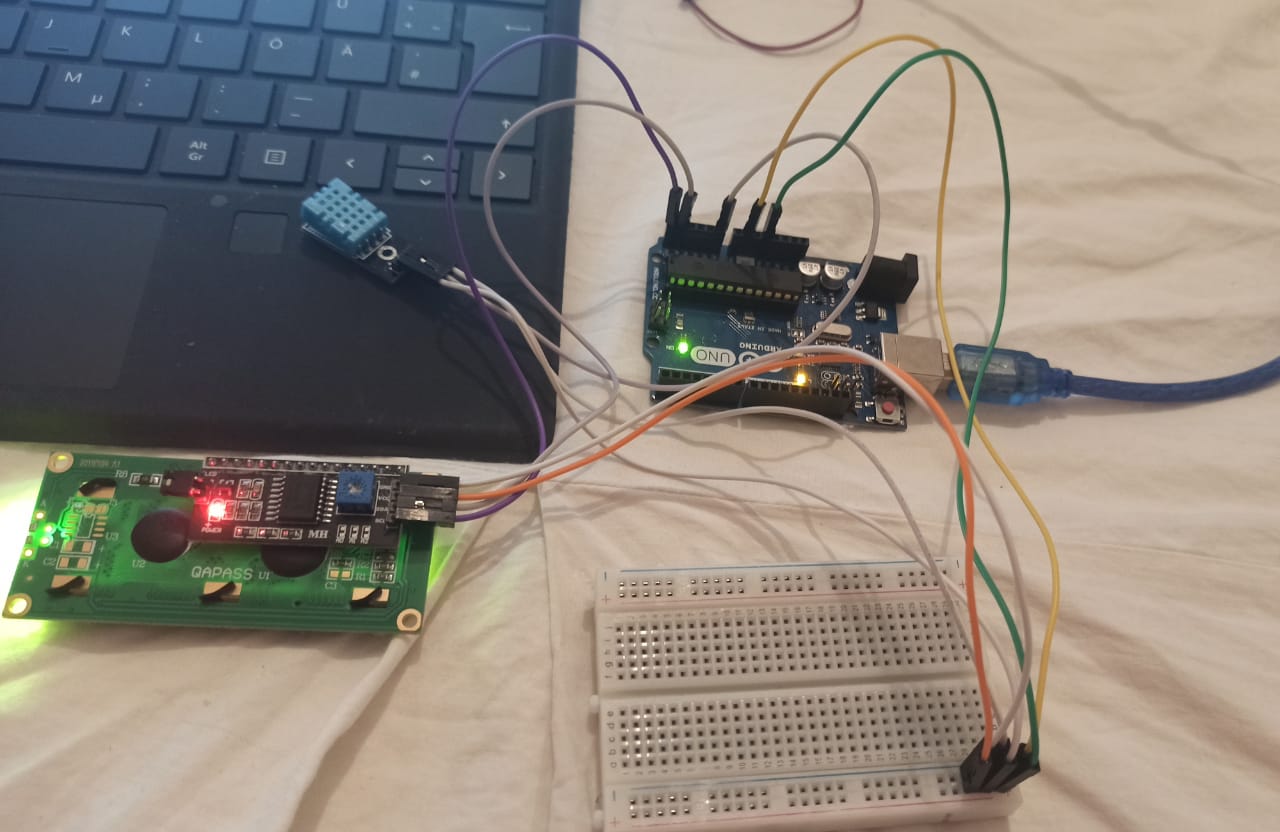
Before that I need to connect the i2c , the arduino and the DHT11 as following
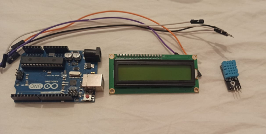
for that i need
An I2C 16*02 LCD module
Wires
Dht11 sensor
Arduino uno
Breadboard
for the DHT11
VCC to arduino vcc
GND to arduino Gnd
The data pin to A0 arduino pin
For the i2c lcd
SDA to A4
SCL to A5
VCC to vcc
GND to Gnd
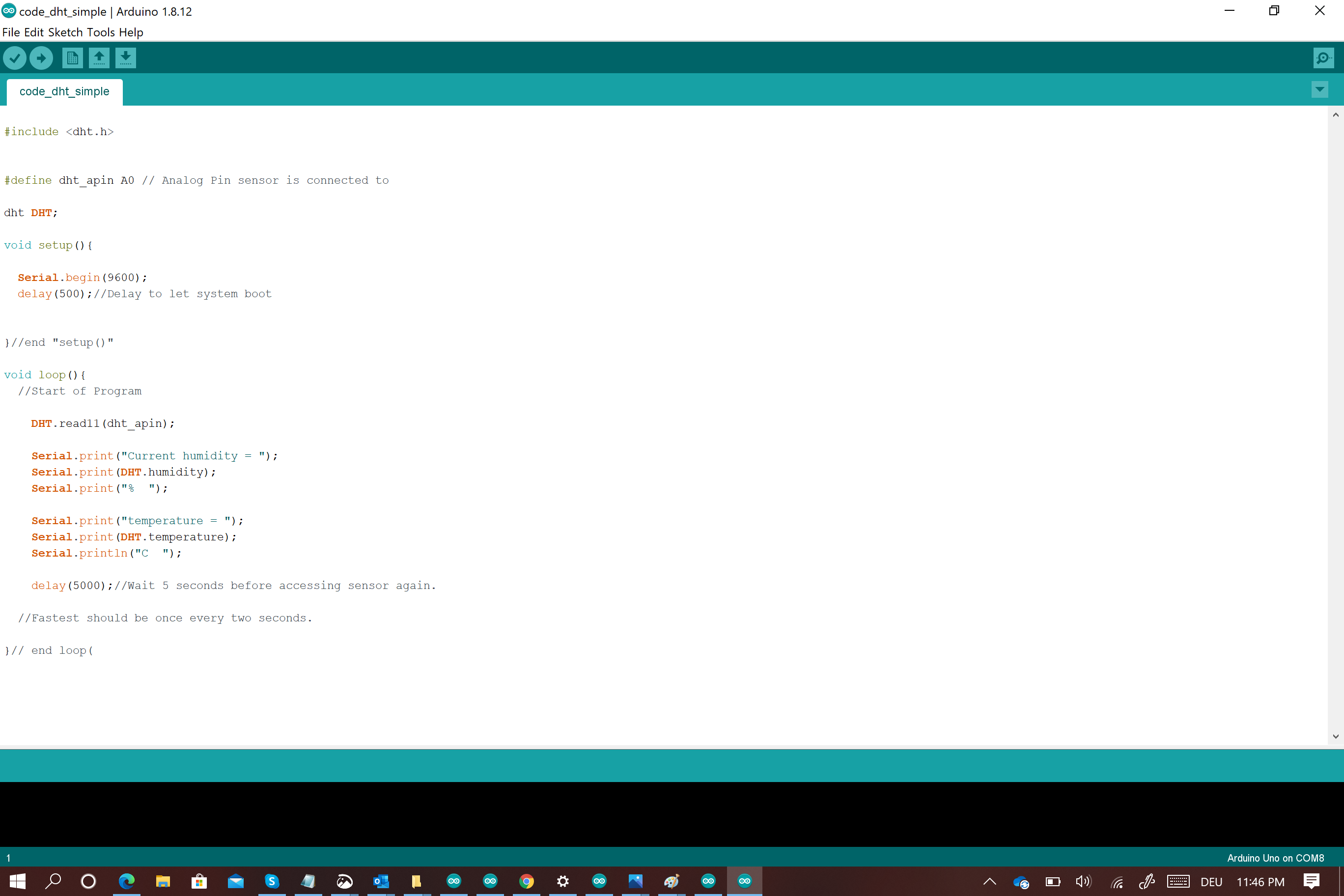
i created my code using a combination between the dht11 code which i used it for my input assignment and this lcd code
I started by including LiquidCrystal_I2C.h library
I defined my lcd adress(0x27) and size ((column,16), (row,2))
I also included the dht.h library and defined its pin where it is connected (A0)
To initialize the lcd i used this command (lcd.init())
To allow the LCD to send a message i used this command (lcd.backlight())
To read data from the DHT11 i used this command ( DHT.read11(dht_apin))
To set the LCD cursor i used this command (lcd.setCursor)
Now to read data(Temperature or Humidity ) from dht i need this command(DHT.read11(dht_apin))
To write the data on the LCD and to choose in which position (column, row ) i had to use these commands
lcd.setCursor(0,0);

lcd.print(" Humidity =");

lcd.print(DHT.humidity);

lcd.setCursor(0,12);

Serial.print(" humidity = ");

Serial.print(DHT.humidity);

Serial.print("%  ");
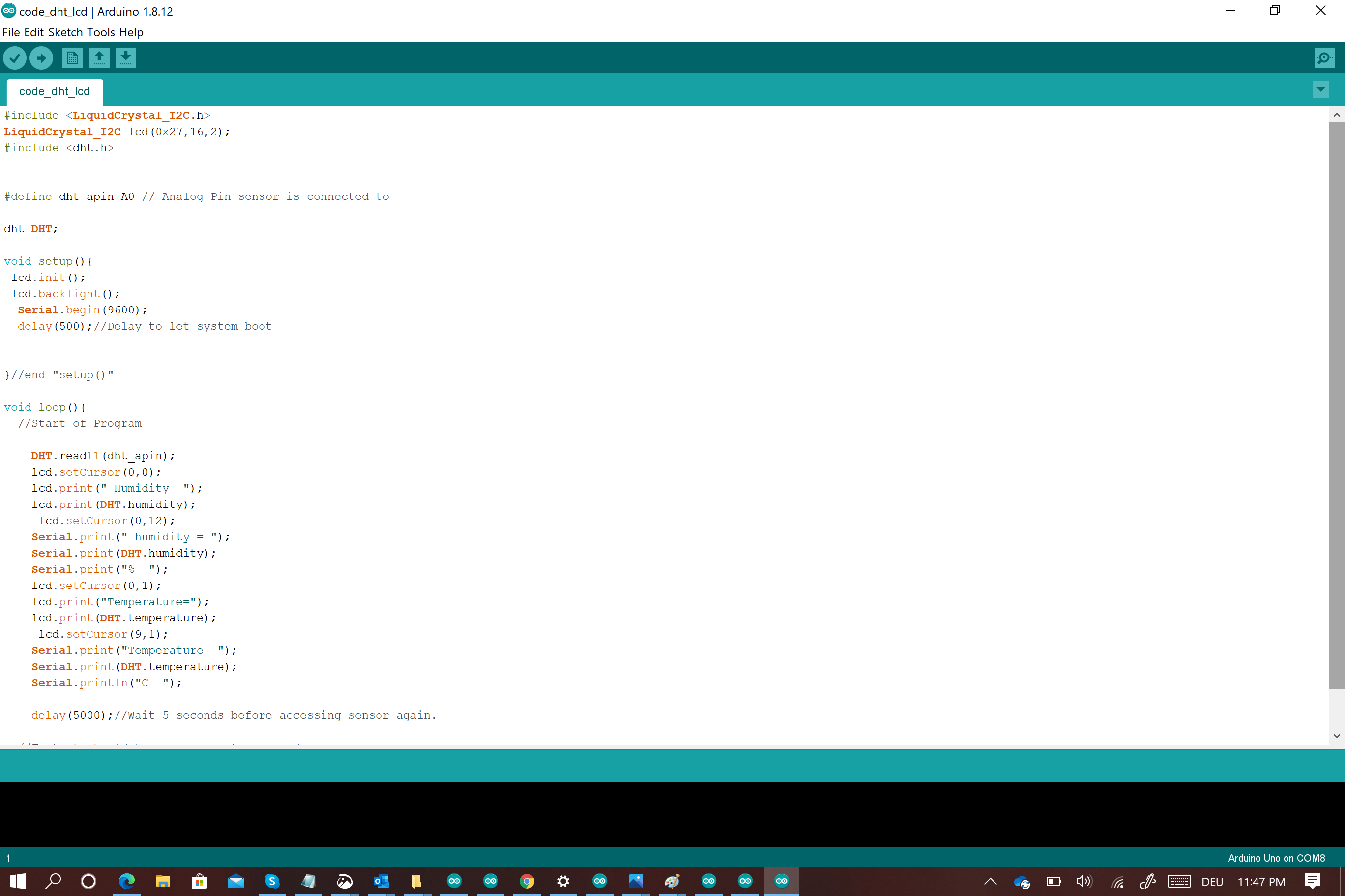
Here it is the final code :)
#include <LiquidCrystal_I2C.h>

LiquidCrystal_I2C lcd(0x27,16,2);

#include <dht.h>


#define dht_apin A0 // Analog Pin sensor is connected to

dht DHT;

void setup(){

lcd.init();

lcd.backlight();

Serial.begin(9600);

delay(5000);//Delay to let system boot


}//end "setup()"

void loop(){

//Start of Program

DHT.read11(dht_apin);

lcd.setCursor(0,0);

lcd.print(" Humidity =");

lcd.print(DHT.humidity);

lcd.setCursor(0,12);

Serial.print(" humidity = ");

Serial.print(DHT.humidity);

Serial.print("%  ");

lcd.setCursor(0,1);

lcd.print("Temperature=");

lcd.print(DHT.temperature);

lcd.setCursor(9,1);

Serial.print("Temperature= ");

Serial.print(DHT.temperature);

Serial.println("C  ");

delay(5000);//Wait 5 seconds before accessing sensor again.


}// end loop(
Every thing went alright and i can see my humidity and temperature data on the LCD screen
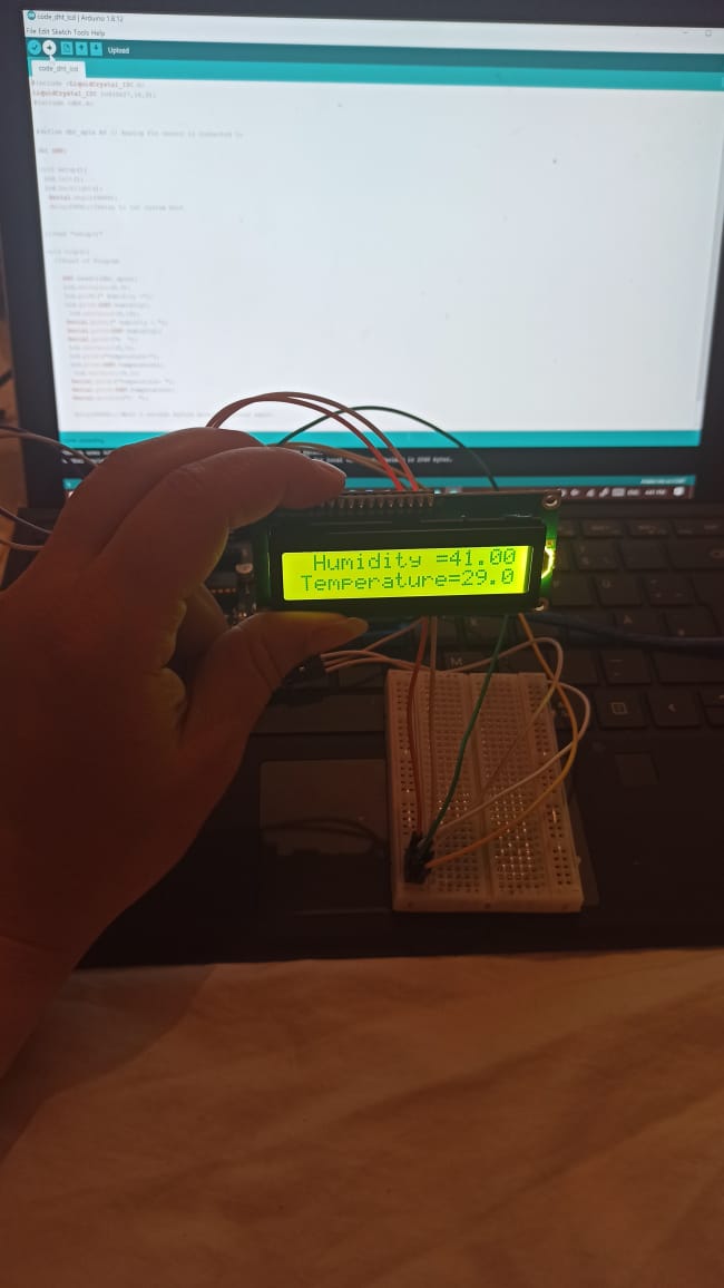
Check This video
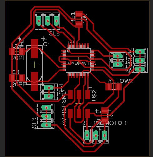
board design for the output
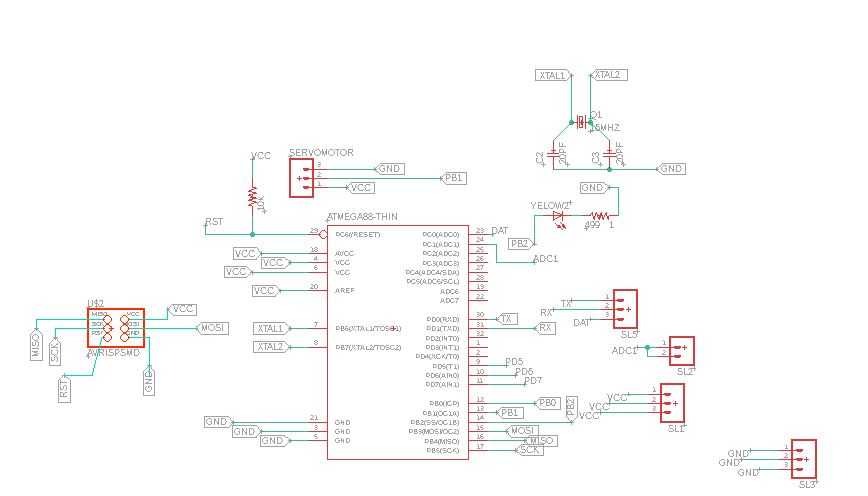
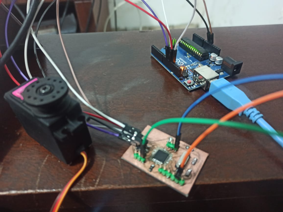
sine i m using a servo motor for my final project m going to design a board so i can rotate it I m using the atmega 328p since it i the only available microcontroller in my country as i explained in week 10 first i tried to read the servo motor mg996 datasheet

The connection is so easy
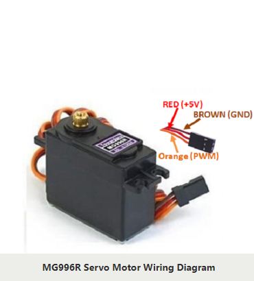
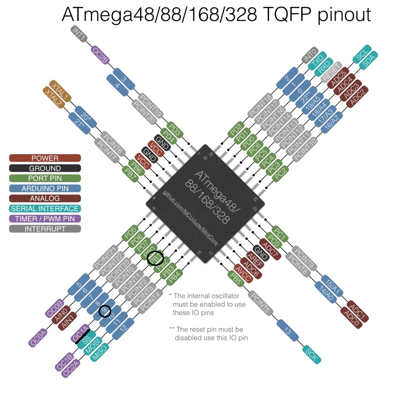
I had just to connect the servo to the Vcc , the Gnd and a PWM pin from the mirocontroller in my case i choose the pin PB1 which is a PWM pin as showing bellow
programming
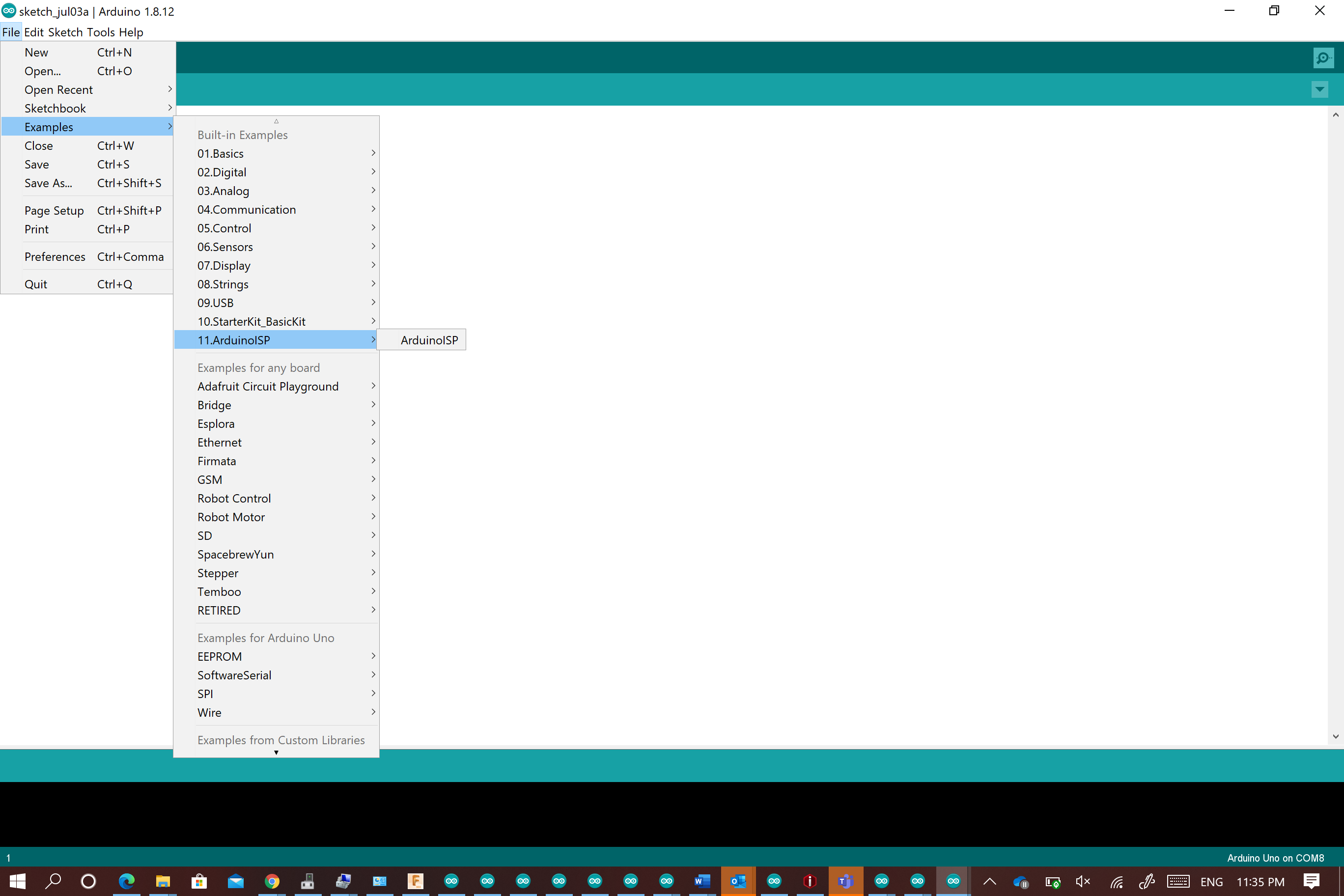
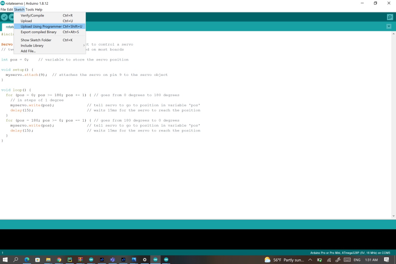
I used the arduino as programmer so first Connect the arduino to the computer
Go to the arduino software : file ->example ->Arduino ISP (This code will transfer the arduino into prgrammer)
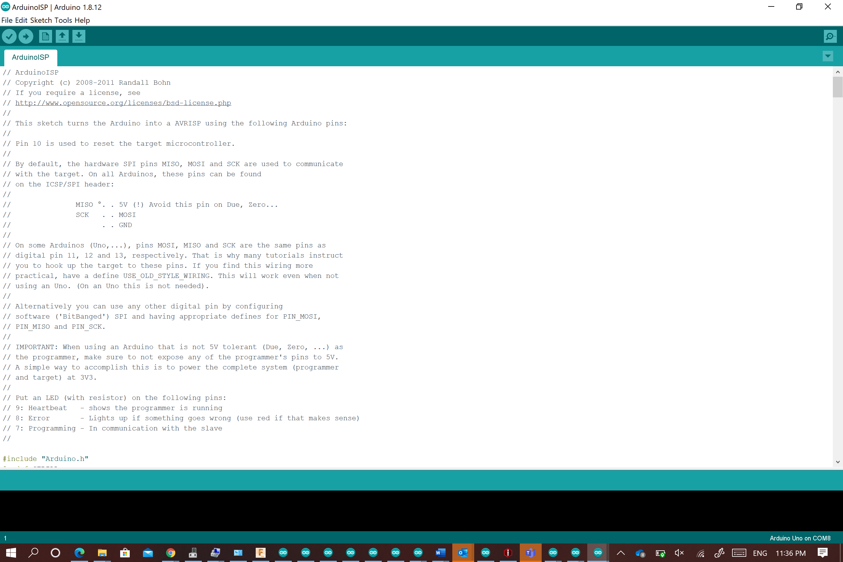
Now to download the servo code to the board :sketch -> upload using programmer and the servo will rotate
check the video
here you can find my files