5. Electronics production
This week is about electronic production. The basic intent of this week is to understand what a circuit is, the different types and components of a circuit board, milling a PCB and soldering. The area of electronics and its production was completely new to me. To begin with I started from the basics of Electronics. Terms of electtronics were quite alien to me. I started diving into the world of electronics step by step. The assignnment for this week was to make an ISP. Which includes various parts and processes.I don’t know how things will progress , let’s hope that every thing will be fine :)
Group Assignment:
- Characterize the specifications of your PCB production process.
Individual Assignment:
- Make an in-circuit programmer by milling the PCB, optionally trying other processes
What is a PCB?
PCB is an acronym for Printed Circuit Board. It is a board that has lines and pads that connect various points together. Before the advent of the PCB circuits were constructed through a laborious process of point-to-point wiring. This led to frequent failures at wire junctions and short circuits when wire insulation began to age and crack.
Solder is the metal that makes the electrical connections between the surface of the PCB and the electronic components. Being metal, solder also serves as a strong mechanical adhesive
Group assignment
In the the group assignment we are required to know our machine capabilities by milling some test samples already given on fabacademy website.
You can check this link
Individual assignment
As it was required For this week’s assignment, i need to make an in-circuit programmer. mill the board, stuff it with components and program it.
What is the FabISP?
The FabISP is an in-system programmer for AVR microcontrollers, designed for production within a FabLab. It allows you to program the microcontrollers on other boards you make.
To do this, there are 6 main steps:
-
Preparing files.
-
Preparing your machine.
-
Mill your board.
-
Cut your board.
-
Solder components.
-
Programming the board.
Now. let’s begin with milling the board!
Preparing files:
So, for the traces, we already had FabISP traces and outline cutout ready to download from here
Files were downloaded in png form

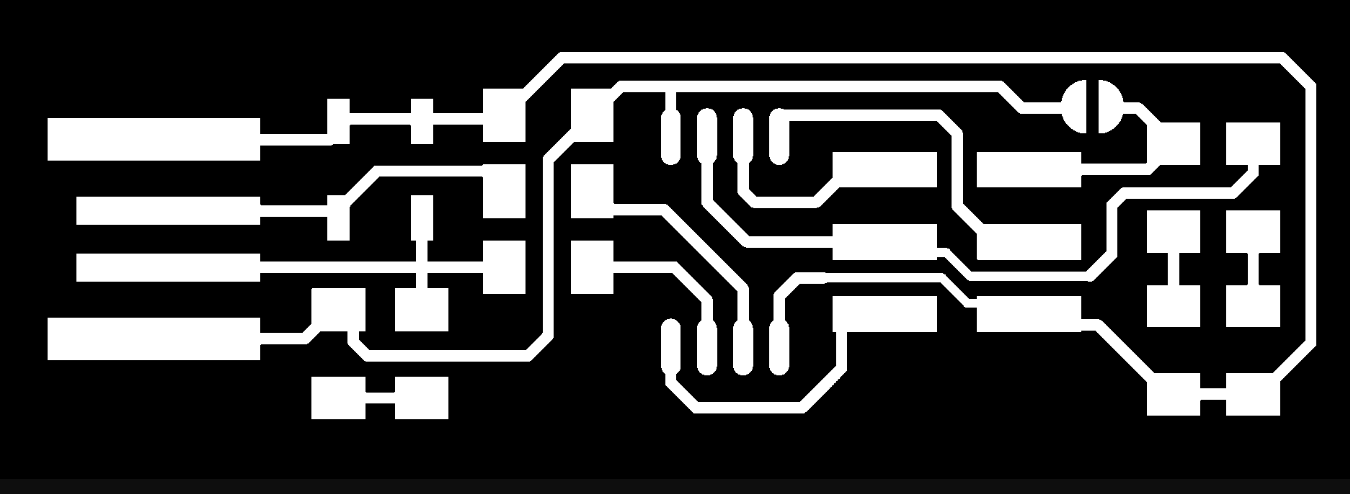
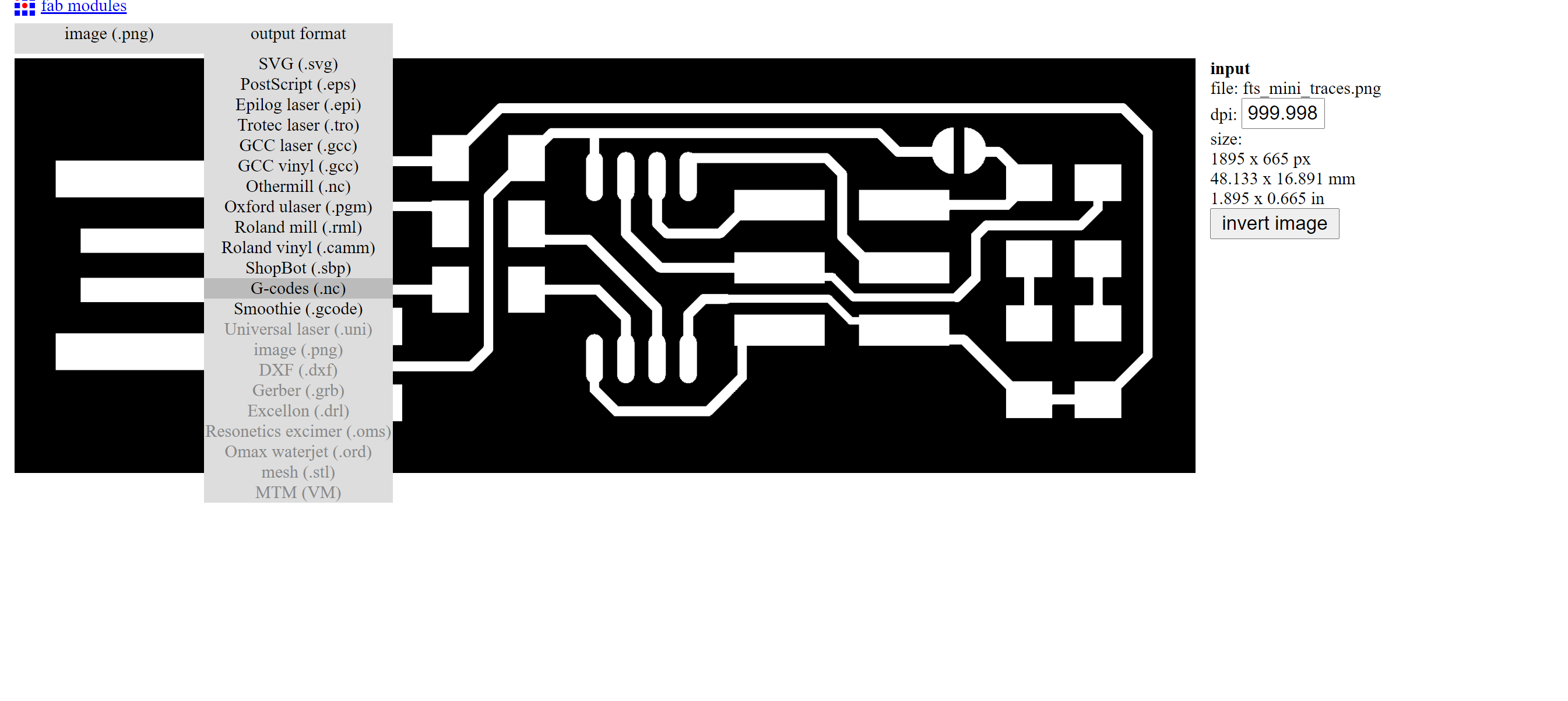
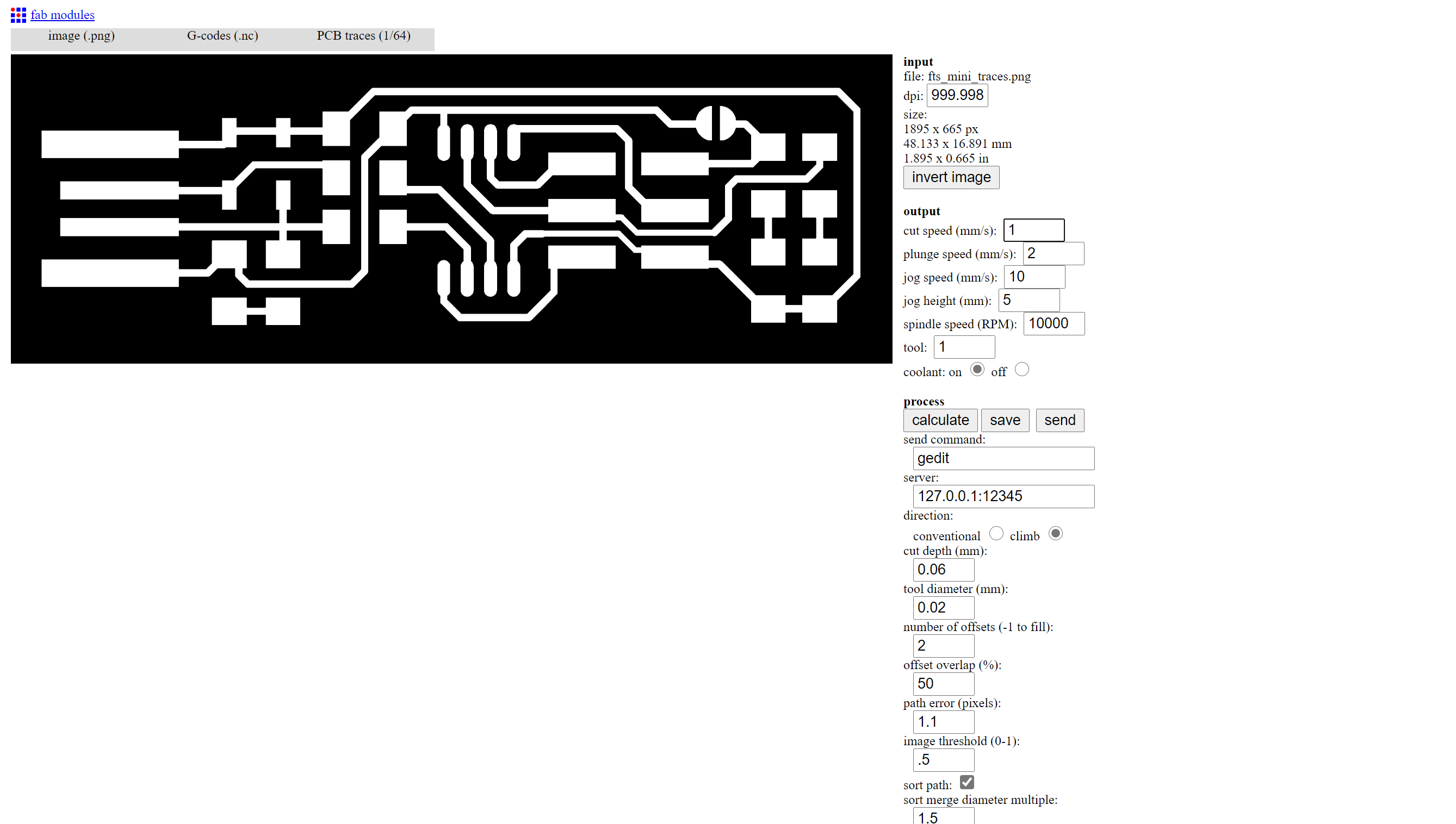
I used Fabmodules online at FabModules to upload the .png images successively and to generate the G-code for the CNC mill to mill the traces and to mill the outline shape of the PCB.
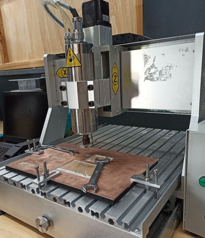
Preparing the machine
Use double sided tape to fix your piece of copper on the machine bed.
-
Mount your mill bit carefully in the collet.
-
Start moving your machine to the start point you want using “X min, Ymin” and “Move to Xmin and Ymin” features.
-
Zero your Z axis, and this is by moving your machine to the bottom carefully using the down button.
for accomplishing the following operation without risk of damaging the drill tip,you have to lower manually (slowly and by heavily controlled steps!)
When you are close to the copper sheet (around 0.5 mm), loosen the mill bit and allow it to slip slowly till it touches the surface of the copper. 5. Now the last step is to choose the G code that you have already prepared and send it !
I n my case i have already ^prepared my two G codes for the traces and the cut out as showing bellow
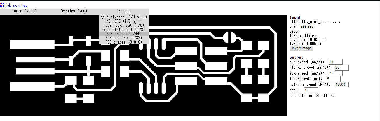
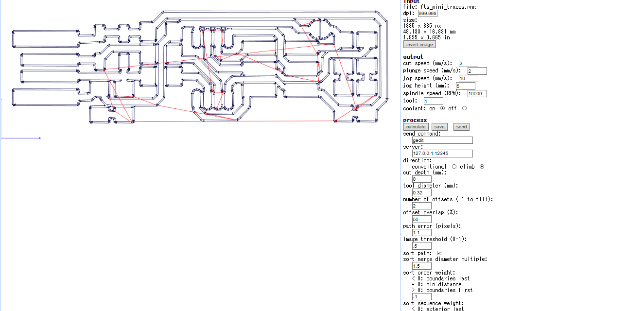
first i had to open fabmodules , then open the png file and fix the parameters, calculating the tool path and downloading the G-codes file for the CNC to start working .
I had to repeat the same process with the cutout png file
Solder components
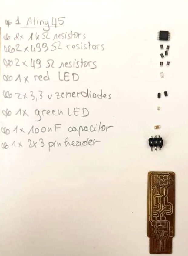
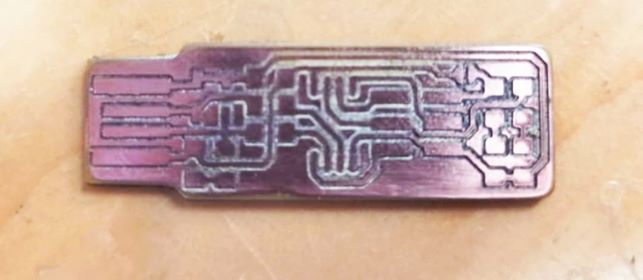
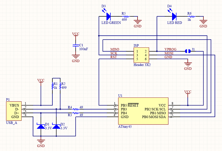
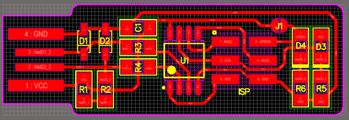
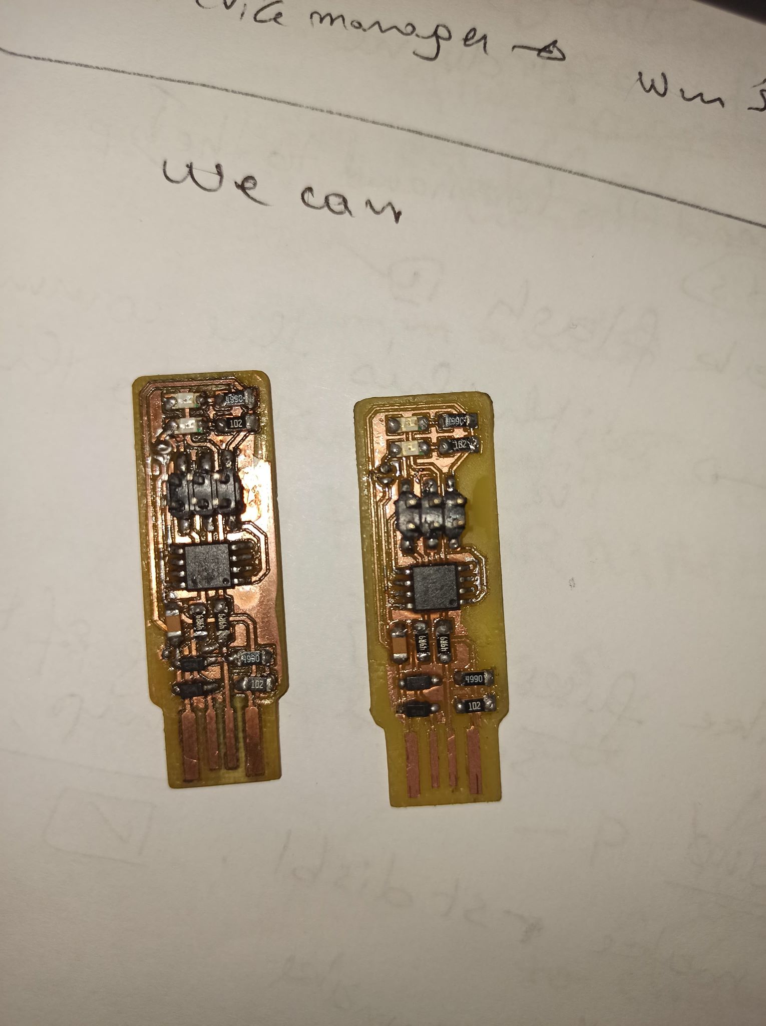
I soldered the parts to the PCB, using the schematic and board image below as a reference for component values and placement.
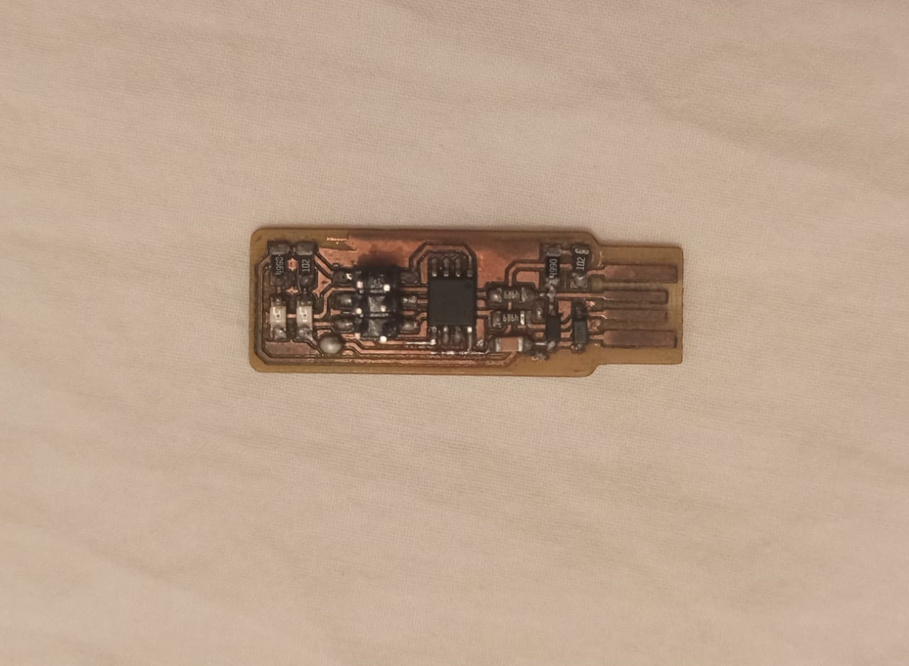
Here it is the final result , i think i did it well :)
Programming Board
The first step is to download
Connect the arduino to the computer
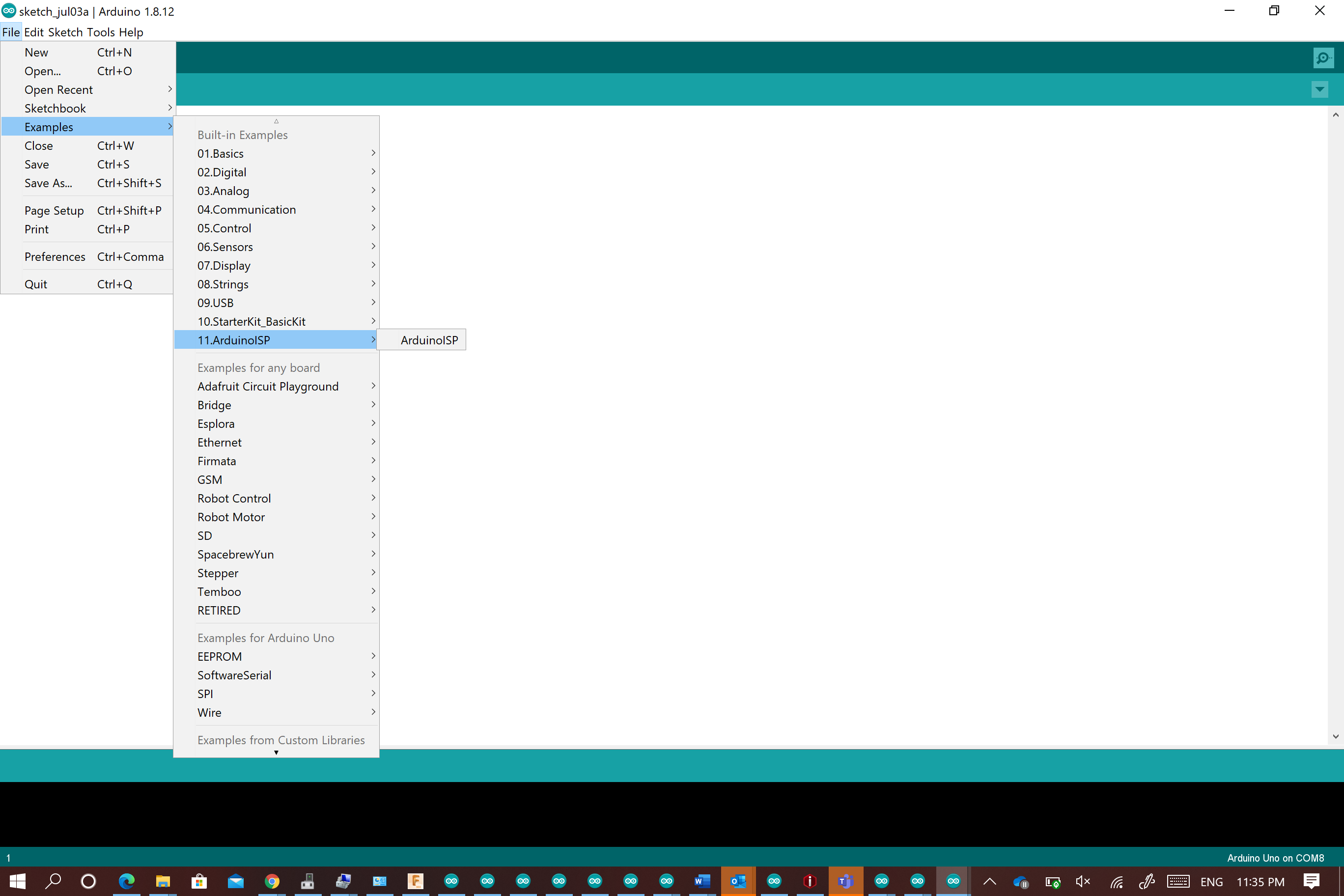
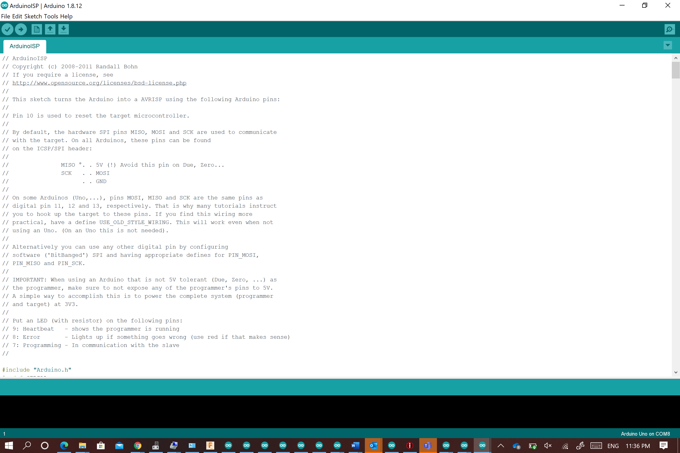
Go to the arduino software : file ->example ->Arduino ISP (This code will transfer the arduino into prgrammer)
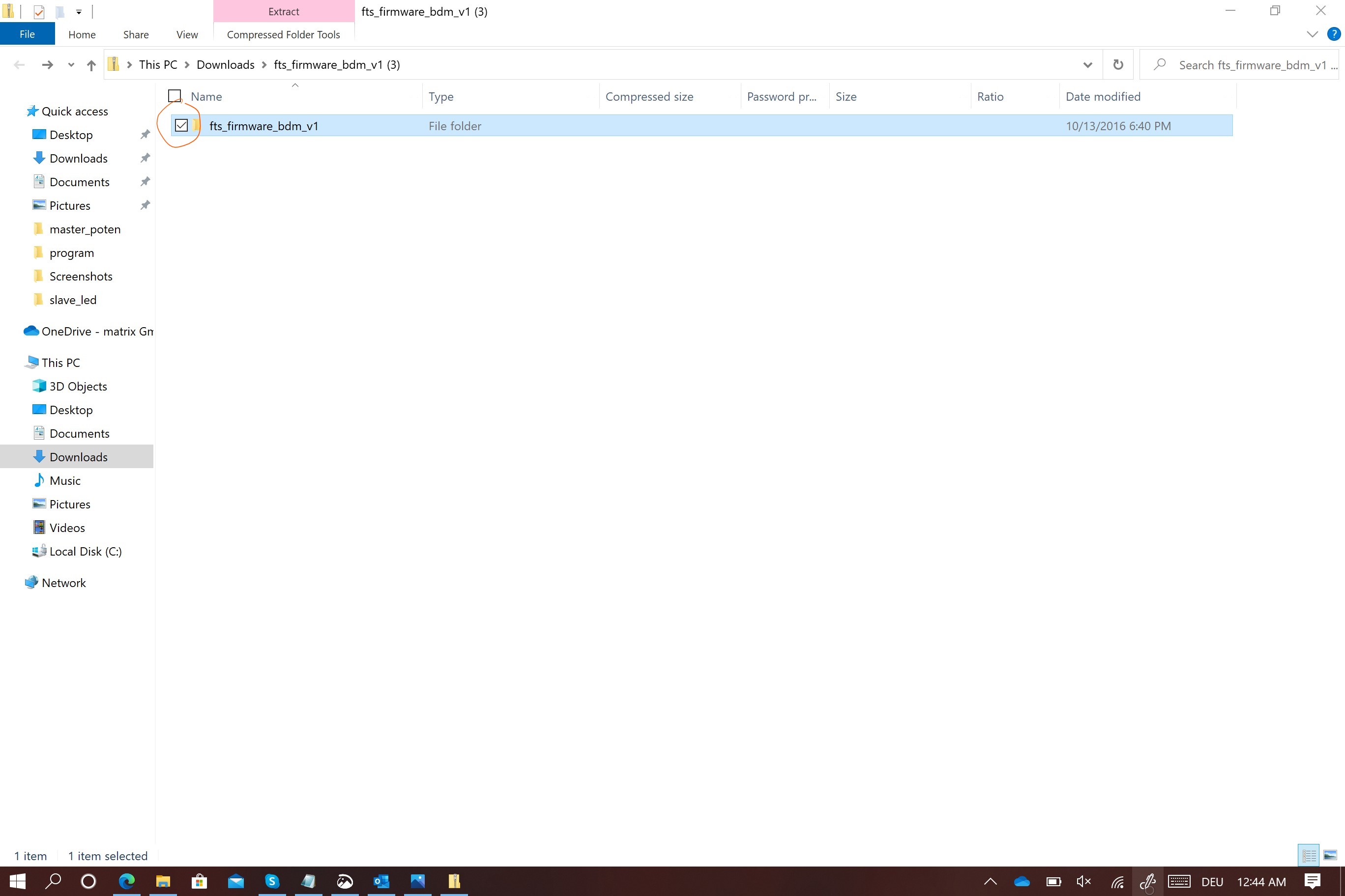
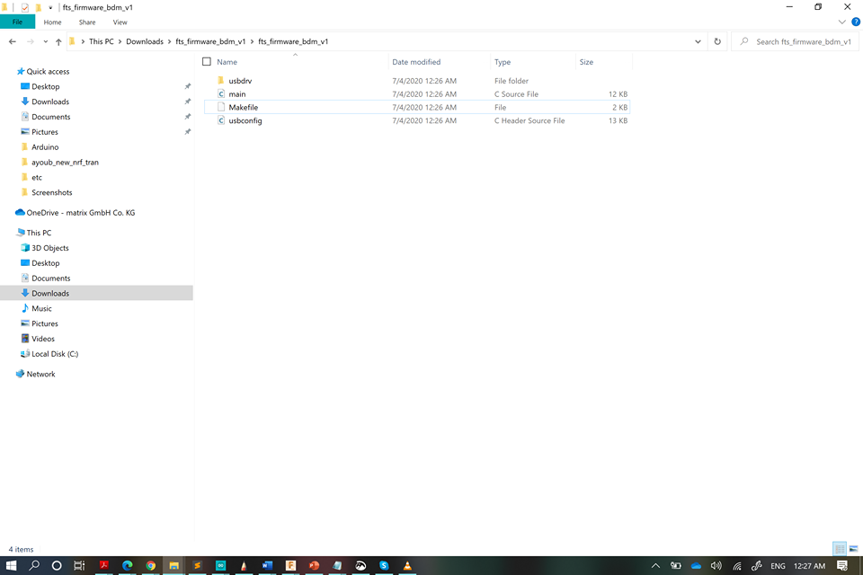
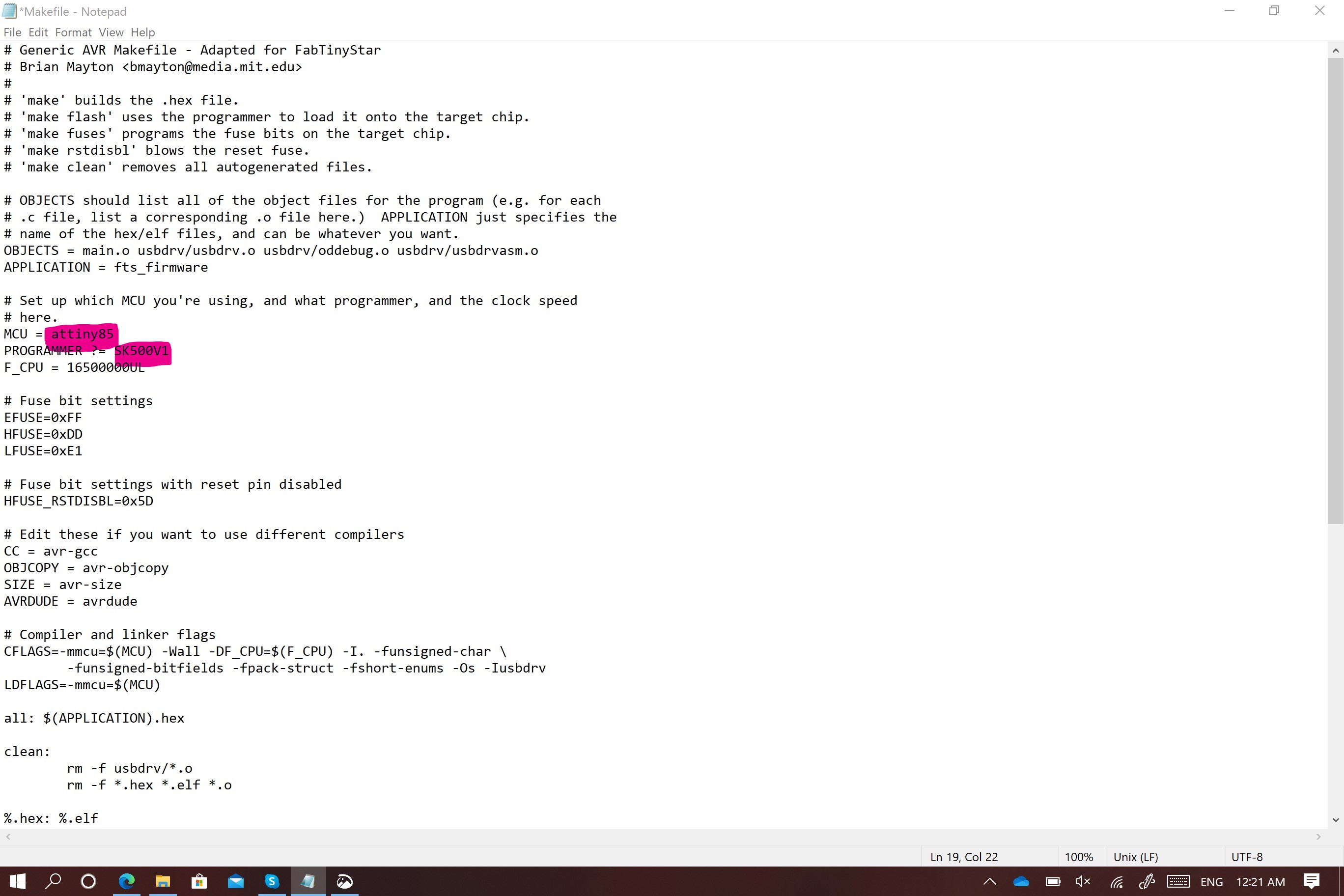
Disconnect the arduino and go to the notepad file , this file is made for the ISP that ‘s why we need to make some changes so it becomes able to work with arduino .Before that you need to extract the Zip files that you downloaded previously
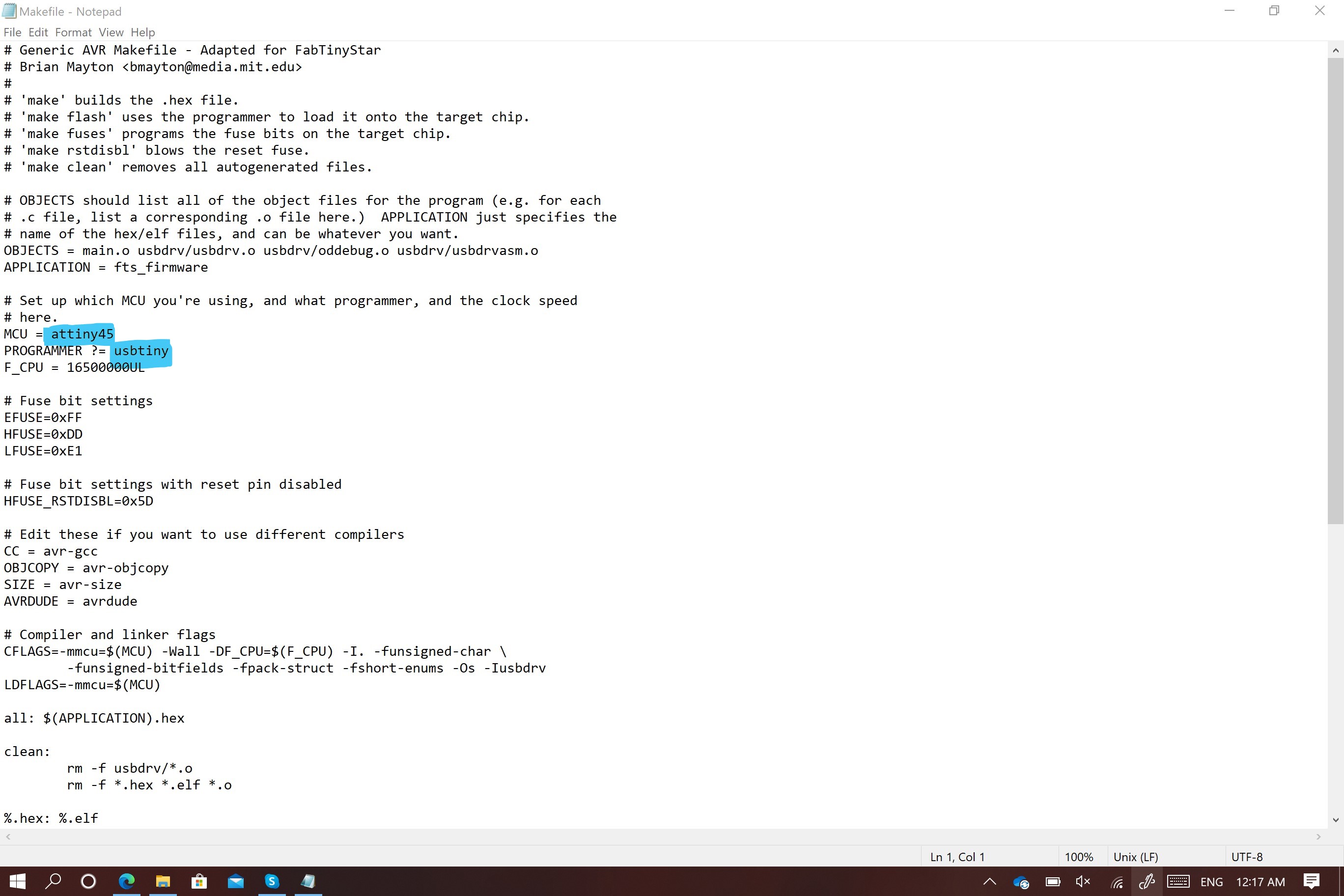
The first change is to modify the MCU=ATtiny85
The second change is the programmer=SK500V1
The third change is the port com6 and the spped 19200
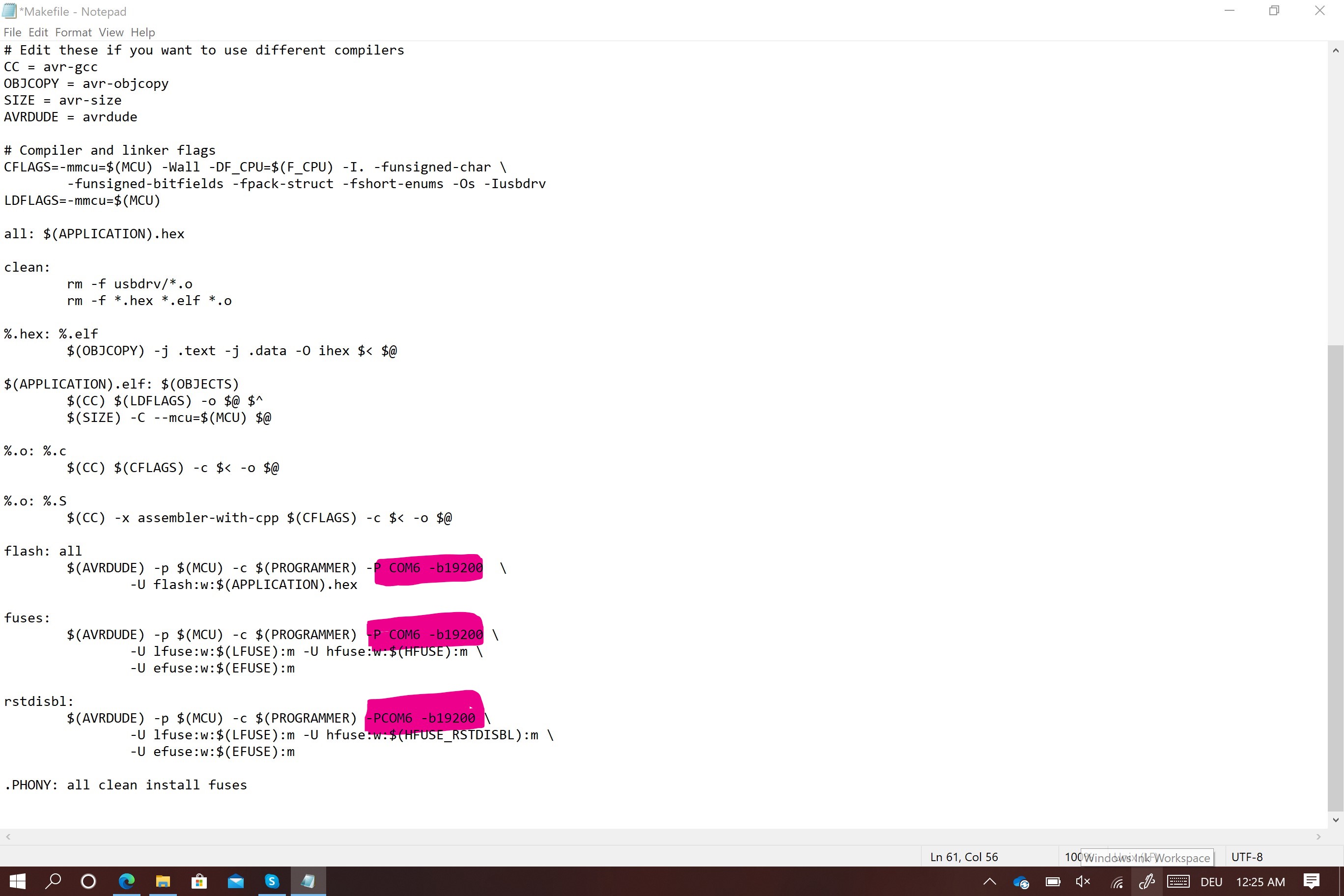
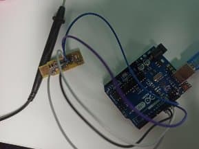
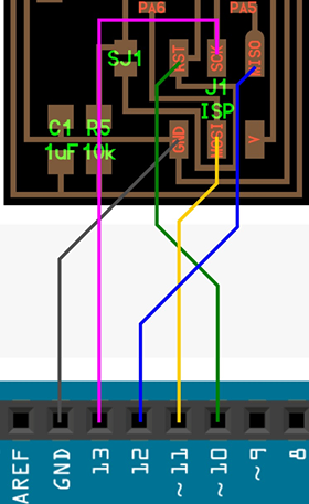
save changes .Connet the arduino with fab isp using jamper cables following the connections bellow and reconnect the arduino to the laptop
Now, you need to reopen the same folder as before and right click on the mouse and select git bash here .
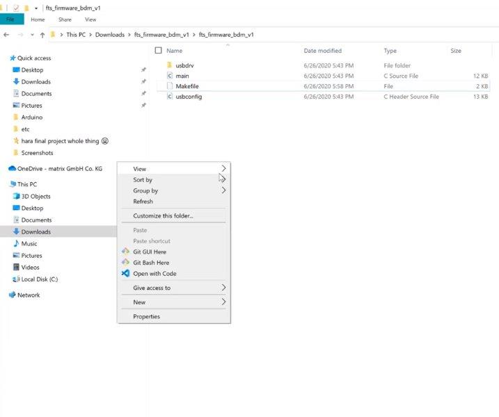
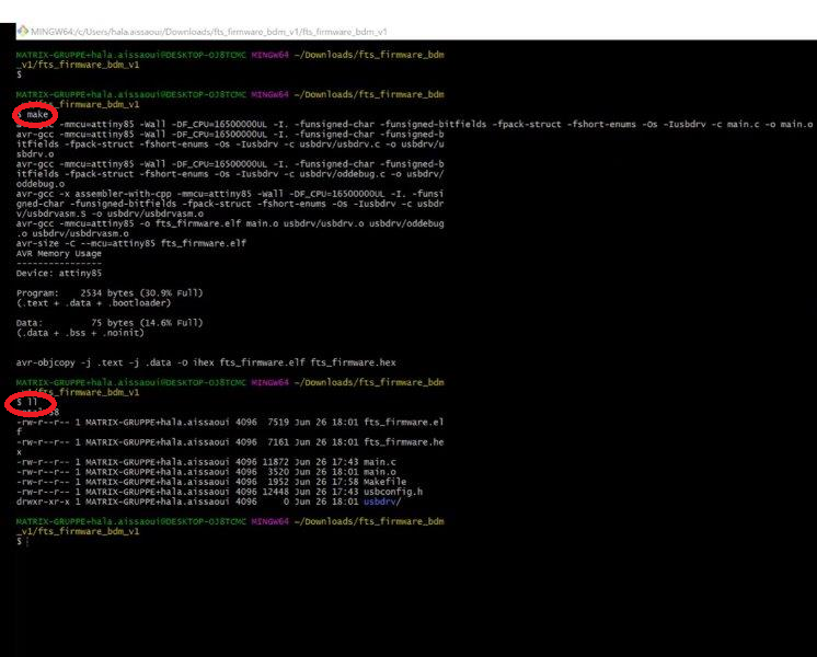
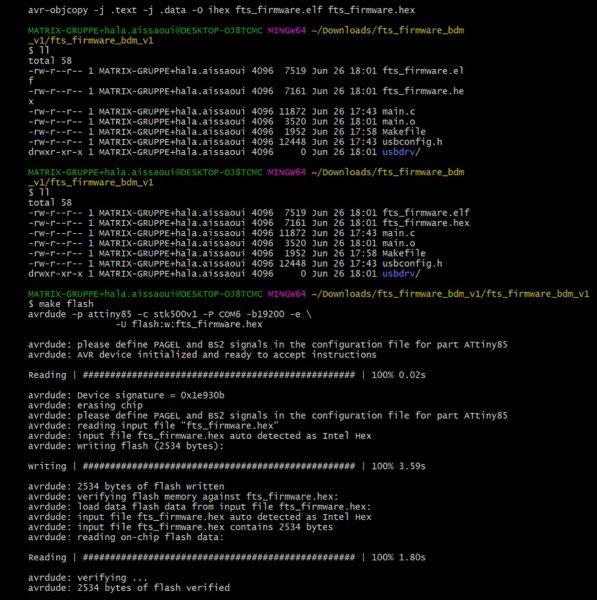
You need o write the two commands LL to check your position and make to check files
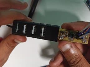
After checking that every thing went alright with the two commands you need to enter new ones but before that, you need to use a USB HUB,to connect your arduino and your ISP together and then to your laptop
Open git and write special commands to program the ISP using arduino
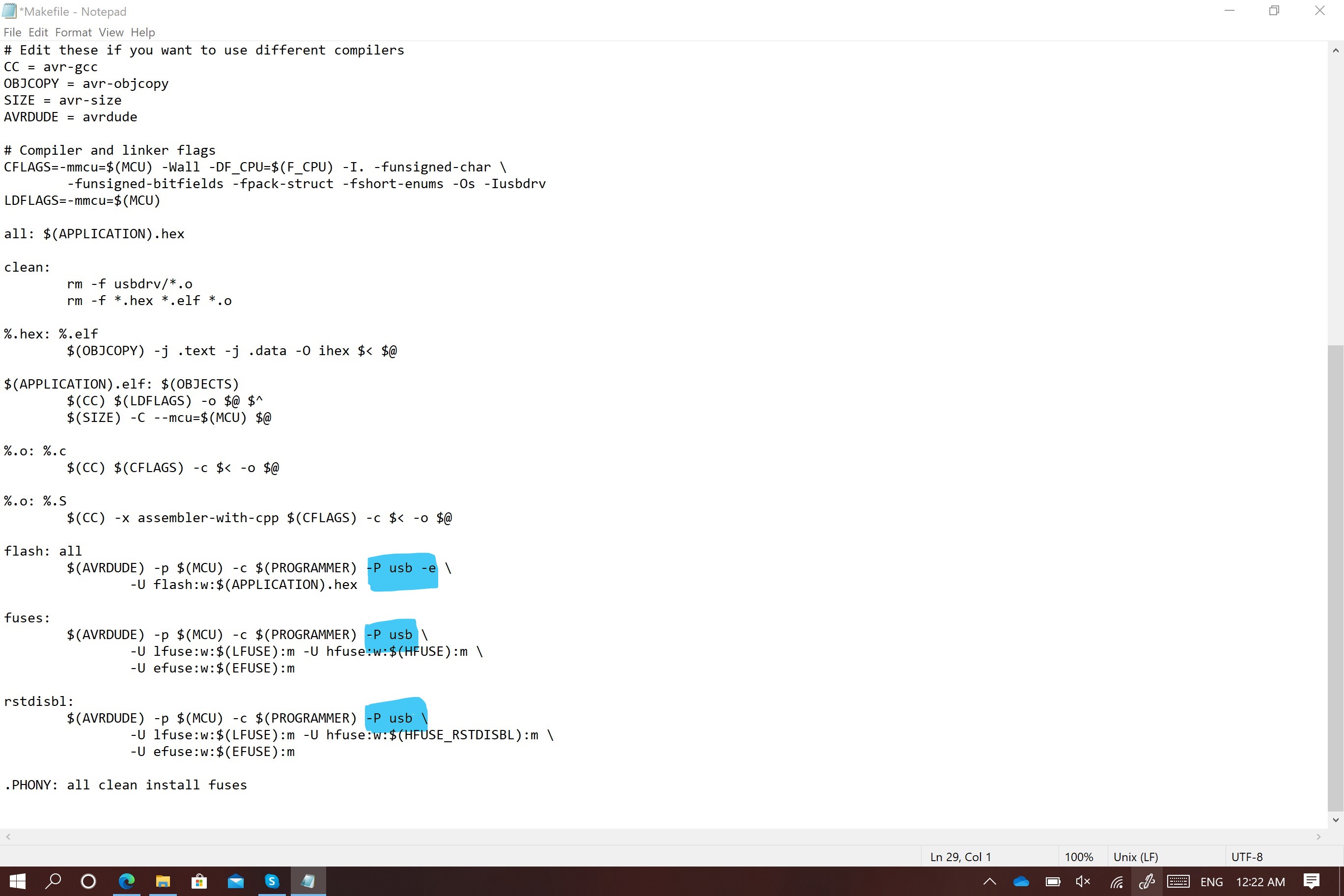
make flash to send tje code to program the ISP
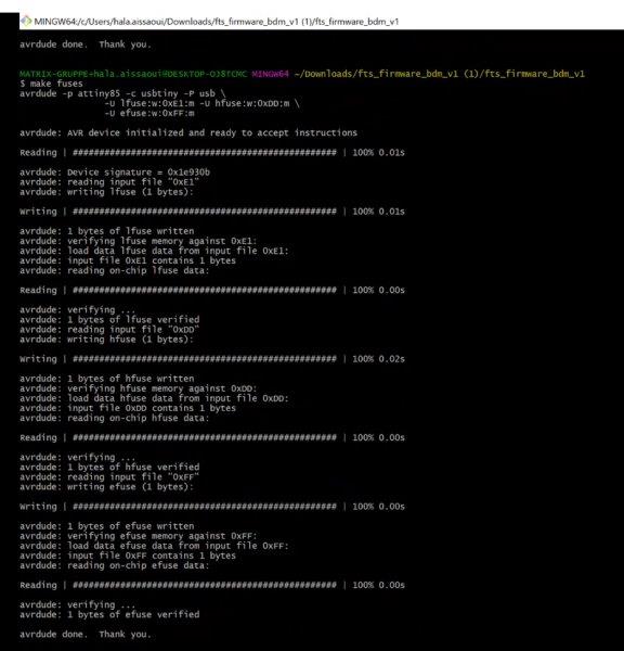
make fuses to upload settings
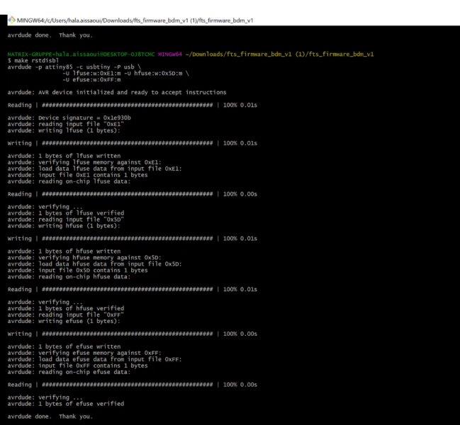
make rstdisbl to disable one of the pins to work as a reset
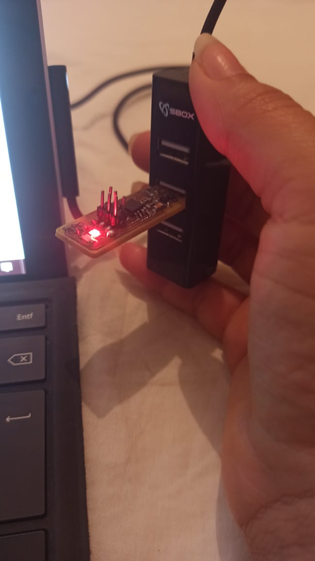
You see your ISP LED blinks so you can confirm partially the ISP programming ,
and yes the LED lights so i felt a little bit sure that i did the steps correctly .
Now Disconnect your arduino from the USB hub as well as all the jumper cables and keep only the ISP connected
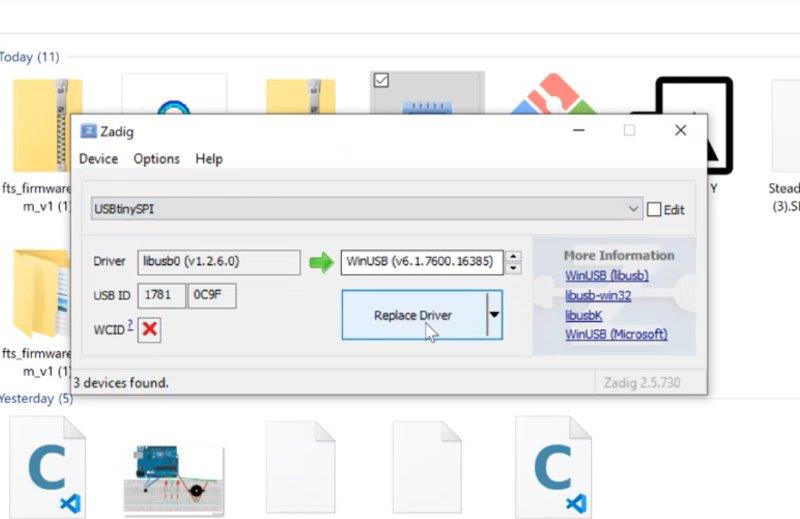
Use the Zadig software to instal the driver for the ISP
It can makes some time but it works at the end :)
1- Search for USPtinySPI
2- Click on Install Driver
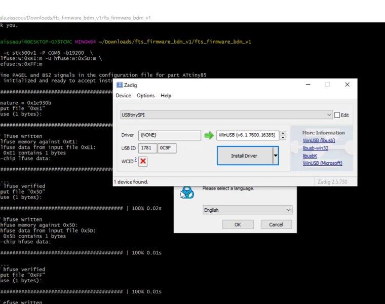
nowthe driver is installed so the Fab isp is well programmed
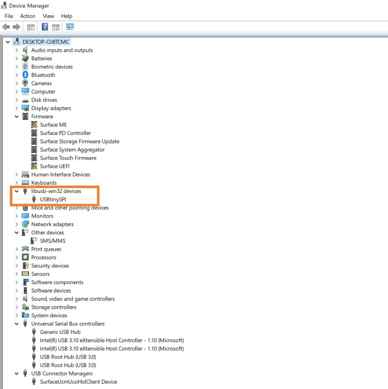
to check if the ISP driver is installed you can go to
device manager->libsub-win32devices and find USBTINYSPI
so we finished our first programming board ISP using the arduino
Programm new ISP with my programmed ISP
Now i will use this programmed board to prgram a new ISP
i had to follow same steps as before
Dowwnload the same zip file as for the arduino and my ISP.
extract it and open it’s folder
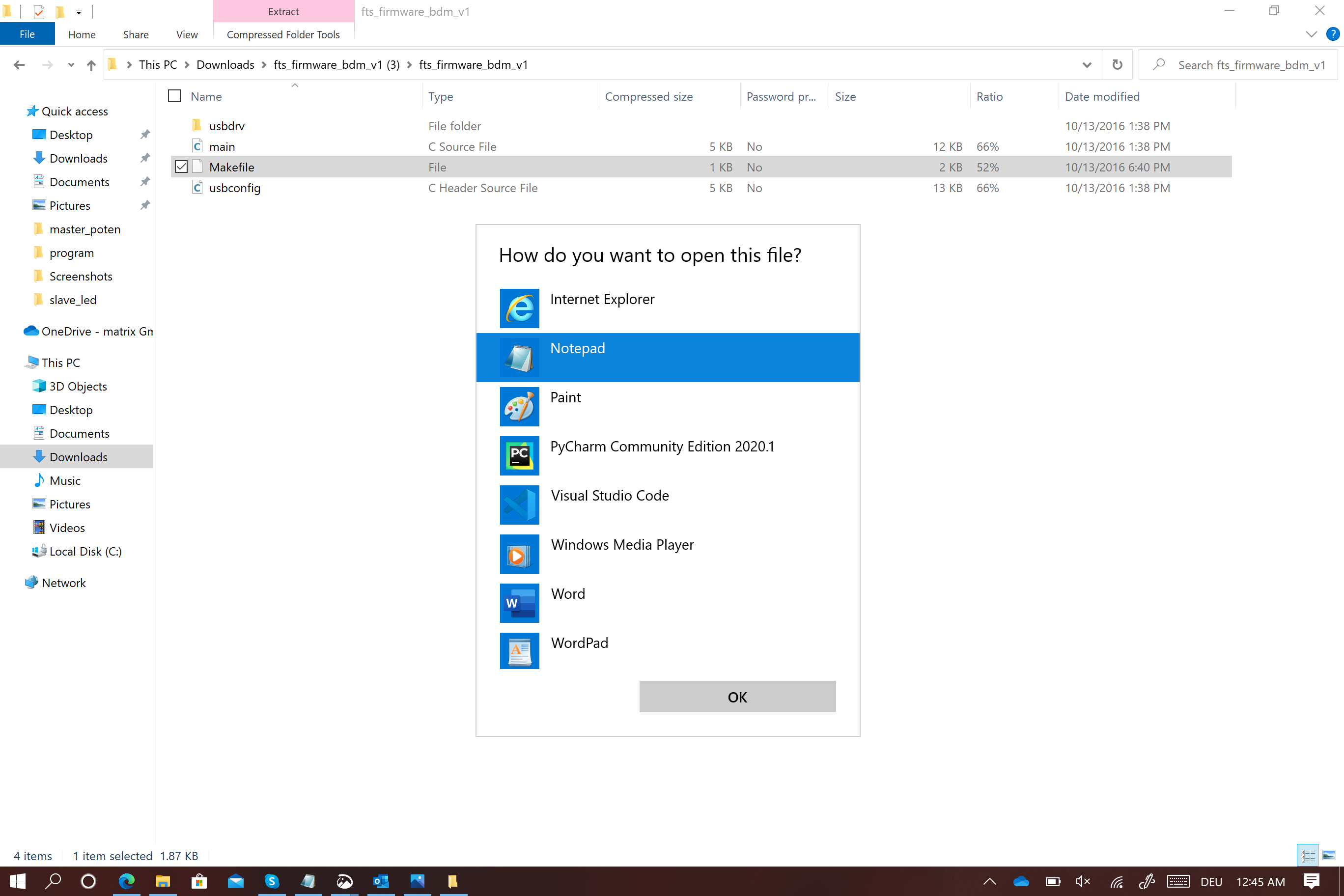
Right click with the mouse on MaKE file and select open with NOTEpad .This time the only change i have to do is
MCU = ATtiny85
Save modifications then connect both of the FAB ISP to the laptop Using the 6 pins isp cable
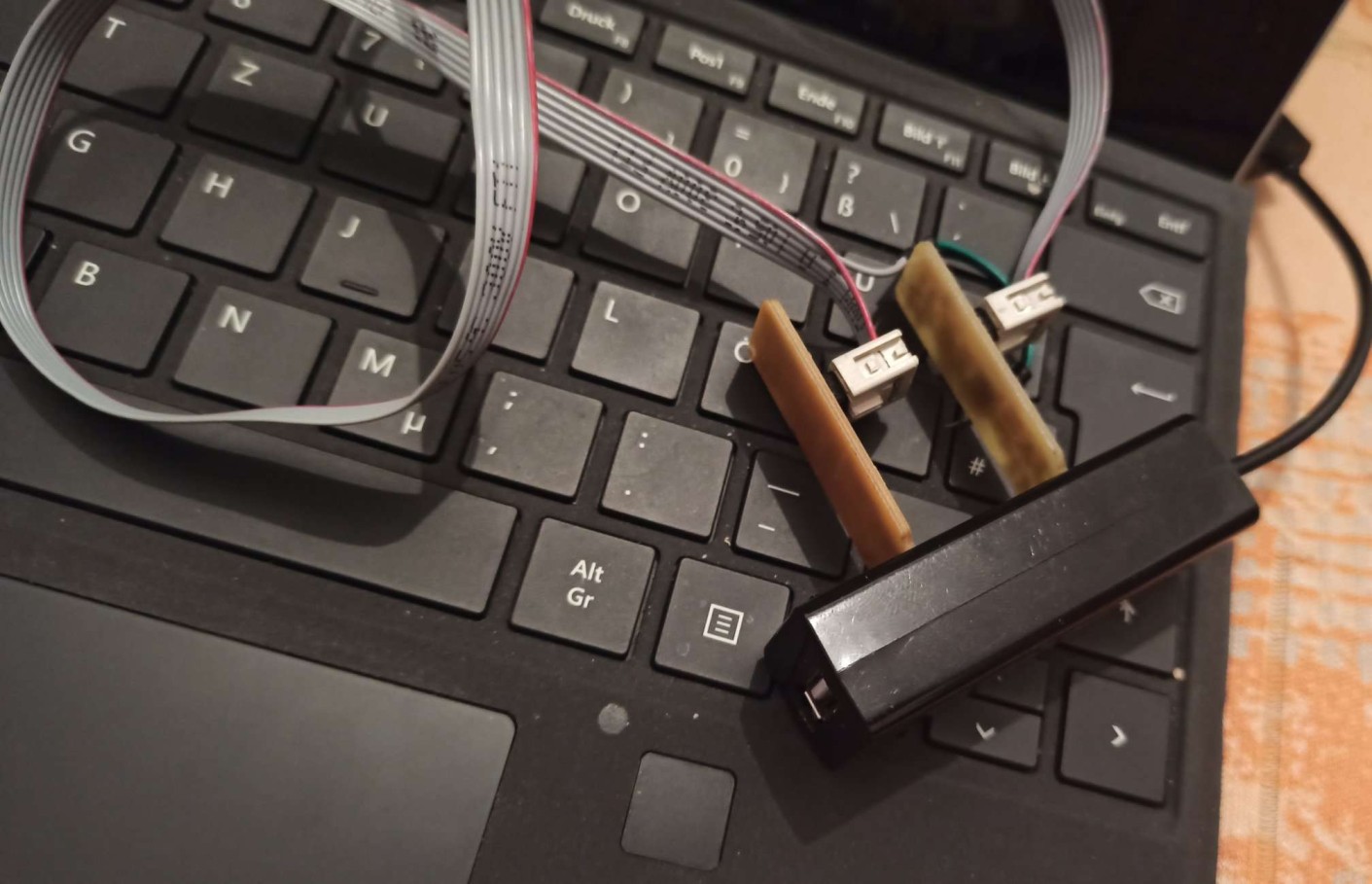
Open the Zip file and right click open git here to write the following commands
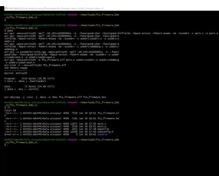
make
ll
make flash
make fuses
make rstdisbl
Go to Zadig and choose USB tiny SPI , this time you don’t have to install the driver , it is already installed
Every thing worked perfectly and i programmed the new ISP