7. Electronics design
Group assignment
Use the test equipment in your lab to observe the operation of a microcontroller circuit board
Individual assignment
Redraw the echo Hello -world board
add at least a button and LED (with current-limiting resistor) resistor calculator
Check the design rules , make it and test it
Group assignment
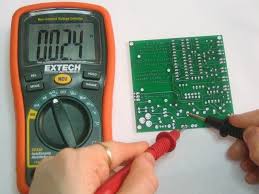
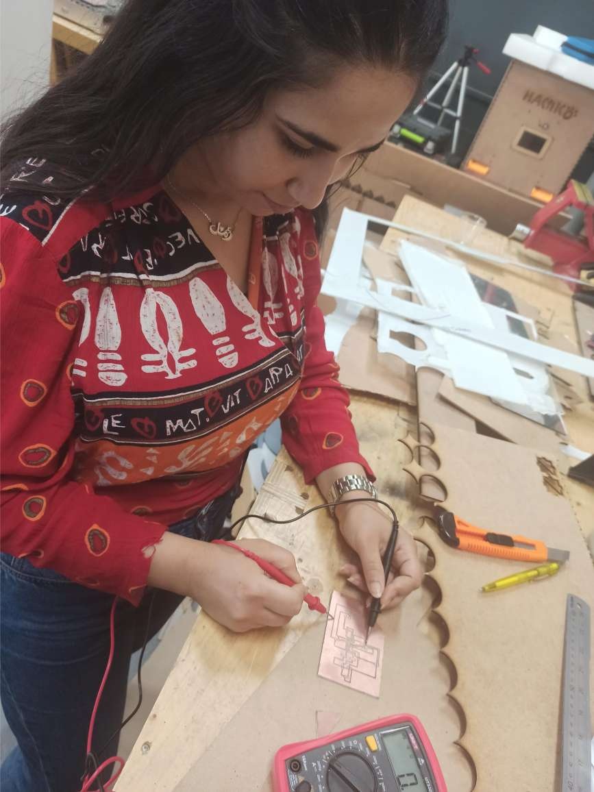
For the group assignment, we had to use an important devices in the lab to test the connectivity among circuits which is the multimeter . This would determine whether we soldered the board correctly or not , so it allows to test the board programing .
You can check this direct group assignment link
Testing Continuity
A continuity test tells us whether two things are electrically connected: if something is continuous, an electric current can flow freely from one end to the other.If there’s no continuity, it means there is a break somewhere in the circuit. This could indicate anything from a blown fuse or bad solder joint to an incorrectly wired circuit.Continuity is one of the most useful tests for electronics repair.
-
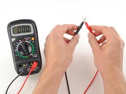
The multimeter tests continuity by sending a little current through one probe, and checking whether the other probe receives it.
-
If the probes are connected—either by a continuous circuit, or by touching each other directly—the test current flows through. The screen displays a value of zero (or near zero), and the multimeter beeps. Continuity!
-
If the test current isn’t detected, it means there’s no continuity. The screen will display 1 or OL
## Individual assignment
Echo-Hello Board
This board uses an ATTiny44 microcontroller, an FTDI connector, a 6-pin ISP Header, two 10kohms resistors, a 20MHz resonator and a capacitor 1uF . I’ve also put a button and an LED to program the board that ‘s why i added a 499 ohm resistor
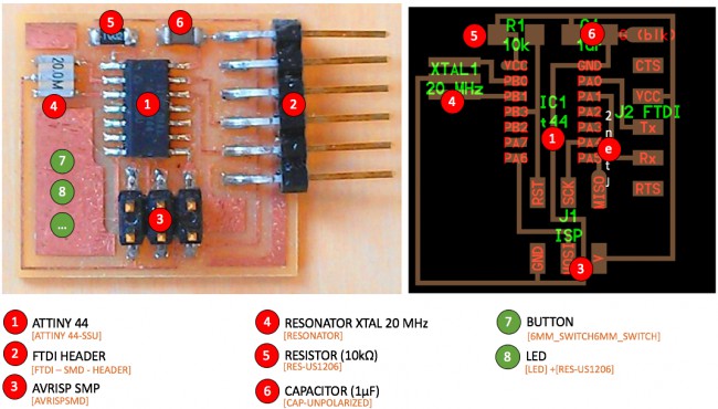
- ATTinny44 microcontroller: This high performance, low power AVR 8-bit microcontroller is perfect for simple boards. The CPU must be able to access memories, perform calculations, control peripherals, and handle interrupts. The on chip ISP Flash allows the Program memory to be re-programmed in-system through an SPI serial interface most commonly.
PCB Design
I have never used a PCB Design software,but after an introduction to Autodesk Eagle from the instructor I could draw my PCB taking the ‘Hello World Board’ as a reference.
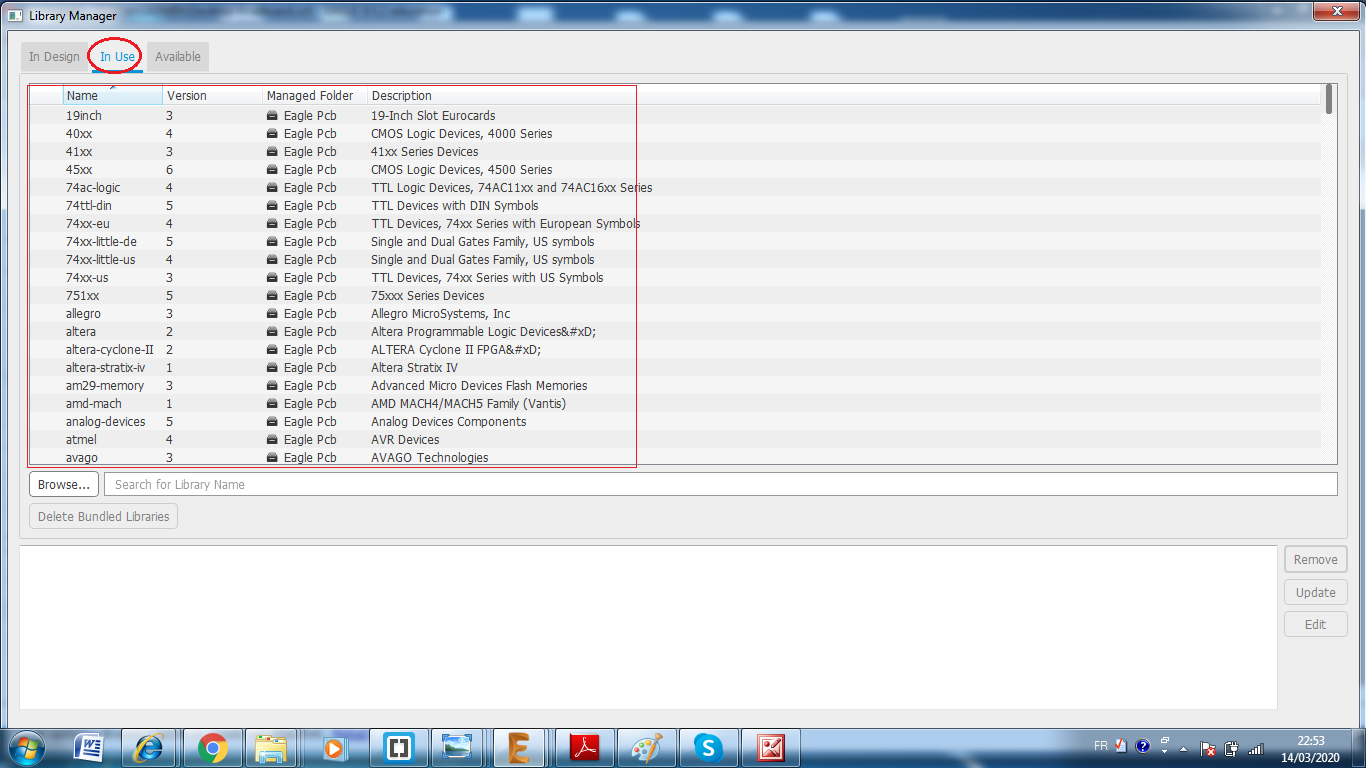
I started by Downloading FAB components Library
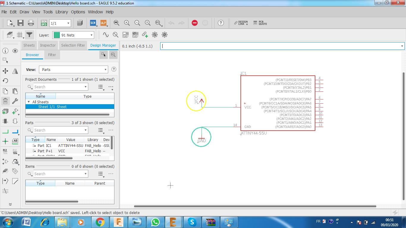
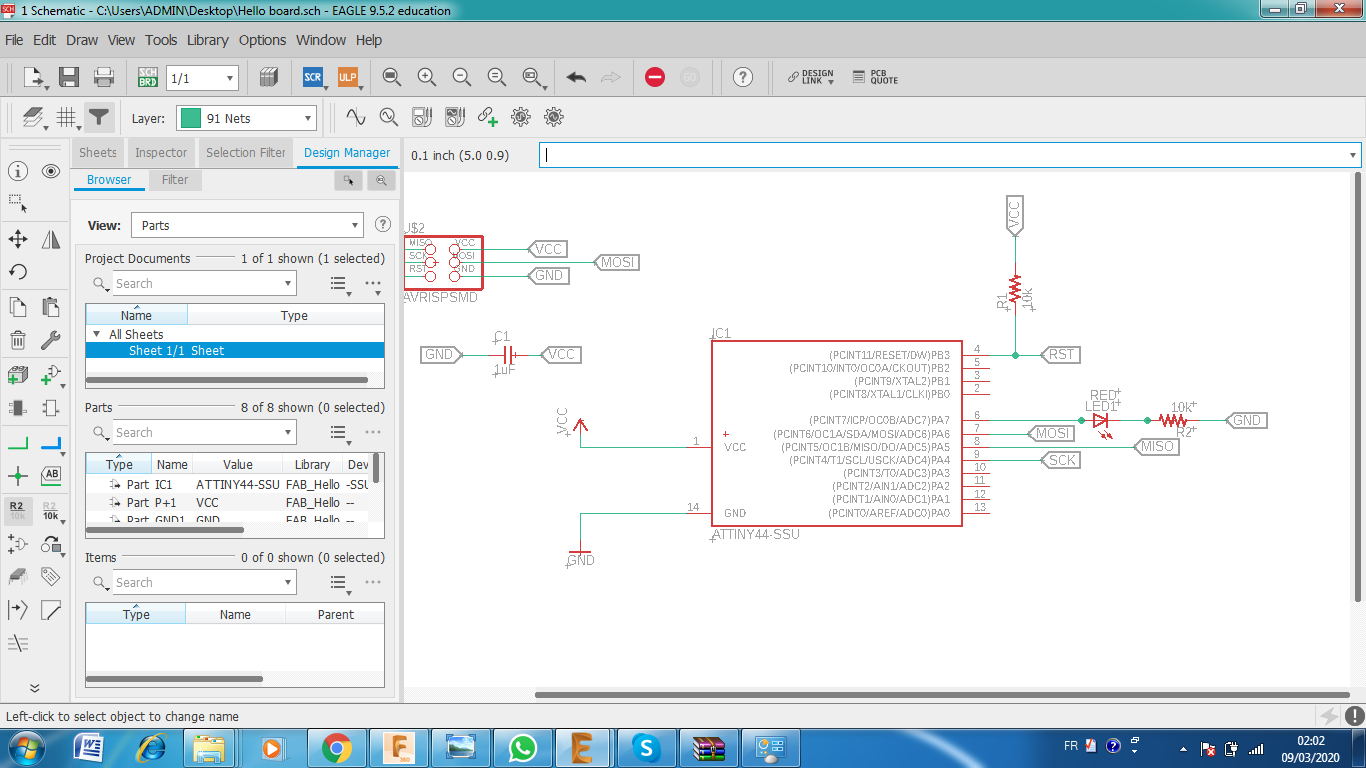
After downloading the library , you need to open both ‘Schematic’ and ‘Board’ windows on Eagle to work on. Then search and place the components on ‘schematics’
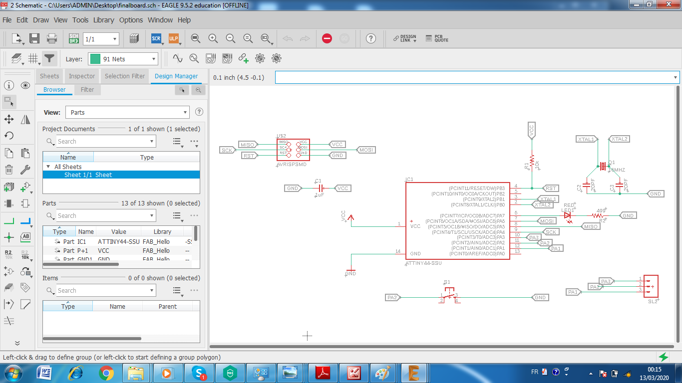
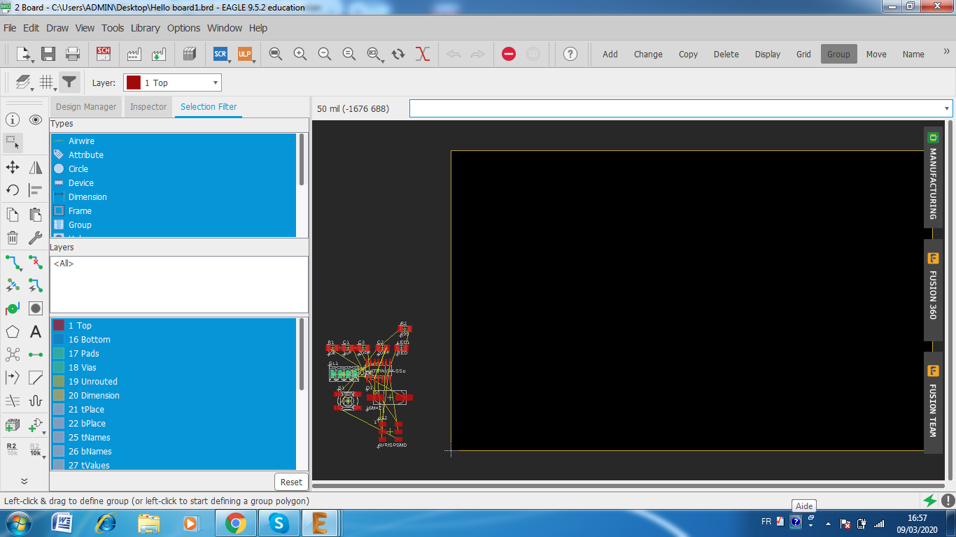
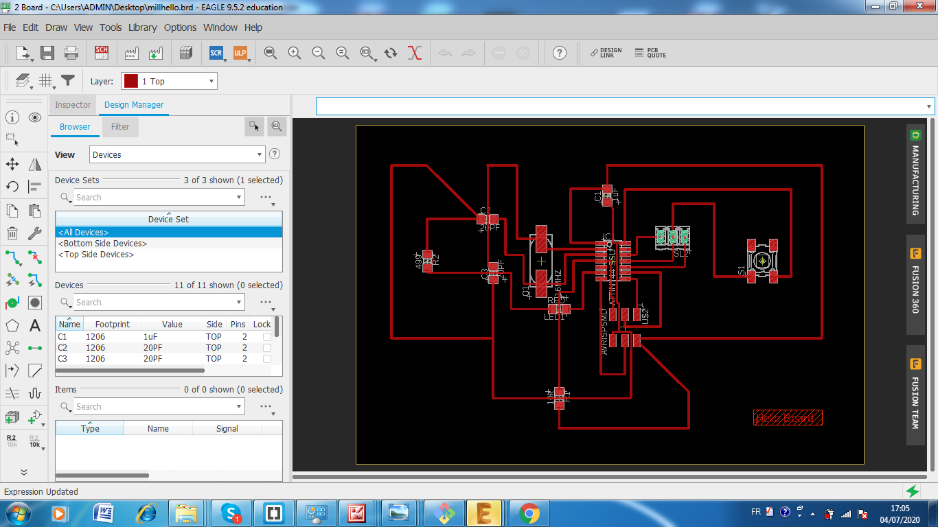
After finishing the schematic I switched to ‘Board’ window, and it should show up like this
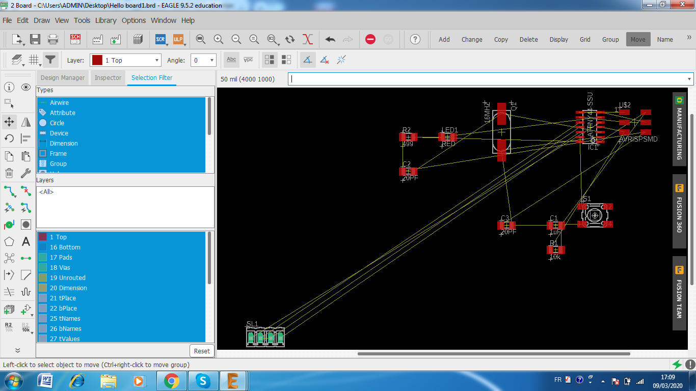
I started moving components in their places .Routing the connections wasn’t really easy because sometimes the software shows impossible paths .At the same time eagle can facilitate the work when you need just to replace the automatic paths in yellow.
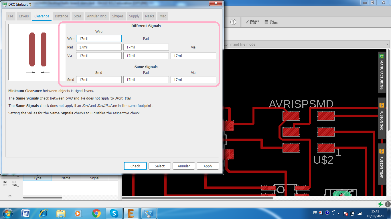
A group of design rules that help you with some things like the minimum clearance between components. You can add it in the Tool menu > DRClike showing bellow
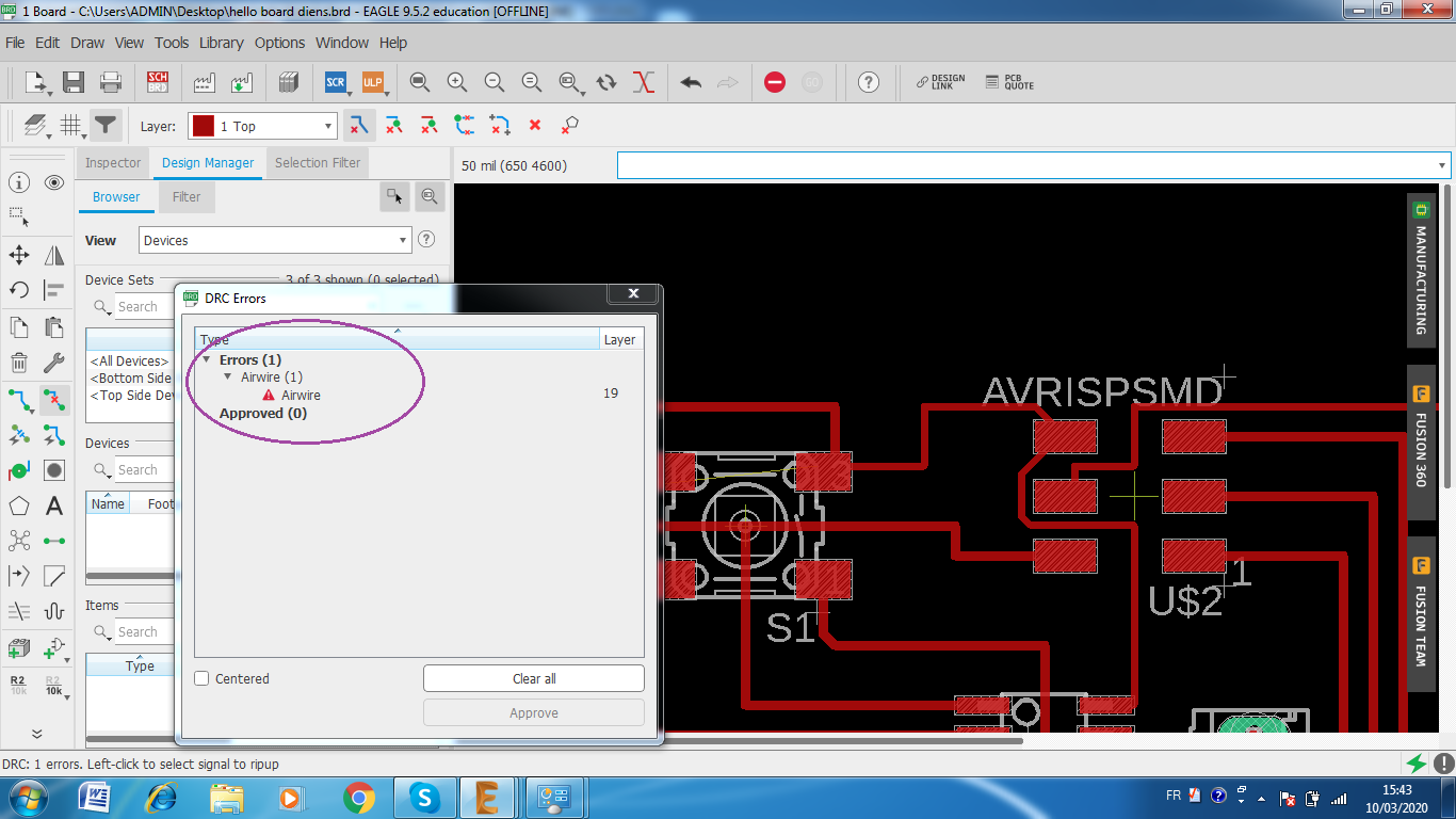
After finishing my PCB design and correcting the errors , I sent the model to my instructor to check it for me , so he advised me to use only 45°and 90°traces to make the board layout more organized
Here you can download the Eagle schematic and The eagle board
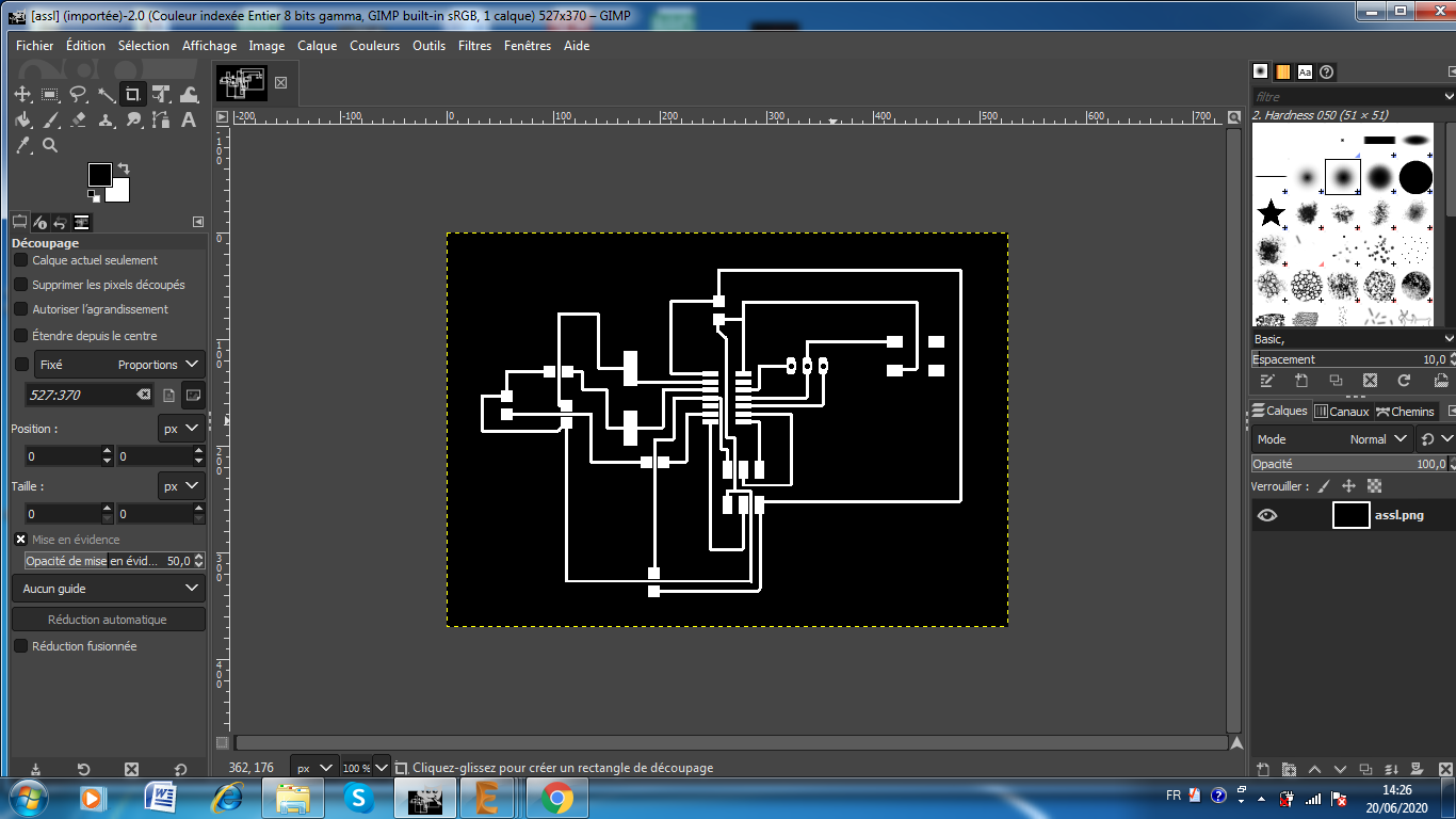
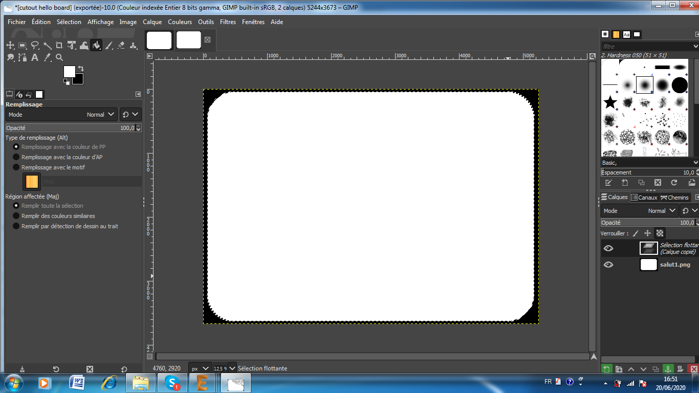
Export the document as a png image, with 500 dpi and in ‘Monochrome’.I used gimp software to make a cut out for the board
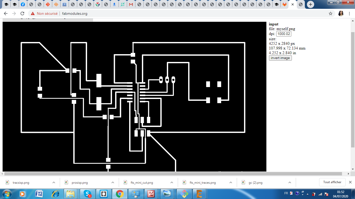
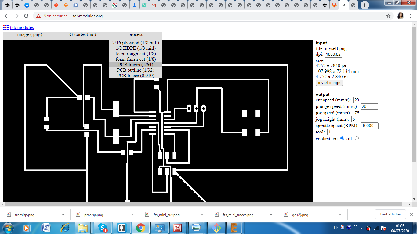
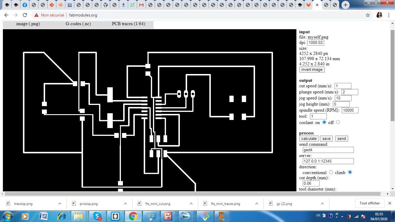
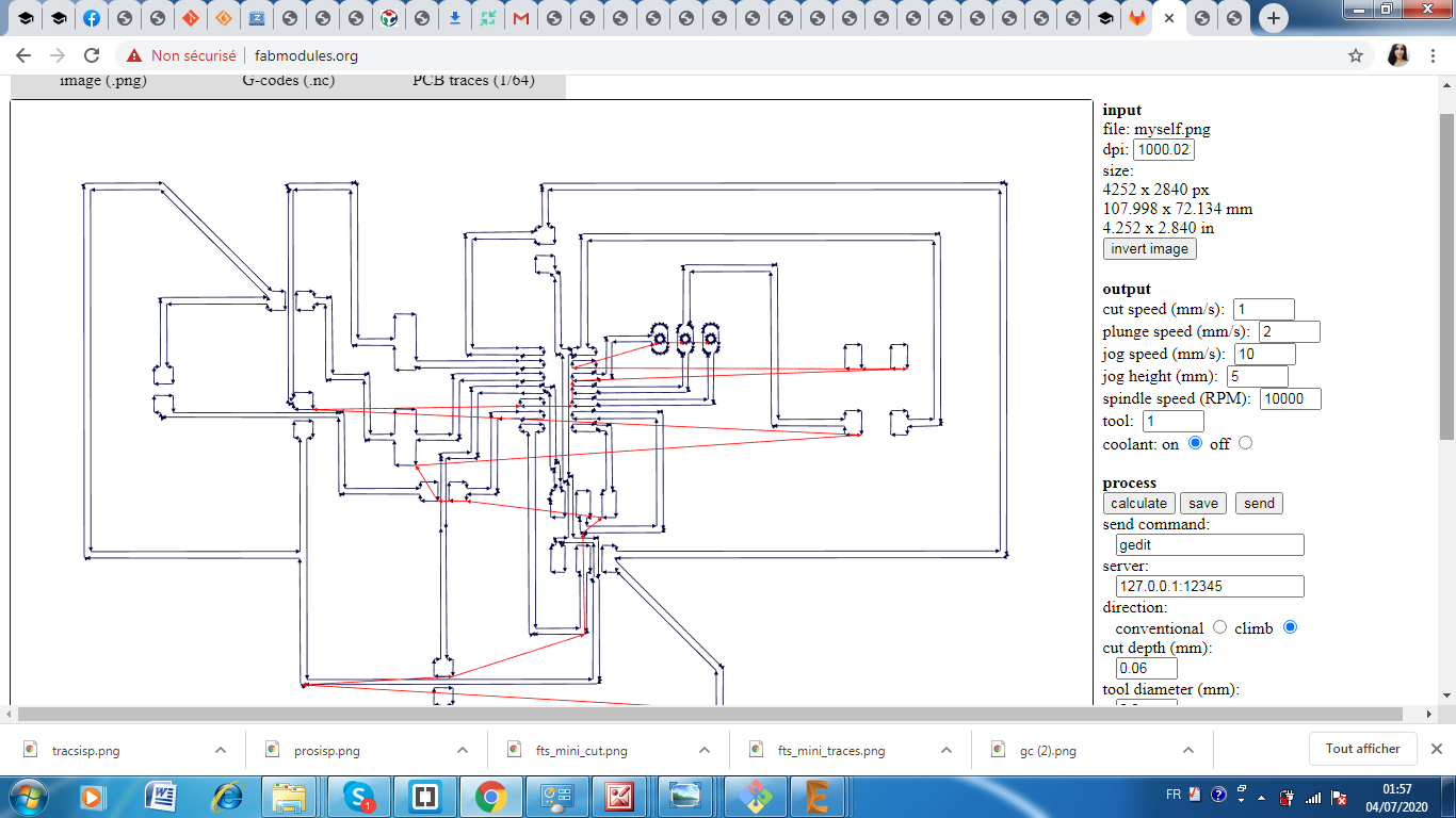
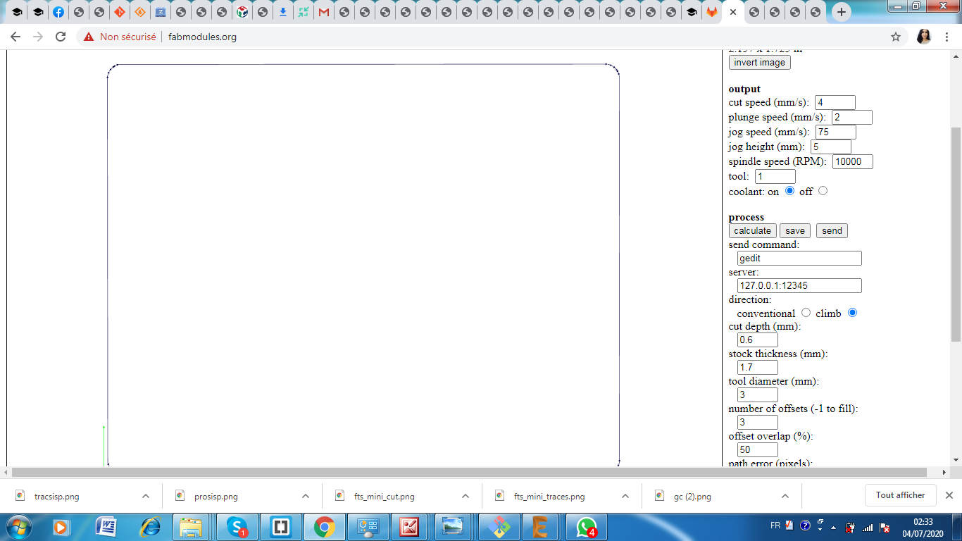
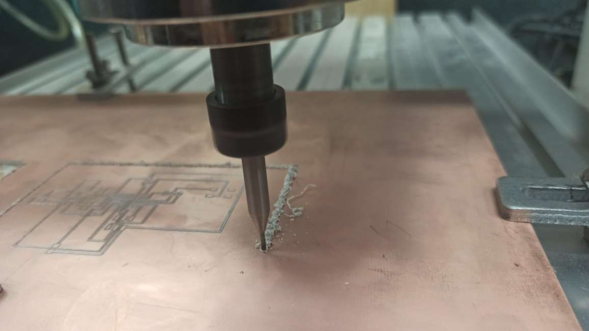
I used Fabmodules online at FabModules to upload the .png images successively and to generate the G-code for the CNC mill to mill the traces and to mill the outline shape of the PCB.
Here you can download png files for the hello traces and the the hello cutout
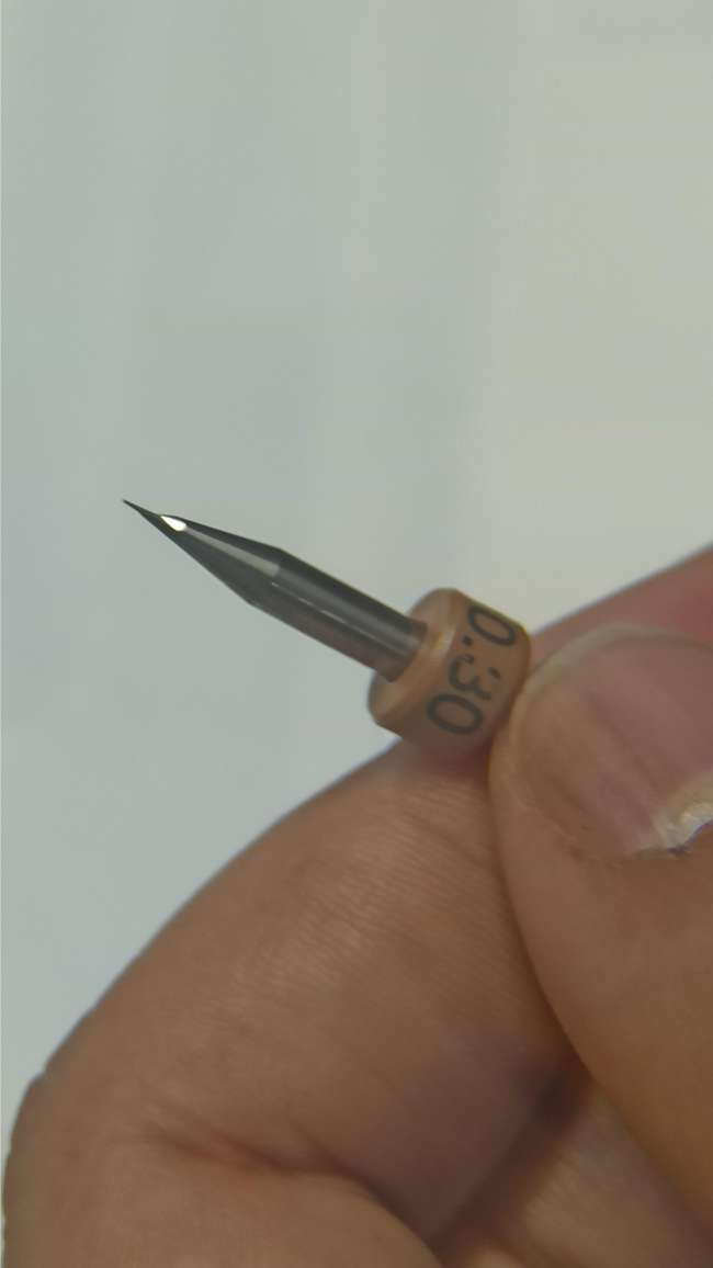
Prepar the machine and choose the right tool
It is a very important step to make the milling goes sucessfully so i used double sided tape to fix my piece of copper on the machine bed.
then i mounted my mill bit carefully in the collet. I started moving the machine to the start point using “X min, Ymin” and “Move to Xmin and Ymin” features. i did Zero for Z axis, and this is by moving the machine to the bottom carefully using the down button.
for accomplishing the following operation without risk of damaging the drill tip,you have to lower manually (slowly and by heavily controlled steps!)
When you are close to the copper sheet (around 0.5 mm), loosen the mill bit and allow it to slip slowly till it touches the surface of the copper. Now the last step is to choose the G code that you have already prepared and send it !
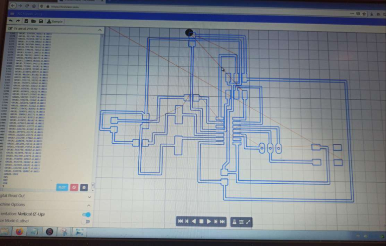
Before sending the code i used a software called ncviewer to check if the G code is well saved and well generated
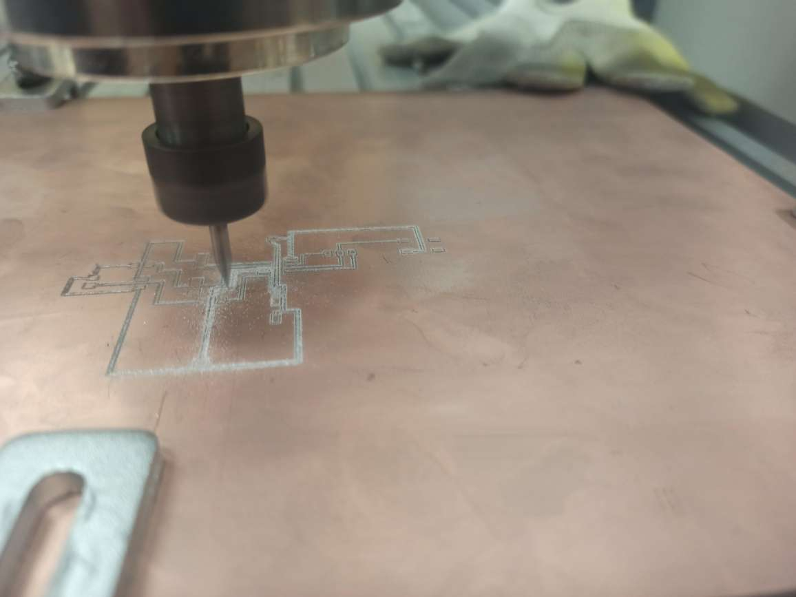
I finished my hello board milling and it looks god so far
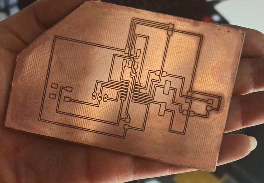
Now i had to test the connectivity among circuits with the multimeter . This would determine whether i soldered the board correctly or not
Connectivity seems good so It is time to solder my components !!!
Here it is the list of the required components
Capacitor 20pF x2
Capacitor 1uF x1
Crystal 16MHz x1
ATTiny84 x1
Red LED x1
Pushbutton x1
2x3 pin header x1
1x3 pin header x1
Resistor 499 x1
Resistor 10k x1
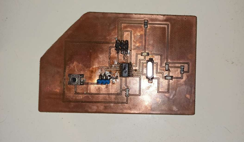
I felt more comfortable with soldering this time because i learnt from my ISP soldering the last time
I think the result is not bad :)
Programming
After finishing the mill and the soldering , i need to program my Hello board
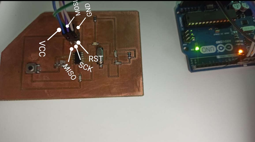
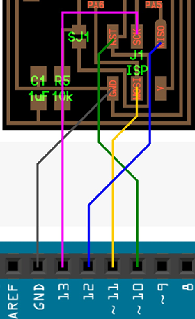
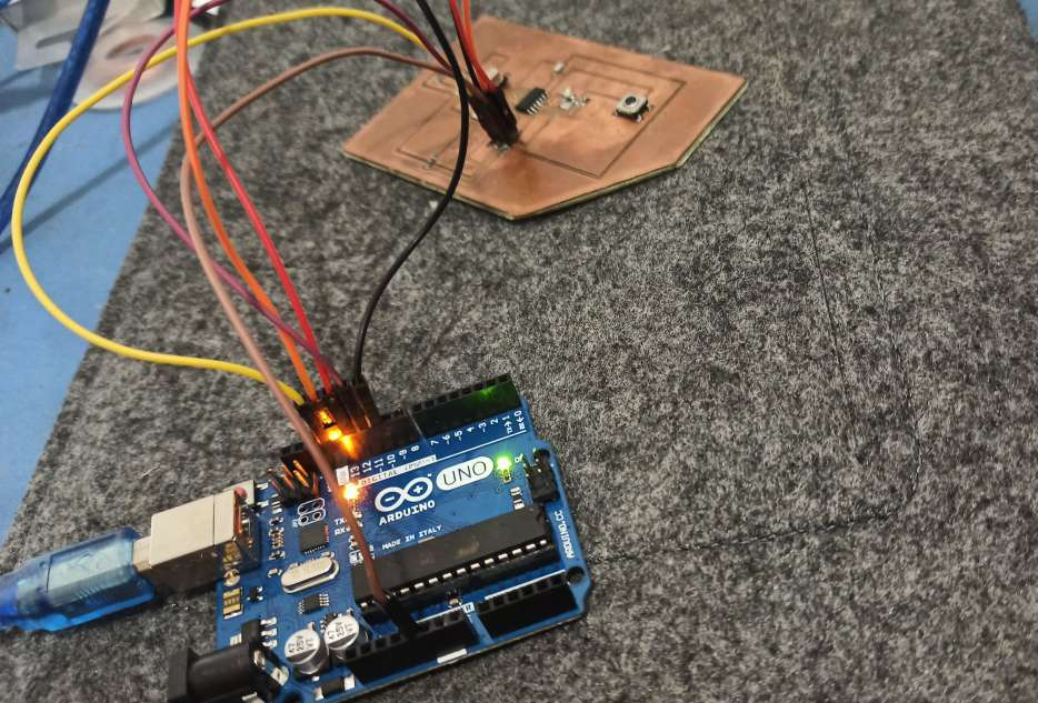
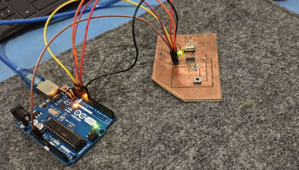
First i had to connect the Hello Board to the arduino as showing bellow
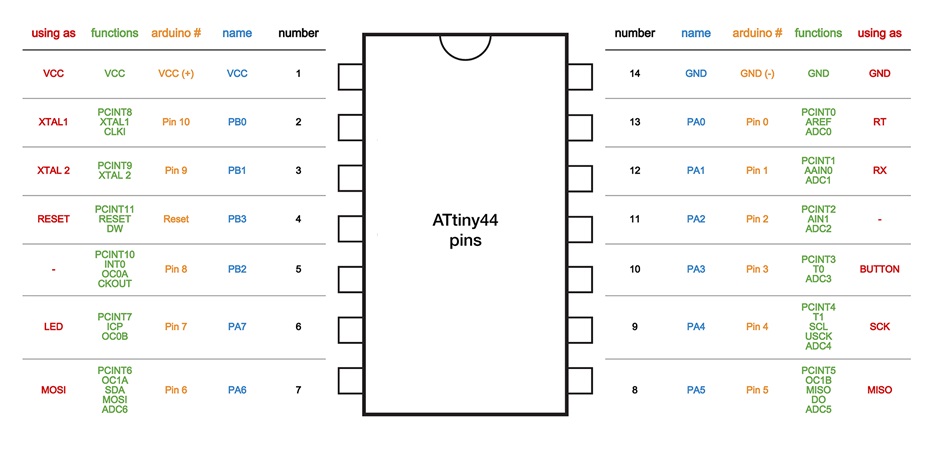
I identified my pins so i can connect them correctly to the arduino
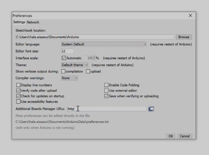
Then i need to modifie the arduino IDE to make it able to work with Hello board , to do that
I had to open this link and then copie it in the arduino preferences as showing bellow
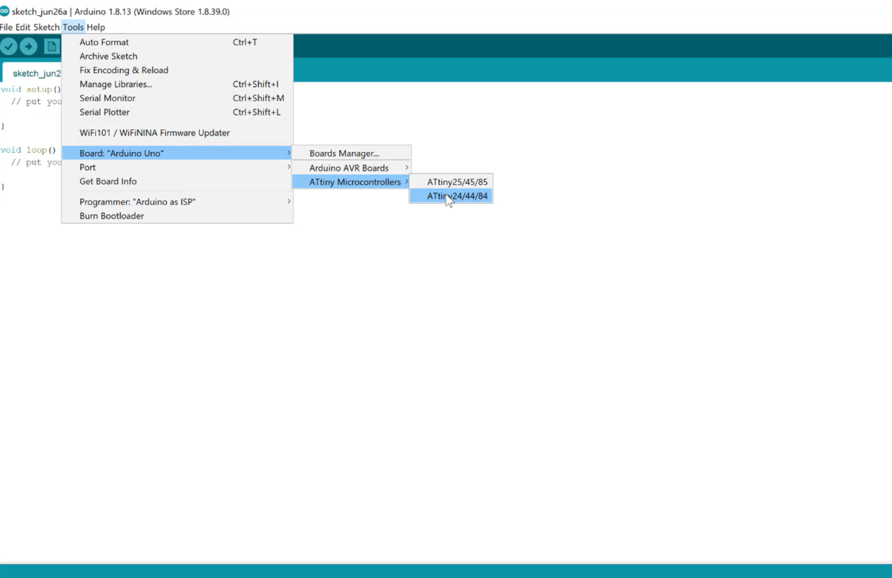
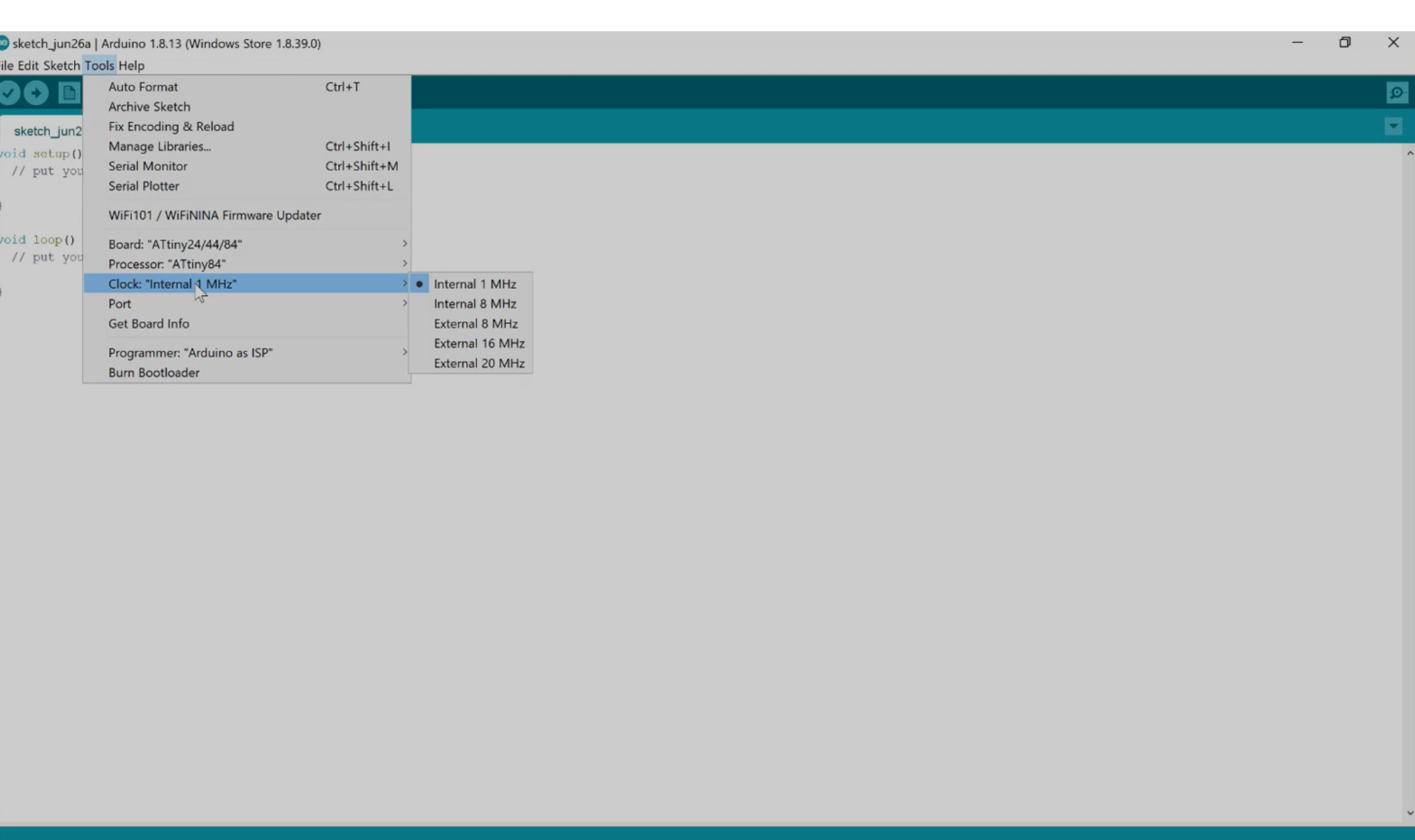
Now i m able to select my aTtiny microcontroller which is ATtiny 84
After that i had to click tools and choose External16mhz
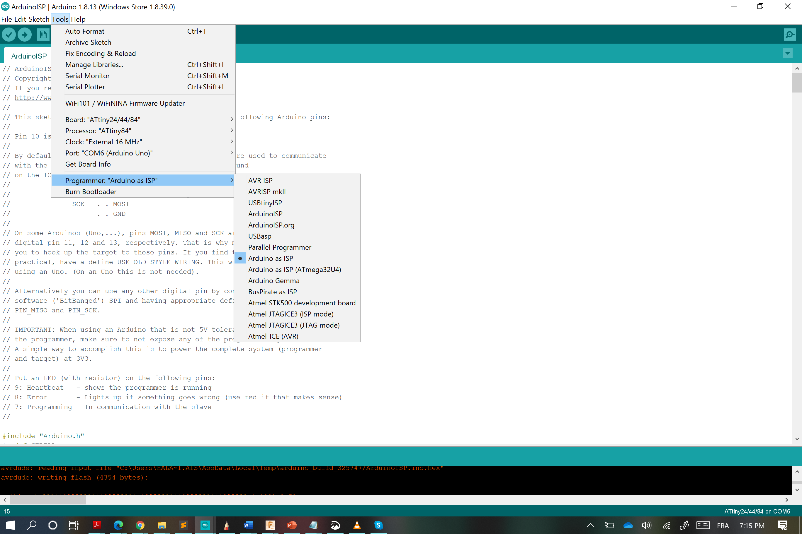
I had to choose the programmer which is Arduino ISP
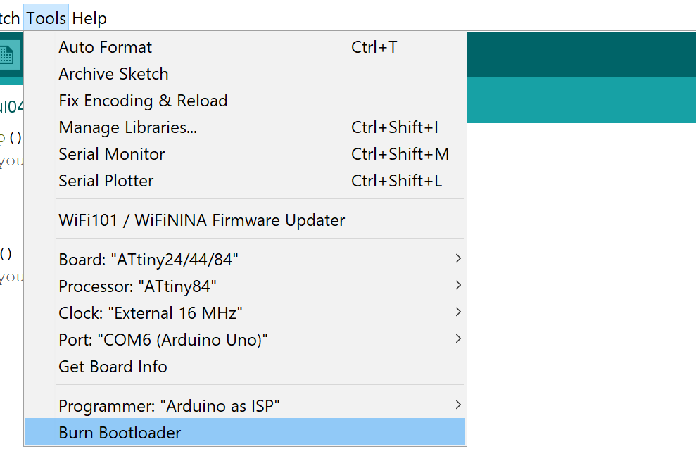
The next step is to burn Bootloader , if every thing is all right , it will be done successfully
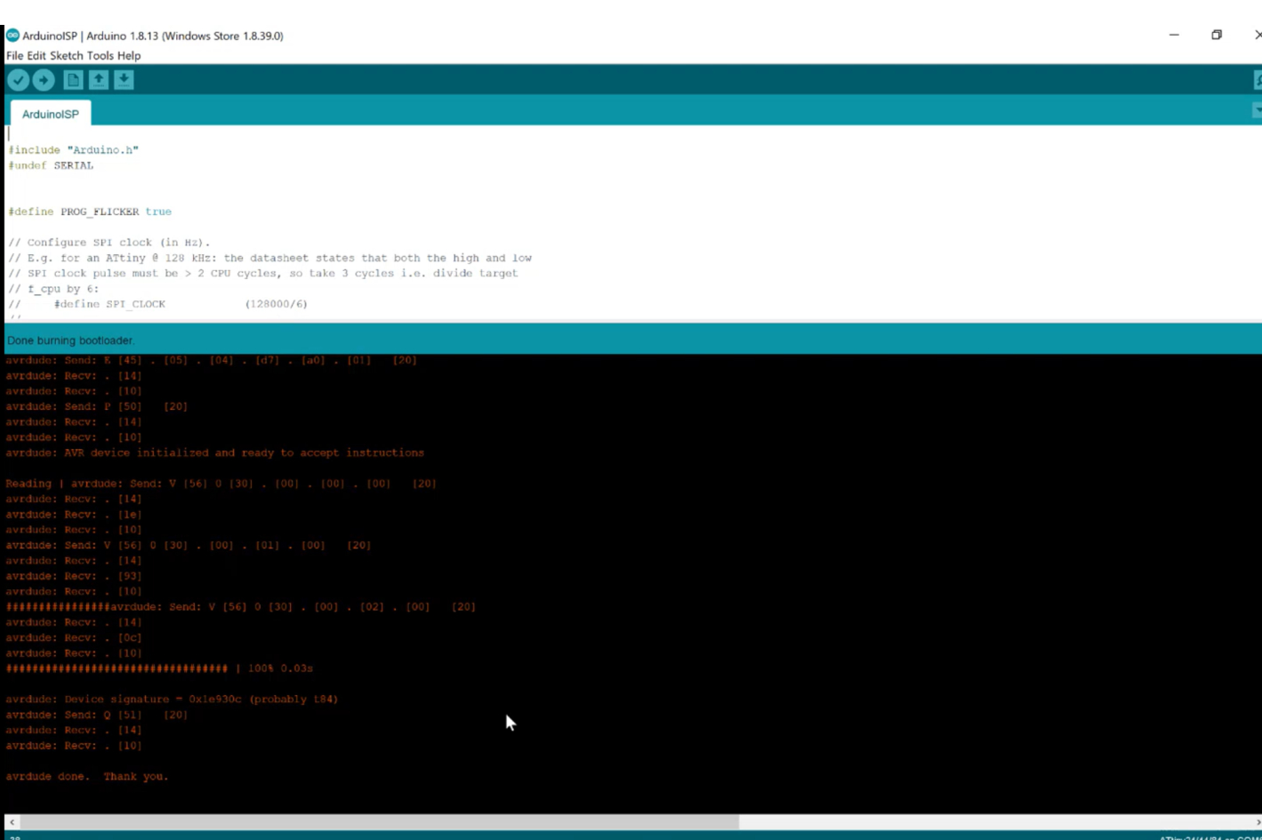
and yes !! Done burning bootloader
Now i need to blink the Hello board LED , so i need to choose from basic examples the blink code and uploasd it using programmer
It was the moment of truth XD , if i did the previous steps perfectly the LED will blink
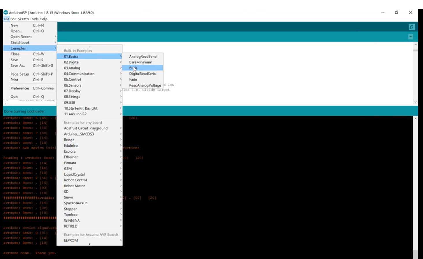


I guess i did it well beause theLED is blinking :)
Check this video