6. 3D Scanning and printing
This week I worked alongside my group to test the design rules for our 3D printer. In addition I designed and 3D printed an object that could not be made subtractively and 3D scanned an object.
3D printing
3D printing or additive manufacturing is a process of making three dimensional solid objects from a digital file.
It enables you to produce complex shapes using less material than traditional manufacturing methods .
The creation of a 3D printed object is achieved using additive processes. In an additive process an object is created by laying down successive layers of material until the object is created. Each of these layers can be seen as a thinly sliced horizontal cross-section of the eventual object. 3D printing is the opposite of subtractive manufacturing which is cutting a piece of metal or plastic with for instance a milling machine.
3D printing material
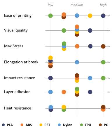
Many different materials can be used for 3D printing, such as ABS plastic, PLA, polyamide (nylon), glass filled polyamide, stereolithography materials (epoxy resins), silver, titanium, steel, wax, photopolymers and polycarbonate .
-
PLA is the easiest polymer to print and provides good visual quality. It is very rigid and actually quite strong, but is very brittle.
-
ABS is usually picked over PLA when higher temperature resistance and higher toughness is required.
-
PET is a slightly softer polymer that is well rounded and possesses interesting additional properties with few major drawbacks.
-
Nylon possesses great mechanical properties, and in particular, the best impact resistance for a non-flexible filament. Layer adhesion can be an issue, however.
-
TPU is mostly used for flexible applications, but its very high impact resistance can open for other applications.
-
PC is the strongest material of all, and can be an interesting alternative to ABS as the properties are quite similar.
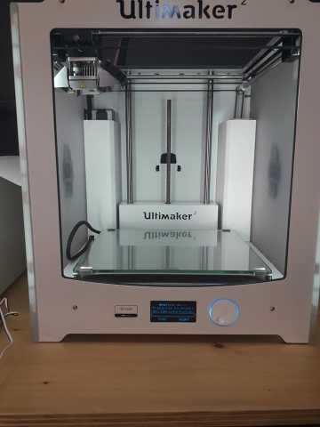
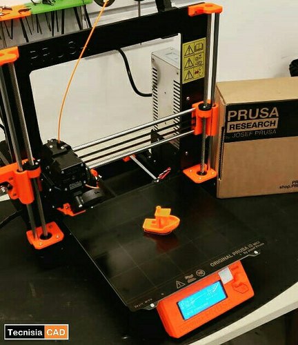
3D printing machines
There are several different kind of 3D-printing machines ,However in Our Fab Lab we have three kind of machines
Group assignment
Here you an check the group assignment link
Testing printer
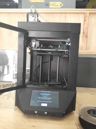
To test the different printers, we have printed first model by the Raise 3d n1.
Raise 3d n1 propreieties
Print technology: FDM (FFF)
Build Volume (WxDxH): 8x8x8 inch / 205x205x205
Layer Resolution: 0.01-0.25 mm
Filament Type: PLA/ PLA+/ ABS/ PC/ PETG/ R-flex/ TPU/HIPS/ Bronze-filled/ Wood-filled
Printing Surface: Buildtak
Heated Build Platform: Yes
Enclosure: Yes
Nozzle Diameter: 0.4 mm (0.016 in)
Nozzle Working Temperature: 170-300 ℃
Number of Nozzles: 1 (standard) / 2 (optional)
Printing Speed: 10 ~ 150 mm/s
Moving Speed: 150 ~ 300 mm/s
Positioning Accuracy: XY-axes: 0.0125 mm, Z-axis: 0.00125 mm
To do this, we’ve used a file available on thingiverse
This article explains what should be measured as pointed below:
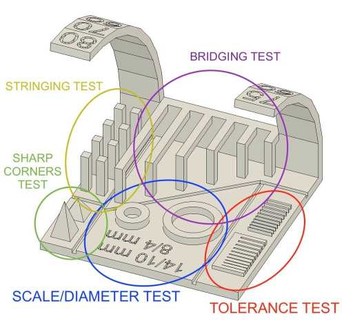
bridging test
Bridging is your printer’s ability to print a layer between gaps in lower layers without support, essentially printing over thin air, creating a “bridge”
Stringing test
3D prints sometimes show small strands of plastic on places where the printer shouldn’t print and the print head must only travel from one place to another. These unwanted strands of plastic is called stringing
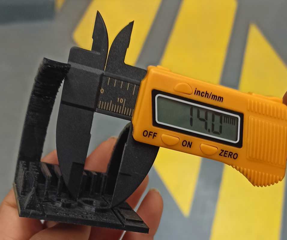
Tolerance test
It describes how much deviation from a particular value is expected or acceptable. In 3D printing, like any other manufacturing process, machines have specific tolerances. This means that prints may slightly deviate from the actual dimensions. A tighter tolerance indicates consistently higher dimensional accuracy
Overhang test
In general, when your model has an overhang or a bridge which is not supported by anything below, you may need to use 3D printing support structures to be able to 3D print it.his test aalows us to define the ability of the 3d printer to make overhangs without support .
To test the design rules of our 3d printer we have fixed the following measurements
 *  Hole size: 2 holes (8/4/mm) (14/10/mm)
 * Tolerance test : 0.05/0.1/0.15/0.2/0.25/0.3/0.35/0.4/0.45/0.5mm
 *  Bridges length : 2/5/10/20/15/20/25 mm
 * Overhang : 10°/15°/20°/30°/40°/45°/50°/60°/70°/75°/80°
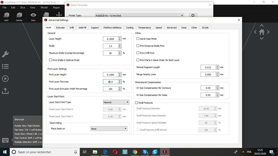
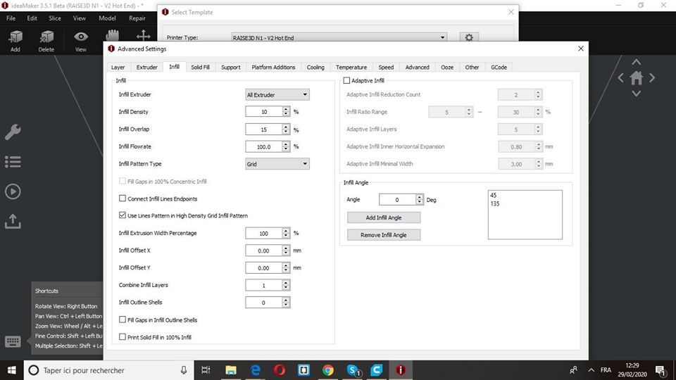
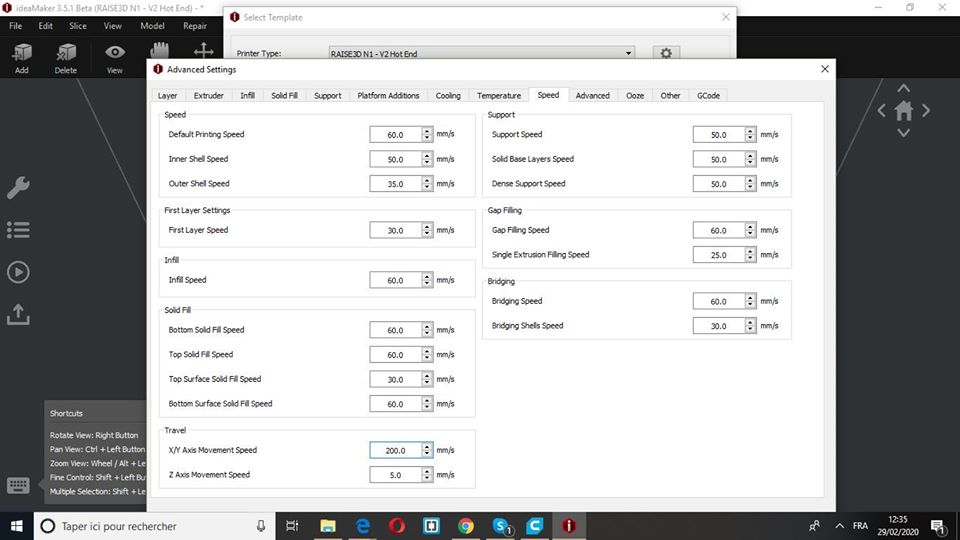
Slicing settings
Layer height: 0.1mm
Shels: 1
Infill: 10%
Speed: 60mm/s
Nozzle temp.: 205
Bed temp: 60
Material: PLA
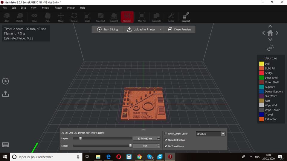
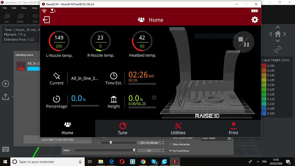
Printing process
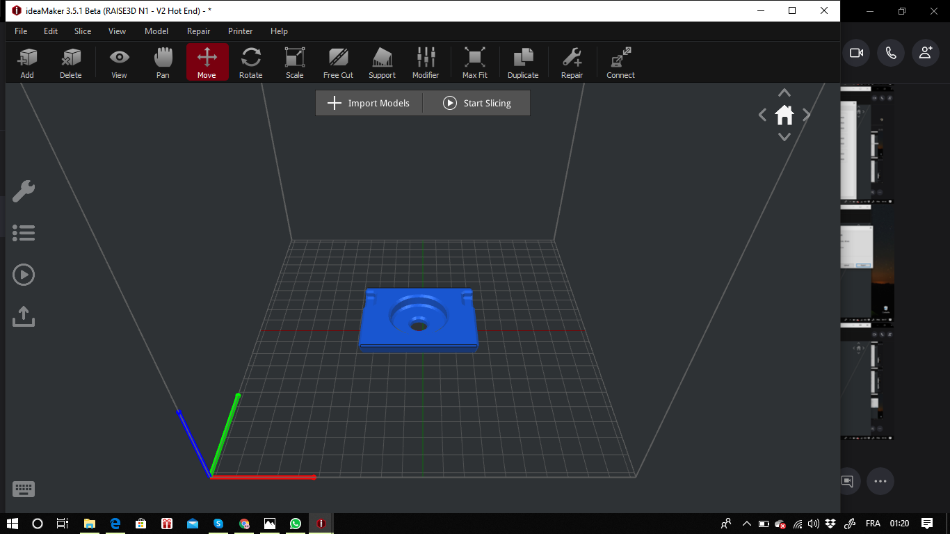
For the printing process, we will need to import the .stl file with the proper software, In our case we used idea maker for (Raise 3d n1).
Testing results
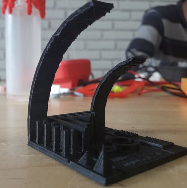
These are the results of the testings:
Raise 3d n1
Results
Overhang : Up to 45 º
Stringing : No unwanted strands of plastic
Bridges: We got perfect bridges up to 25mm without a support
Tolerance test: We coudn’t have same dimensions , however we had a similar tinny parts measured around 0.4mm . It’s explicated by the fact that the machine is able to make multiplication measures of the nozzle dimension (0.4mm)
Scale test: We obtained same dimensions as measured
Individual Assignment
Modeling
1.Fusion 360
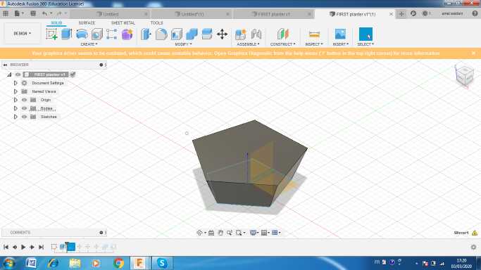
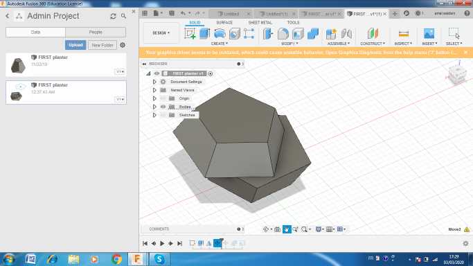
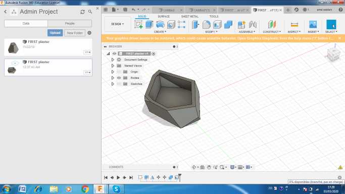
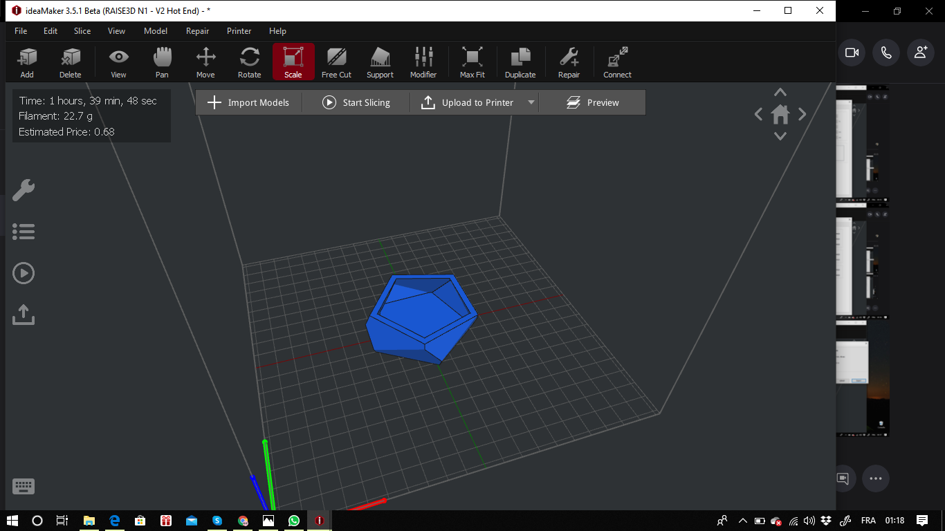
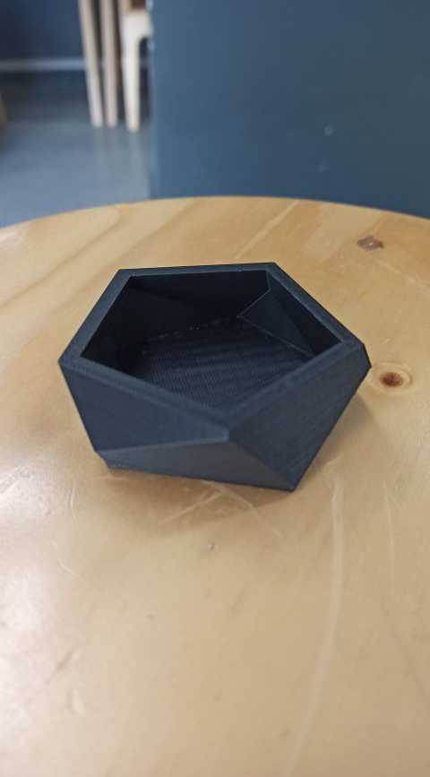
I created a geometric planter on fusion 360 following these steps
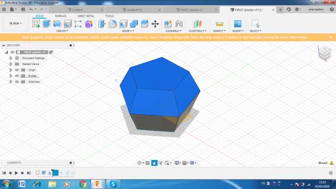
I started by creating a polygone then i extruded it
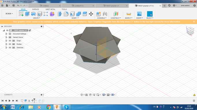
I used the miror option to get a similar one .i made some rotations then i combined the two bodies. Finally I applied a shell thikness about 5 mm .
You can download
fusion file
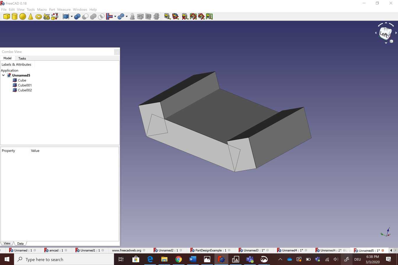
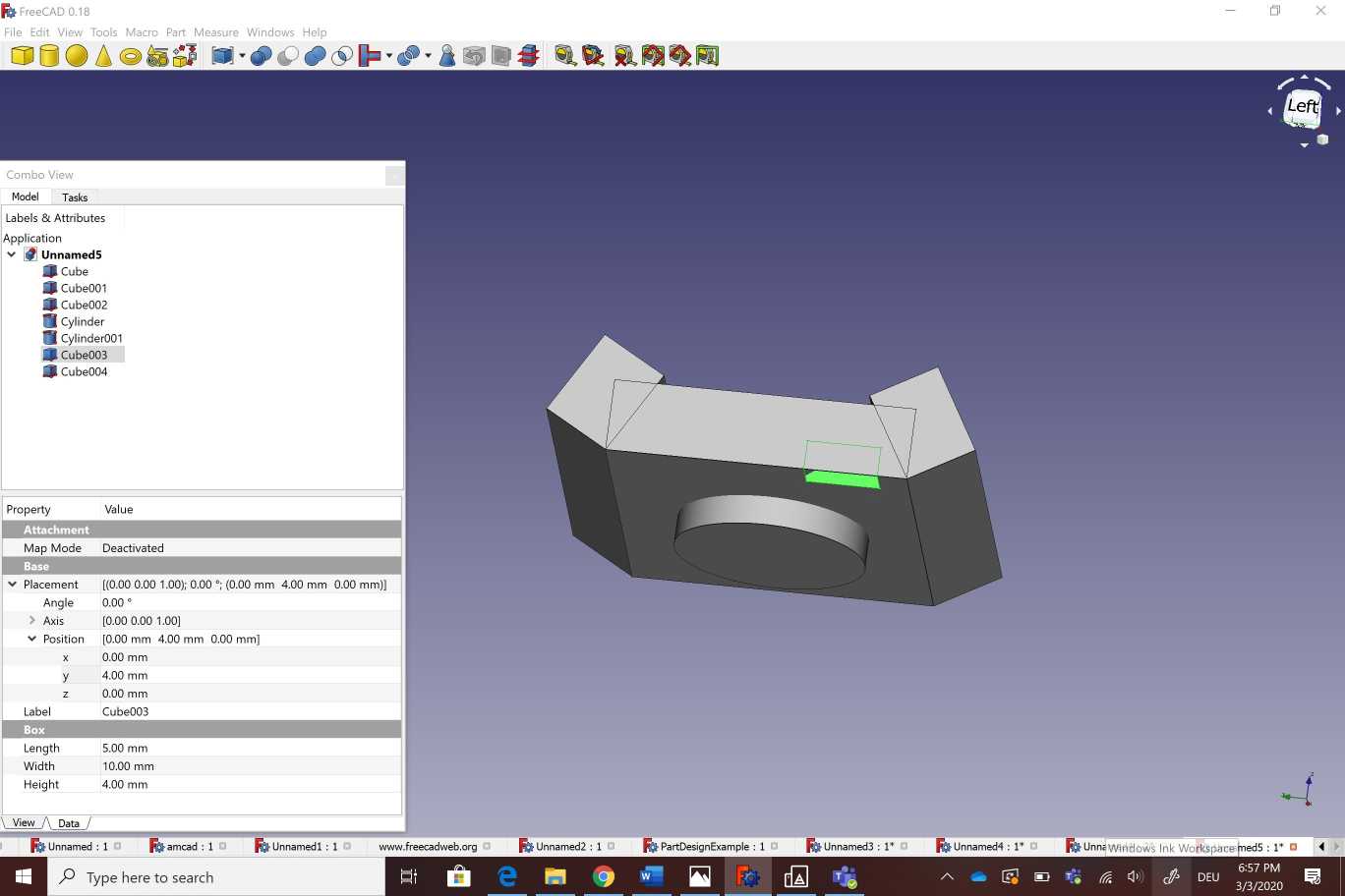
2.Free cad
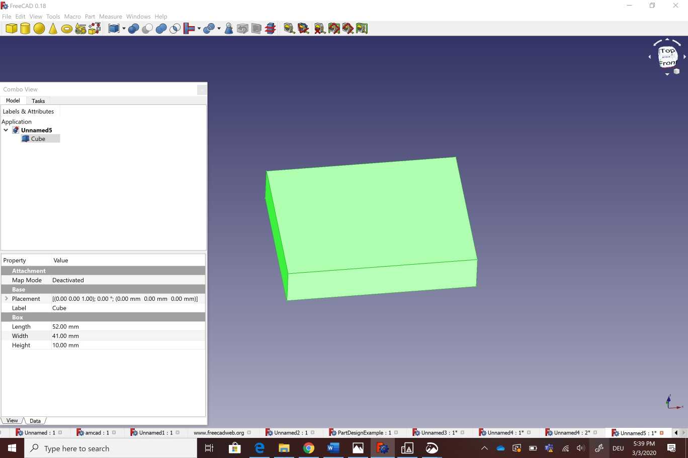
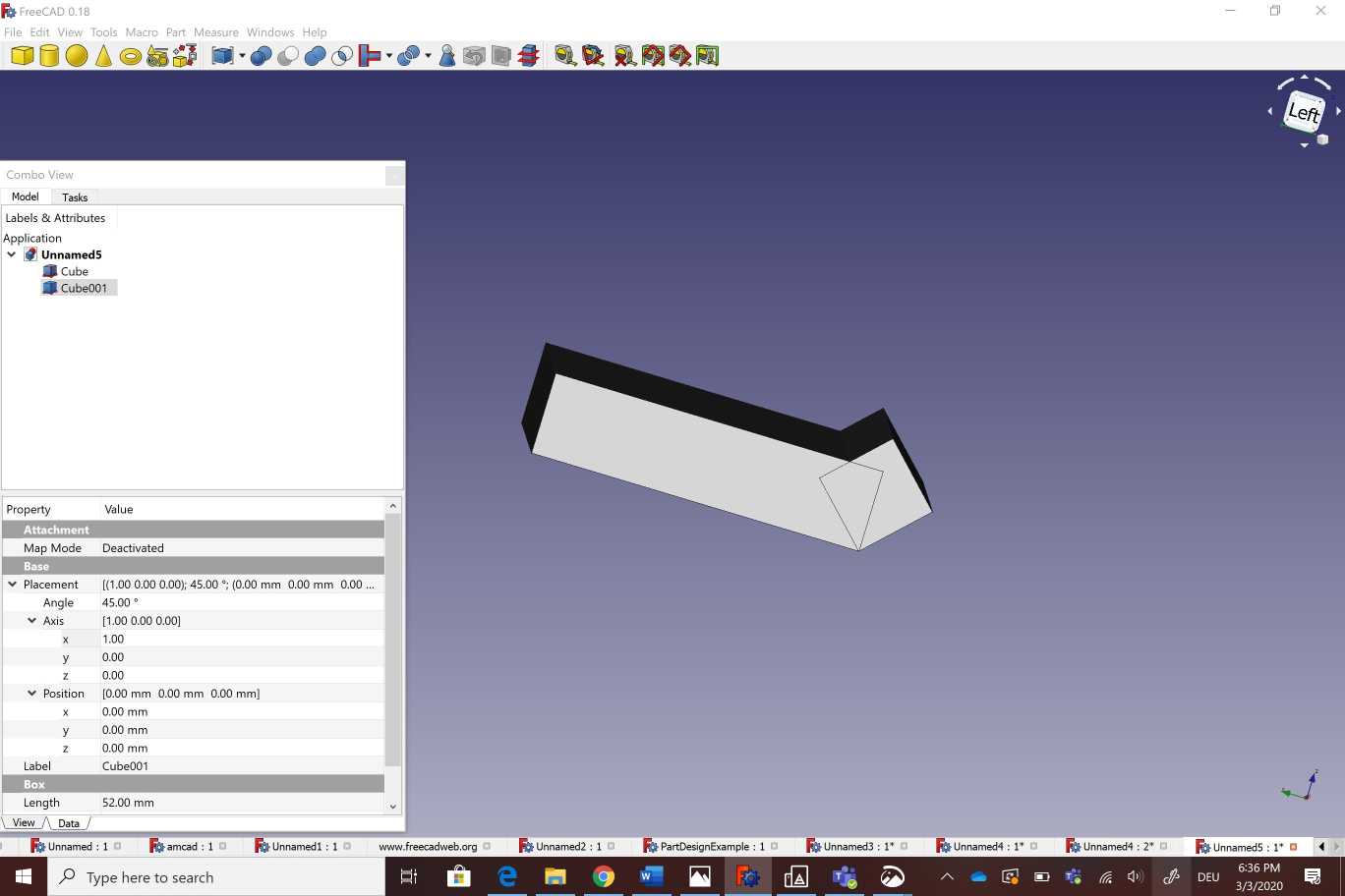
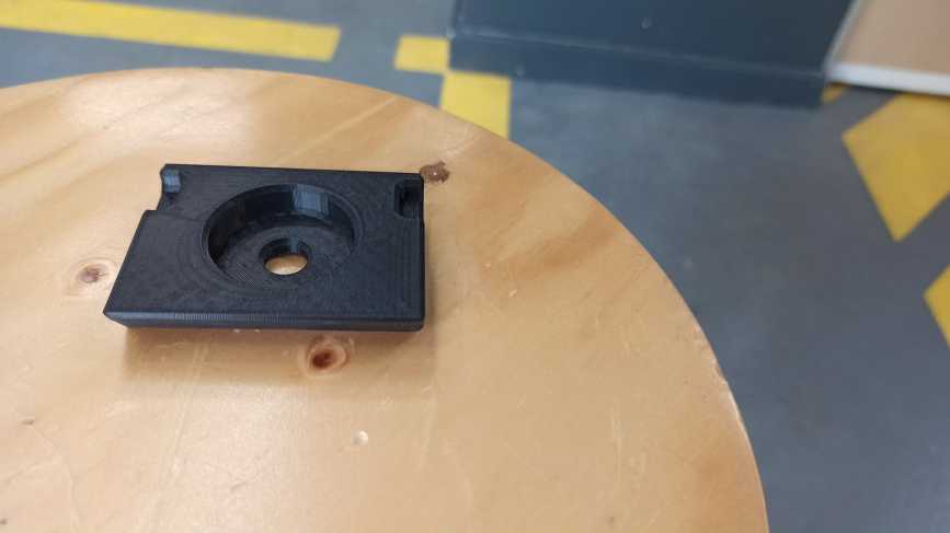
I used free cad to design a camera holder as showing bellow . I started by creating a cube with adjustable measurements .After that i created another cube with different angle (60°)and measurements . I copied the new cube on the other side of the part.The next step was about creating a hole b ading a cylinder Then i created two new cubes in the two sides of the part .Finally i selected all of those parts wich i want to substract from the main body . To make the printing process more easier and the part looks more pleasent to the eye I selected all theedges and i used the fillet option on the corners .
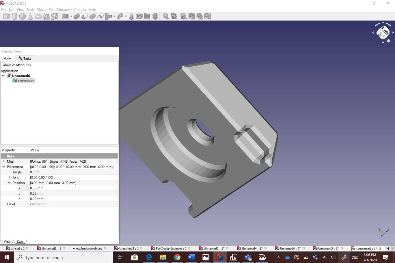
Here You can download freecad file
After designing the parts on fusion 360 and free cad,I imported the stl files on Idea maker .
Here you can find the stl file
Here you can download the stl file
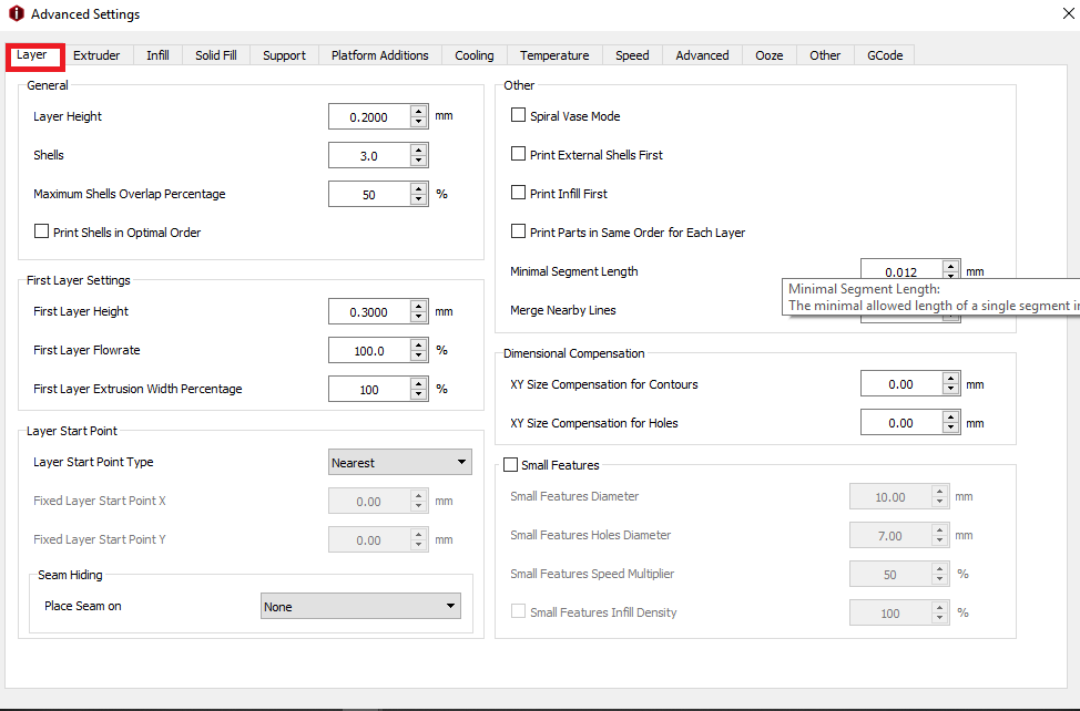
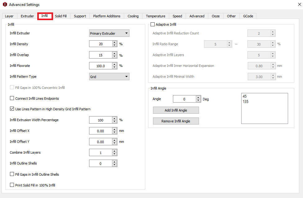
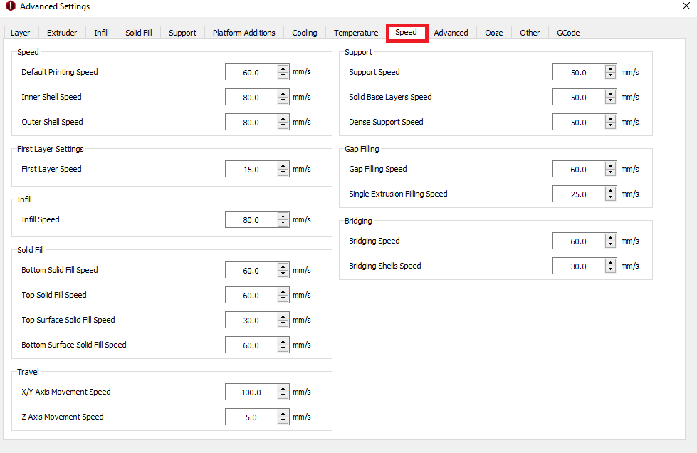
I used the same slicing parametres for the two objects
Raise 3d n1
Layer height: 0.2mm
Shels: 3
Infill: 20%
Speed: 60mm/s
Nozzle temp.: 205
Bed temp: 60
Material: PLA
These are the ojects wich i obtained after a 3d printing
# 3D Scanning
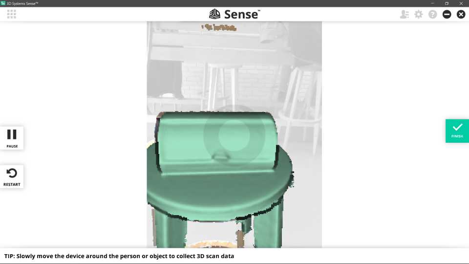
As the second part of the individual assignment ,I had to deal with the 3d scanning . In our Fab Lab we have 3d sense scanner.It uses lasers to sense the distance to the scanned objects. Using already scanned points and a flat reference surface, it is able to derive its own position and orientation relative to the scanned object. In addition , the scanner features a camera that is used to generate textures for the scanned object.
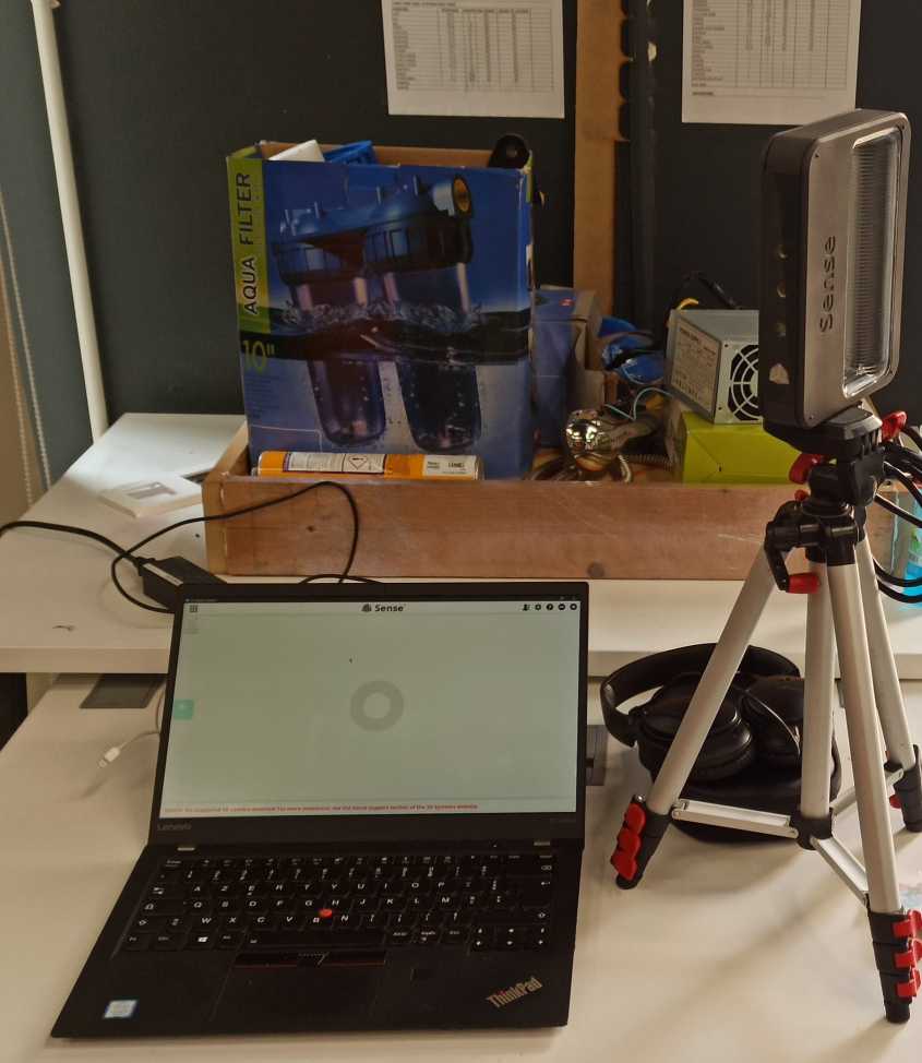
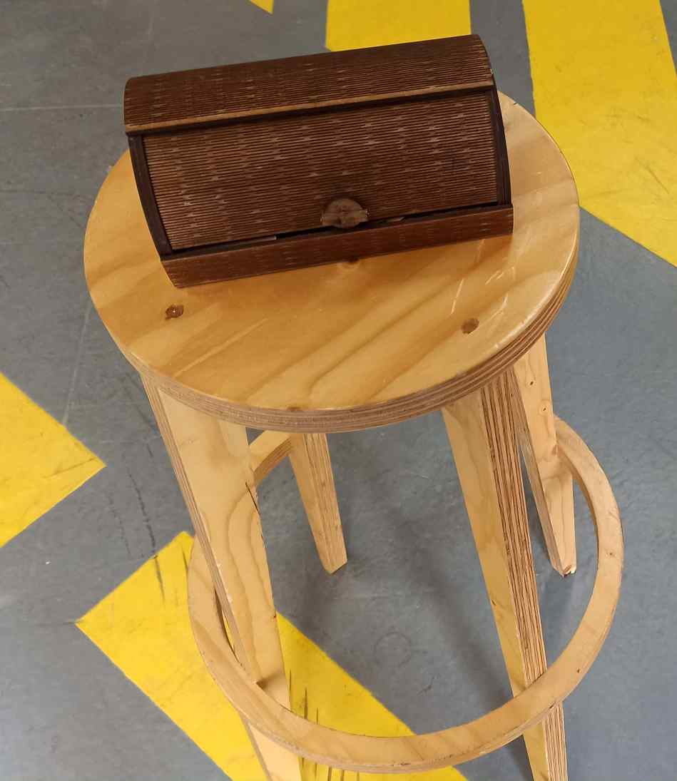
While scanning, one has to slowly move the scanner around the target object.The accompanying software 3d sense software shows what the scanner “sees” and whether the distance to the object is ok or not. It also notifies the user if the scanner looses track of the object because one moved to fast or below the reference surface. I scanned a jewelry box made in our fab lab
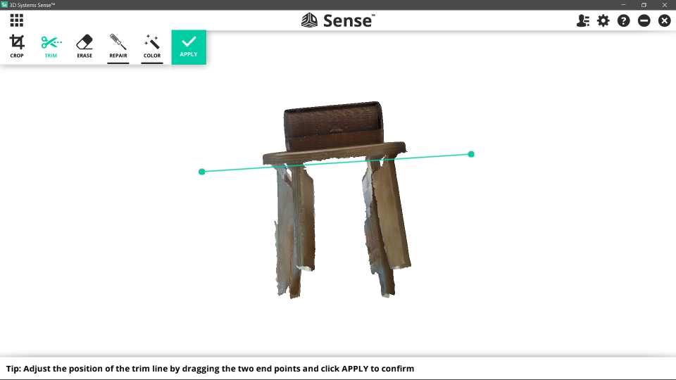
the software displays information on the size of the scan, whether the distance to the object is too large or too small, and what is currently seen by the scanner. After the scan, there are options to optimize the resulting mesh, for example, by removing unnecessary triangles, merging vertices, or adapting the base line of the scan. In my case i had to cut some extra parts as showin bellow
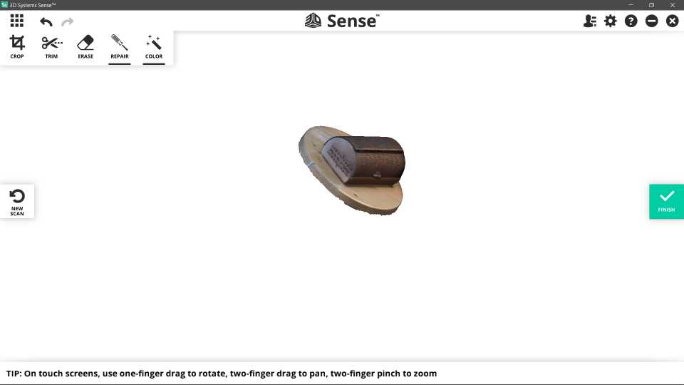
Finally, the scan can be exported as an .obj file.