4. Computer controlled cutting
A new adventure has started and I had to learn new techniques and softwares. I worked alongside my group to characterize our laser cutter, and test part(s)that vary cutting settings and dimensions. Individually, I designed a 2D model identifying the process involved in producing it by the laser cuttter
Laser cutting
Laser Cutting is a non-contact process which utilizes a laser to cut materials, resulting in high quality, dimensionally accurate cuts. The process works by directing the laser beam through a nozzle to the workpiece. A combination of heat and pressure creates the cutting action. The material melts, burns, vaporizes, or is blown away by a jet of gas, leaving an edge with a high-quality surface finish. The aim is to learn how to operate the machine and how to transform a 2D model into a real design Another group assignment was to identify the machine kerf to assure a better result of the cutting process
Group assignment
This direct link is for our group assignment
Here you can find what we have done sofar
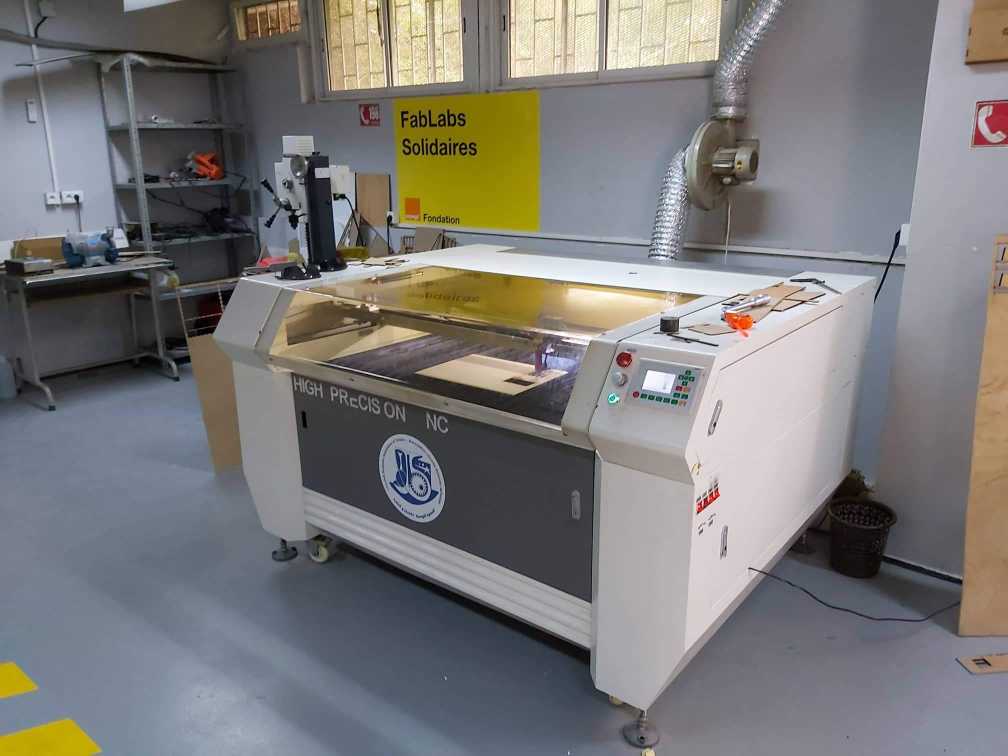
First we identified the laser cutter parametres
- Tool: Laser cutter CO2
-
Class: 3R (for this class, lasers are considered safe when handled carefully. There is only a small hazard potential for accidental exposure. For visible-light lasers, Class 3R lasers’ output power is between 1 and 4.99 milliwatts.
-
Laser Power: 100 watt.
-
Model: Golden Sign GS9070
-For the materials we used a Plywood/Mdf 4mm; Cardboard 6mm; Plexigrass 5mm
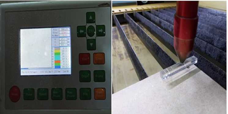
-For the setup of the machine we folowed these steps :
-
Decide what material you want to cut or engrave.
-
Choose an image to cut or engrave onto your chosen material
-
Upload the image into software that is compatible with your laser cutter
-
Set the dimensions of your image to match the size of your material
-
Place the material in the centre of the laser cutting mat
-
Set the lens height
-
Switch ON the laser
-
Switch ON the pointer
-
Unlock X/Y motor axes
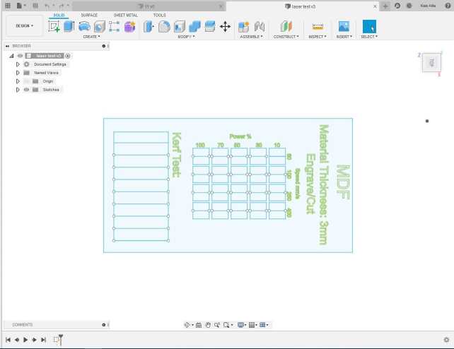
After charactirizing the machine ,we decided to made our own test template laser , we choose to test cutting and engraving at the same time on MDF 3mm with diffrent speed and laser power for each rectangle test . To design the 2D template on Fusion 360 we have drawn 9 rectangular pieces (10mm each) for 10 vertical cuts.
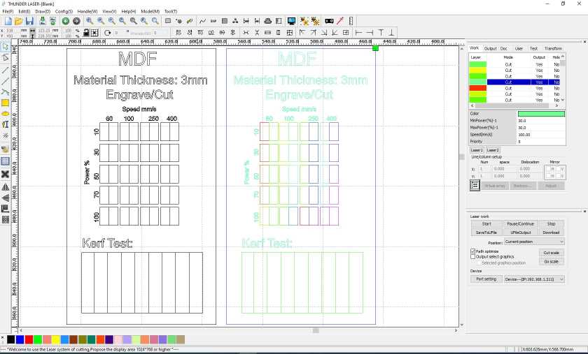
After the designing step we used RDworks or LaserCAD to manage the cutting plan . The software can set parameters (setting) like power, speed and frequency per color or for the whole job, but only lines thinner than dpi-dependent threshold are recognized to be cut. Since our template required so many different settings, we had to use multiple colored layers to stack all the power settings. RDworks has a limited number of layers and so it became very time consuming to cut even one template.
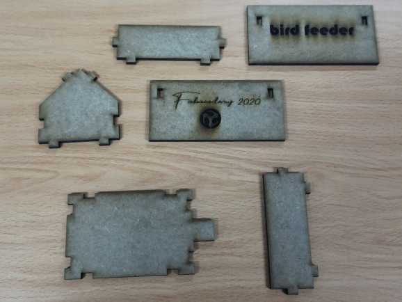
Here it is the final result
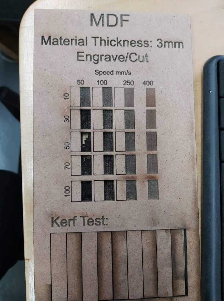
kerf test
“Be precise. A lack of precision is dangerous when the margin of error is small. Donald Rumsfeld.”
To begin characterizing the laser cutter it is first important to understand what the Kerf is. Kerf is defined as the width of material that is removed by a cutting process. is determined by material properties and thickness, the focal length of the lens and the gas used while cutting . to identify the kurf we have designed a simple test .We have drawn 9 rectangular pieces (10mm each) for 10 vertical cuts. This for make an average on the long distance
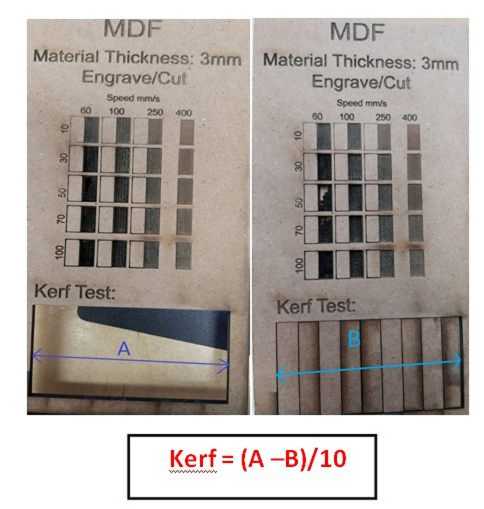
Finally we obtained 0.3mm as kerf . I will take it into consideration to design properly my model for the individual assignment as showing bellow:
Individual assignment
Parametric Cutout Construction Kit
Parametric is a term used to describe a dimension’s ability to change the shape of model geometry as soon as the dimension value is modified .
Fusion 360
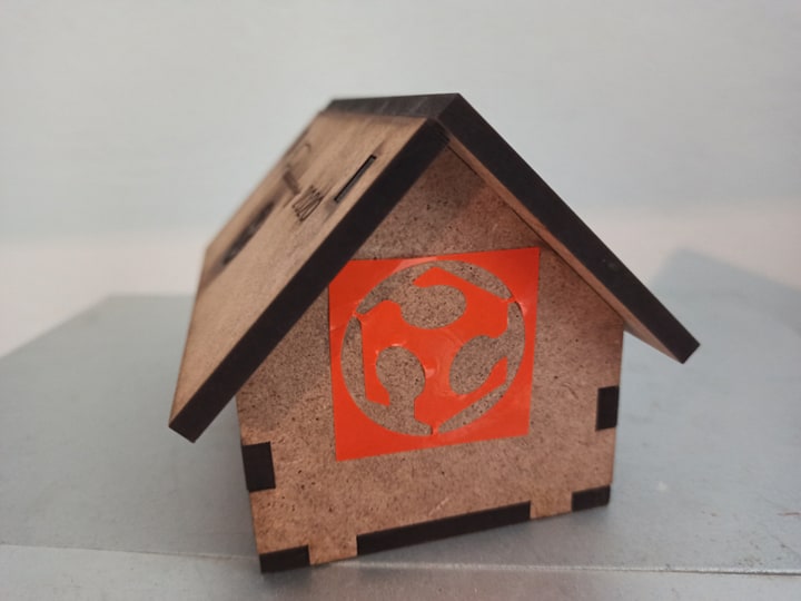
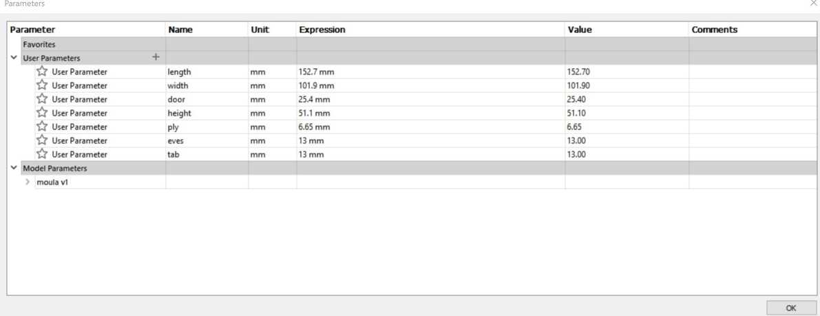
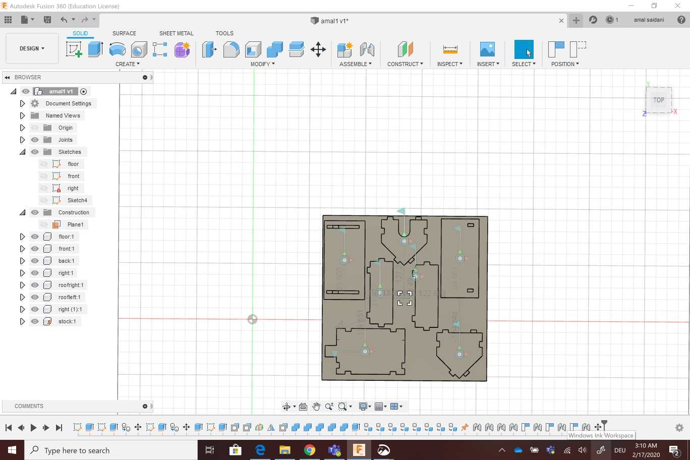
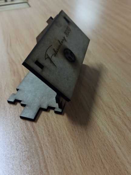
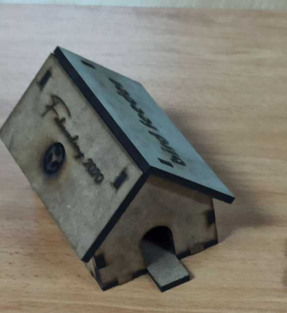
The first idea that comes to my mind is to build a bird house . the first step was to adjust my design parametres on fusion 360
I started by designing the floor . I added a new sketch on (xy plan )and i created a 2 point rectangle with the same dimensions that i adjusted before ( width , length)
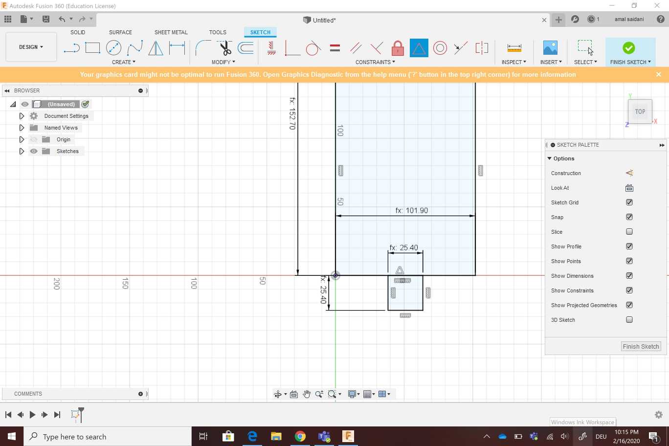
I Extruded the floor , i created a new sketch (rectangle) to add the front
I reused the front to create a back copie
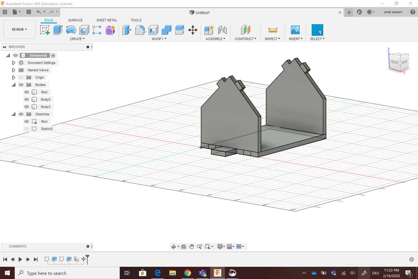
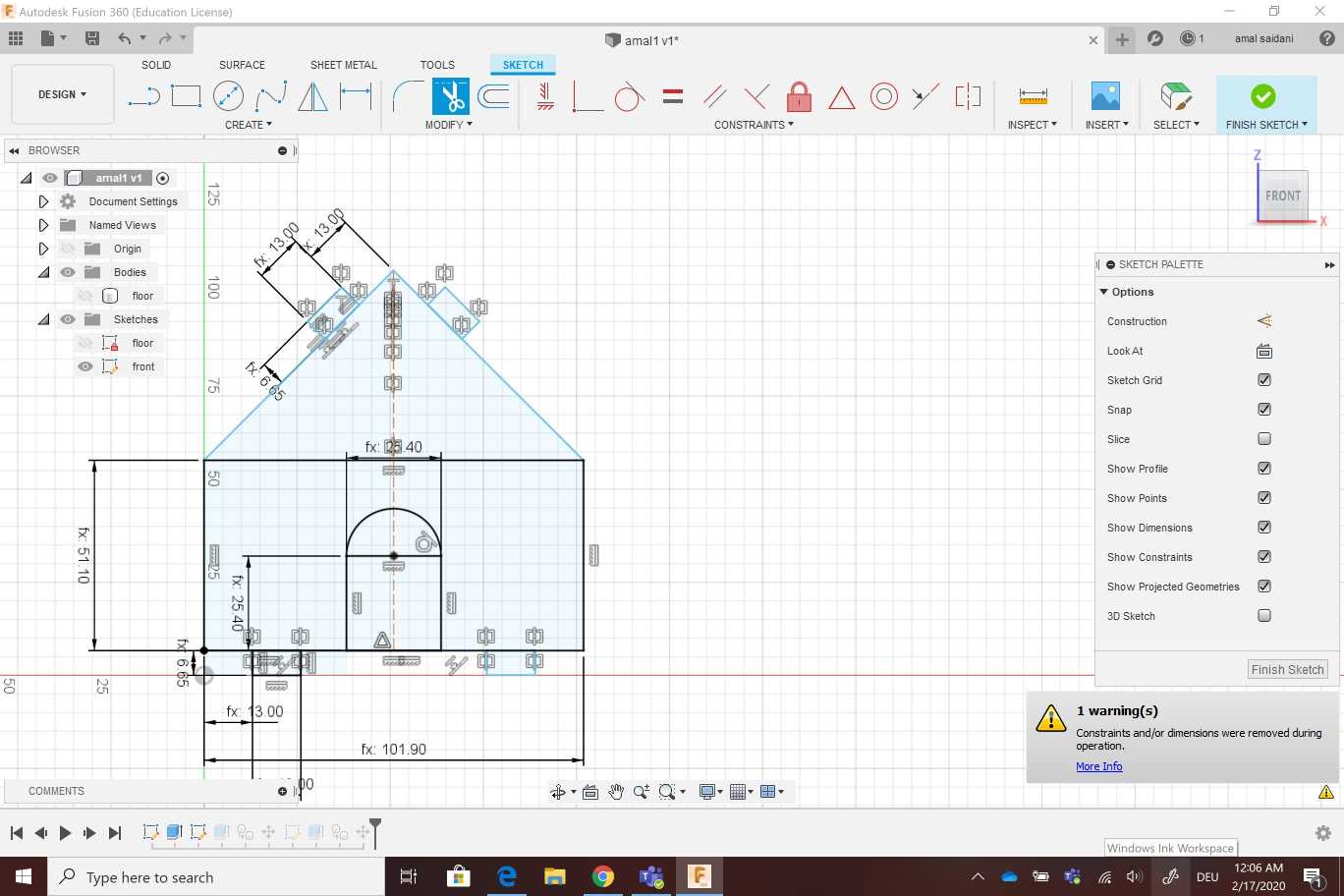
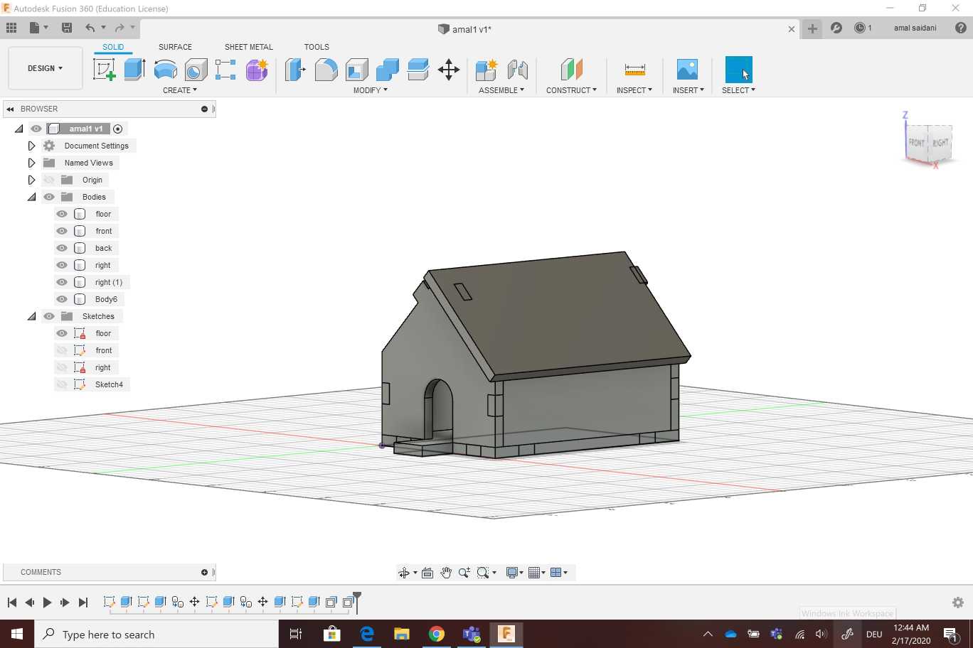
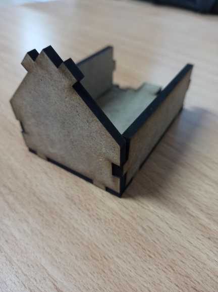
I created the right side then i did a copy for the left one . After that i designed the door on the front by edit sketch extrude and cut .For the roof i created just one side then iconstructed a plan to use the miror for the other side
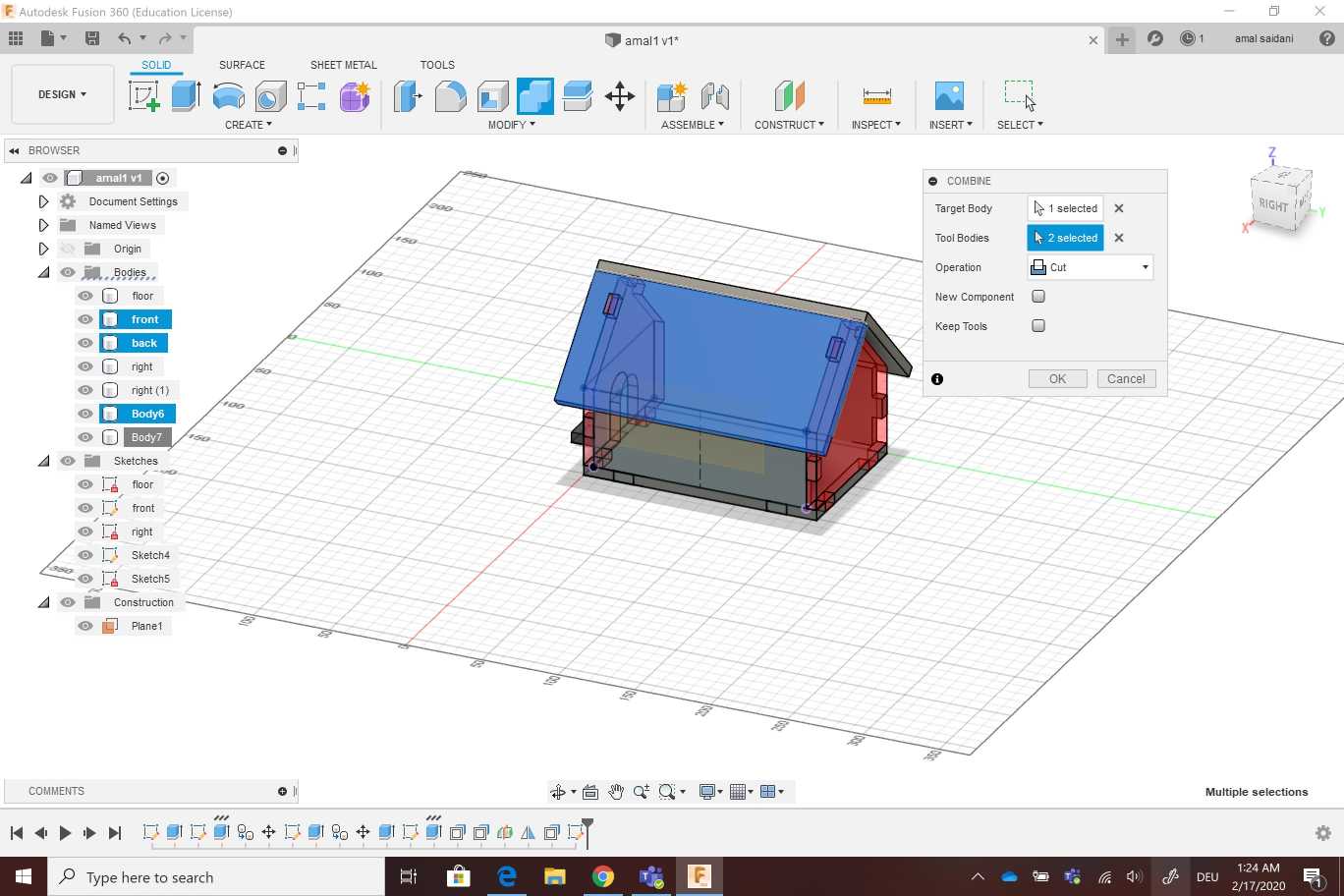
The next step was the cut so i had to select parts to cut and To mak sure that i did the cut well i checked interfences and i figured out that d any interfences was detected
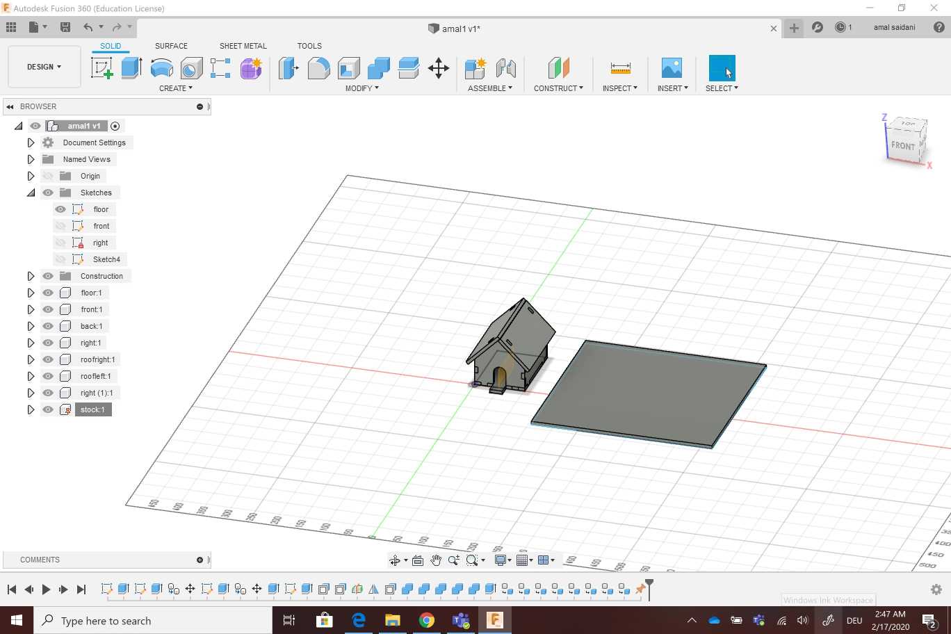
The final step was creating a piece of materiel to make all the parts lay on (ground), that’s why i reused the floor sketch .
I Turned all the bodies into components to use joins then i placed all the pieces on the ground .Finally i saved it as DXF file. i sent the file to the machine and i started working on a 6mm MDF
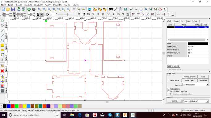
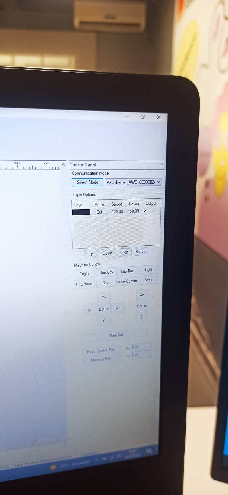
To adjust the machine , i used the following parameters
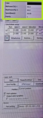
Min Power(%)-1: 90
Max Power(%)-1: 90
speed(mm/s):30
You can download files from here :
Second design
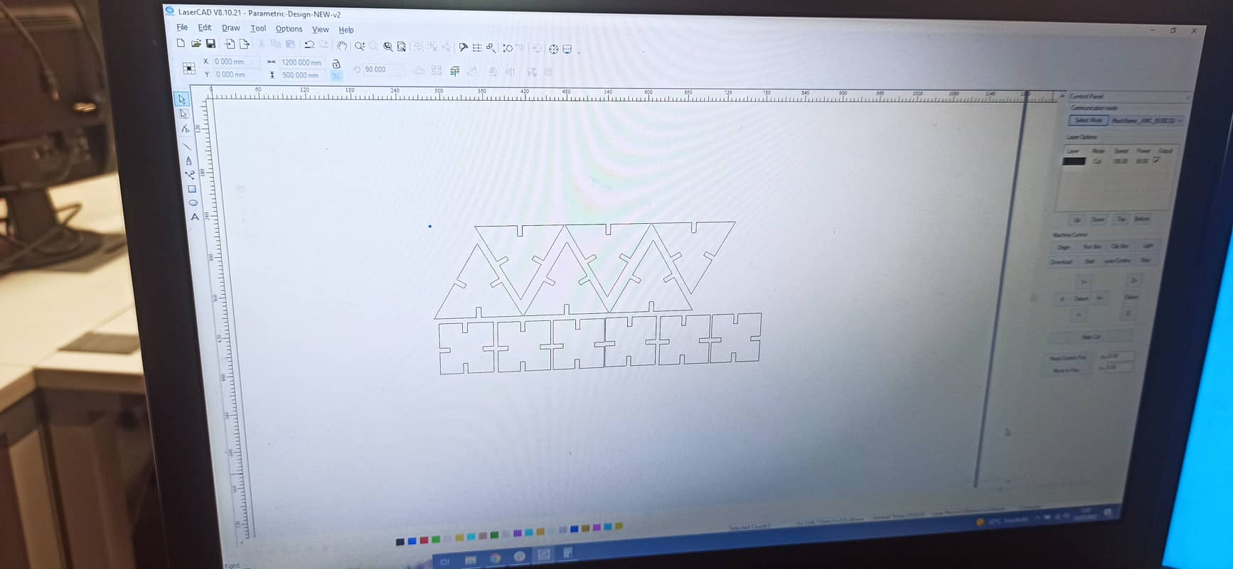
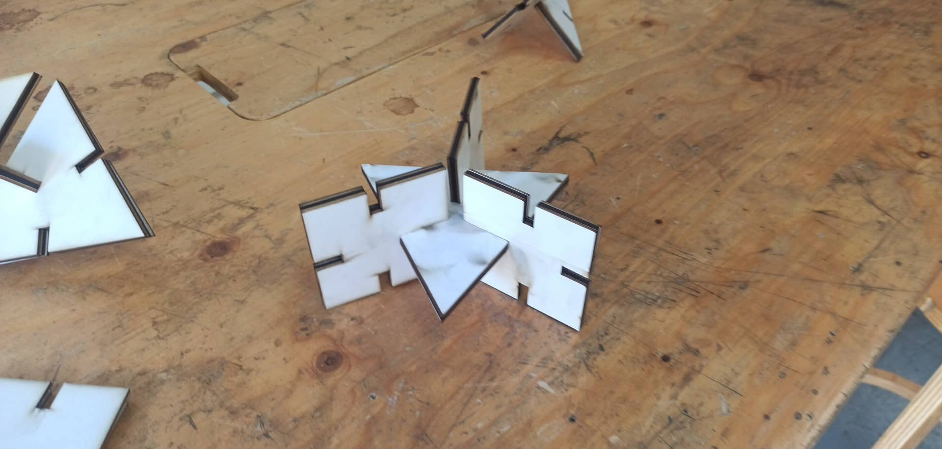
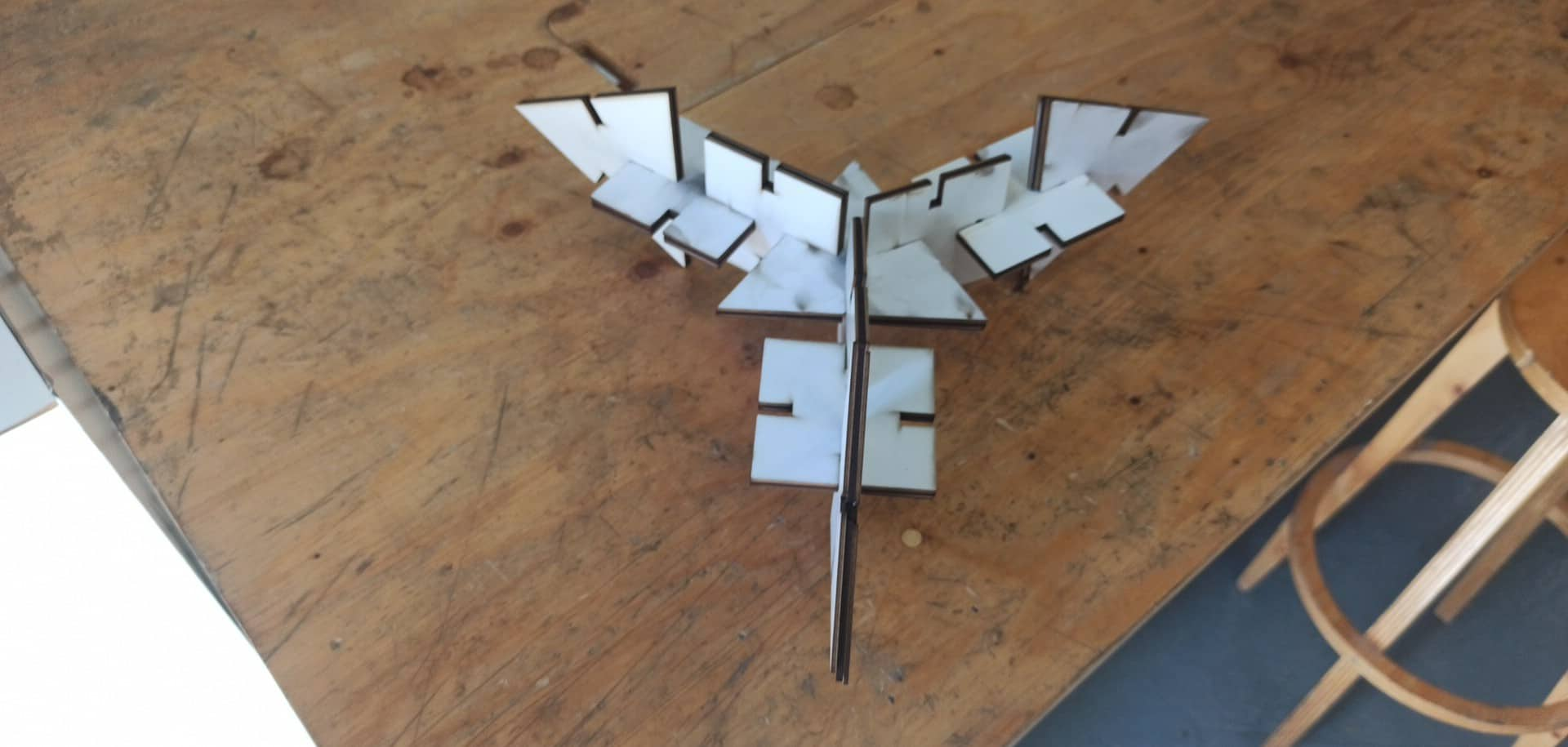
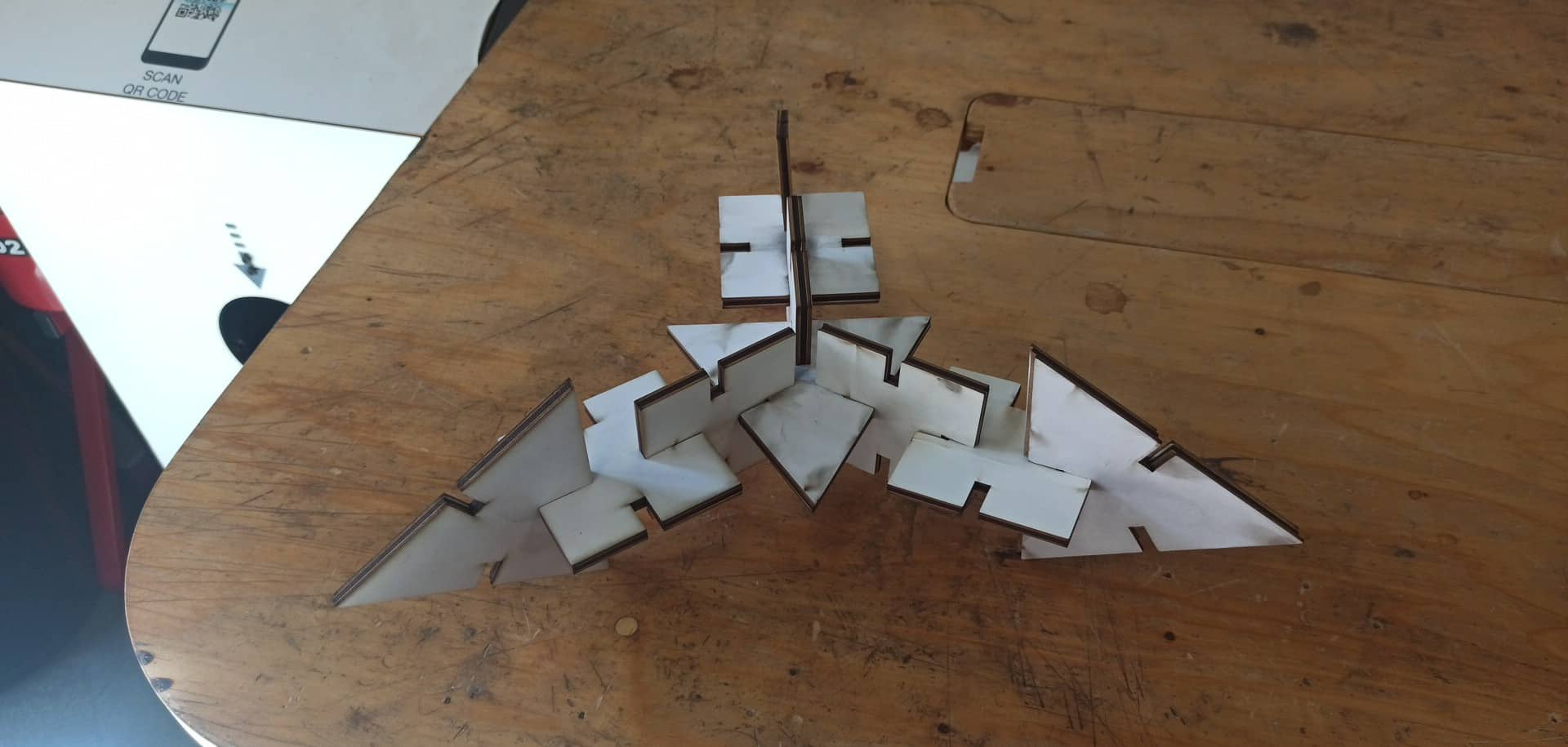
I wanted to create two different pieces, a square and a triangle that I could mix and match which can be assembled in multiple ways. I knew that I needed these parametric to design my construction kit
When designing in Fusion 360 I started by fixing all the parametres m gonna use
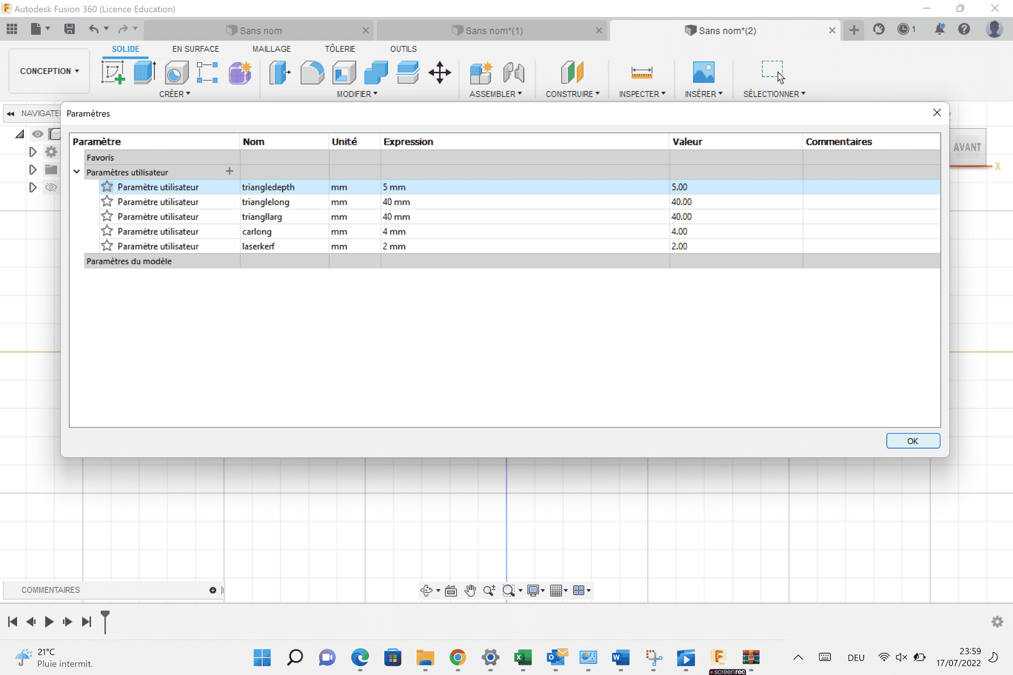 I followed these steps in Fusion to create the parametric piece
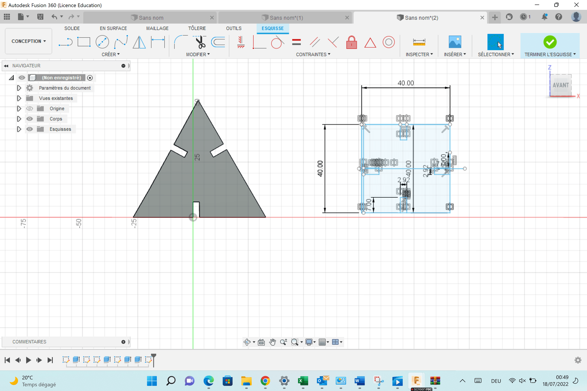
I created a square sketch that was 4cm x 4cm
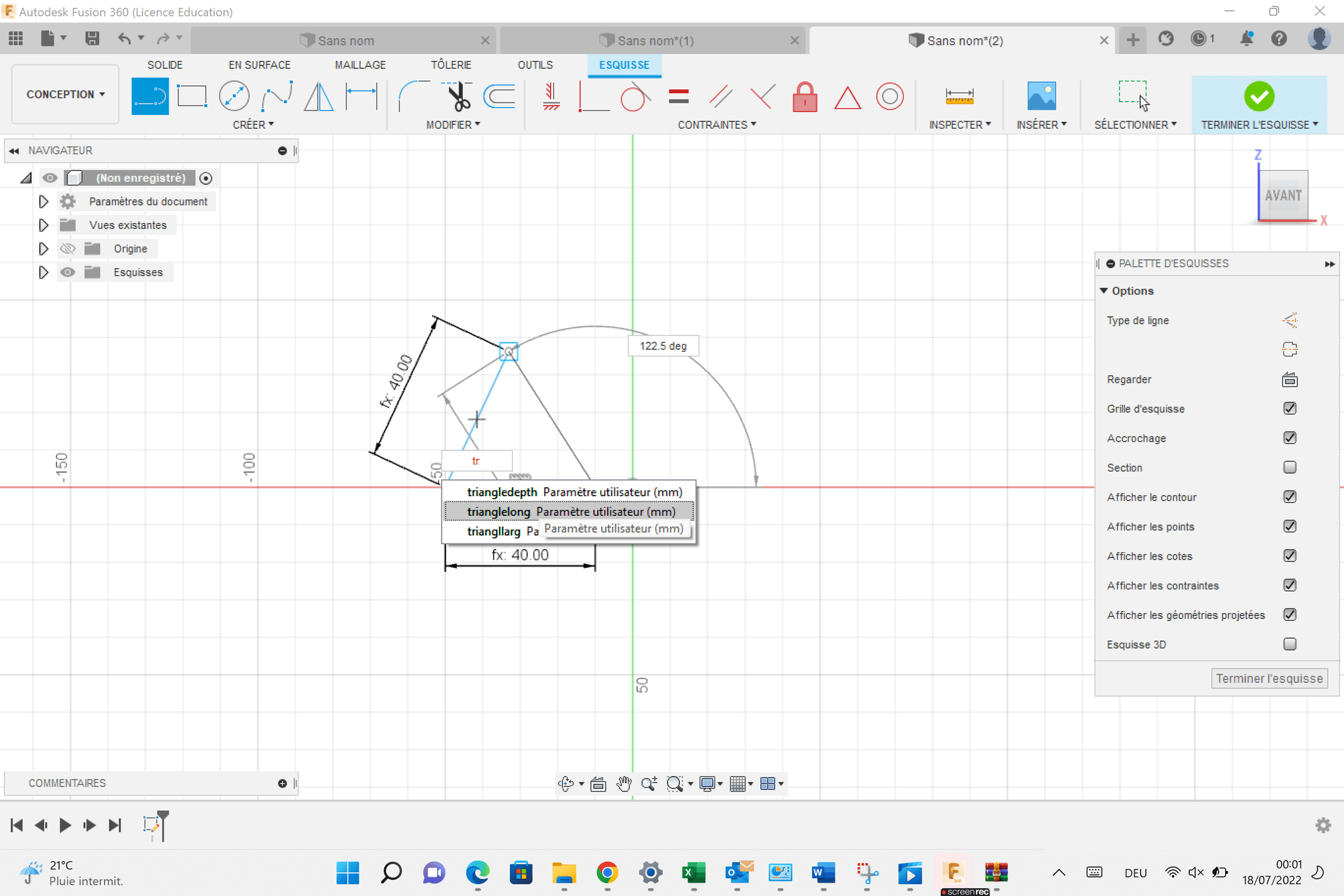
I created a small tab on the square using construction lines
Start from the center of one side of the square then create a construction line half of the distance of the material thickness from that point
Create another point that goes in the opposite direction
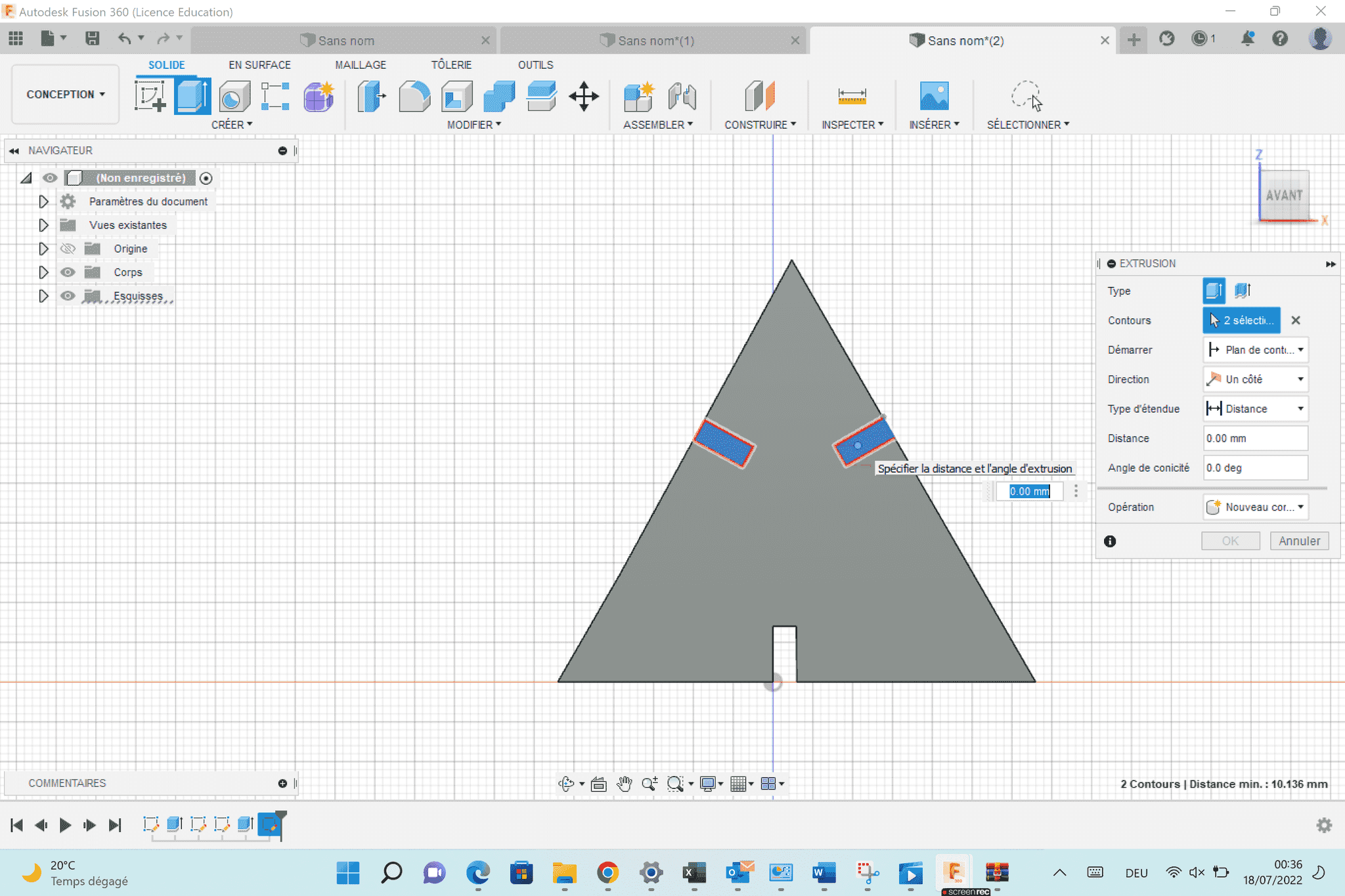
Use a 3-point triangle connecting the two endpoints on the construction line then the tab length I wanted
I followed these steps in Fusion to create the parametric piece
I created a square sketch that was 4cm x 4cm
I created a small tab on the square using construction lines
Start from the center of one side of the square then create a construction line half of the distance of the material thickness from that point
Create another point that goes in the opposite direction
Use a 3-point triangle connecting the two endpoints on the construction line then the tab length I wanted
Uploading and Operating Laser Cutter
I downloaded this file as a . DXF
To adjust the machine , i used the following parameters
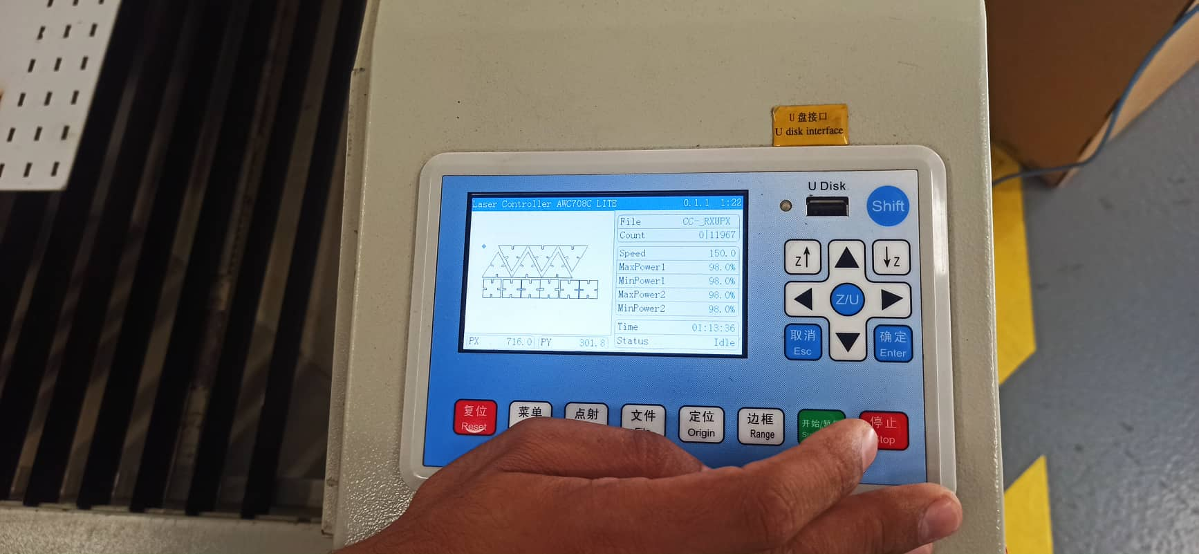
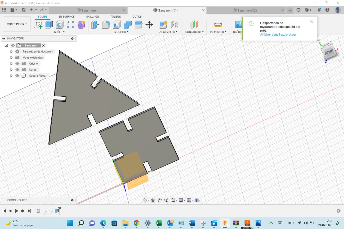
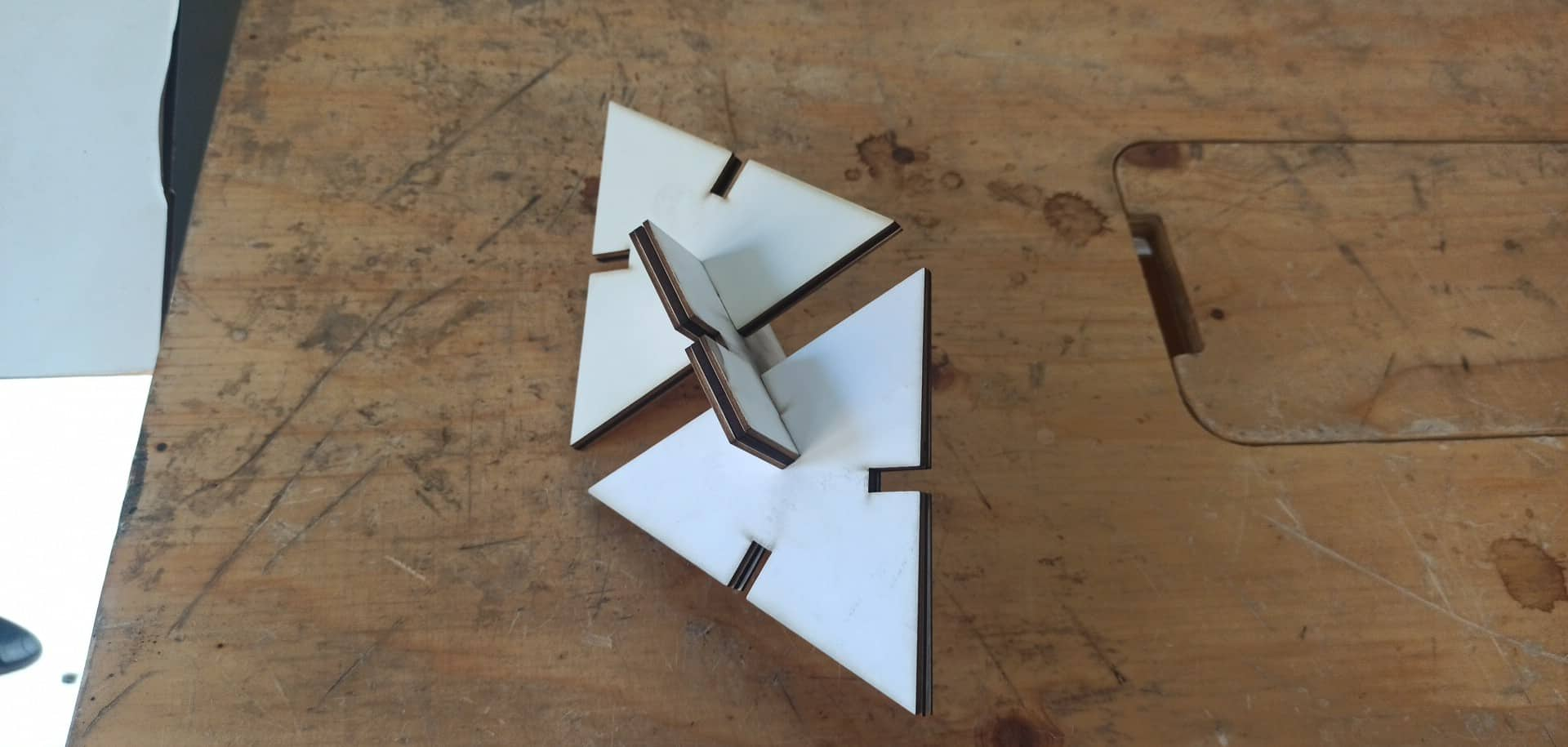
I got a good result ,my two pieces mach perfectly and it could assembled in multiple ways as showing bellow
 here you can download files here
vinyl cutting
For the vinyl cutting assignment I started by downloading these png models


Source

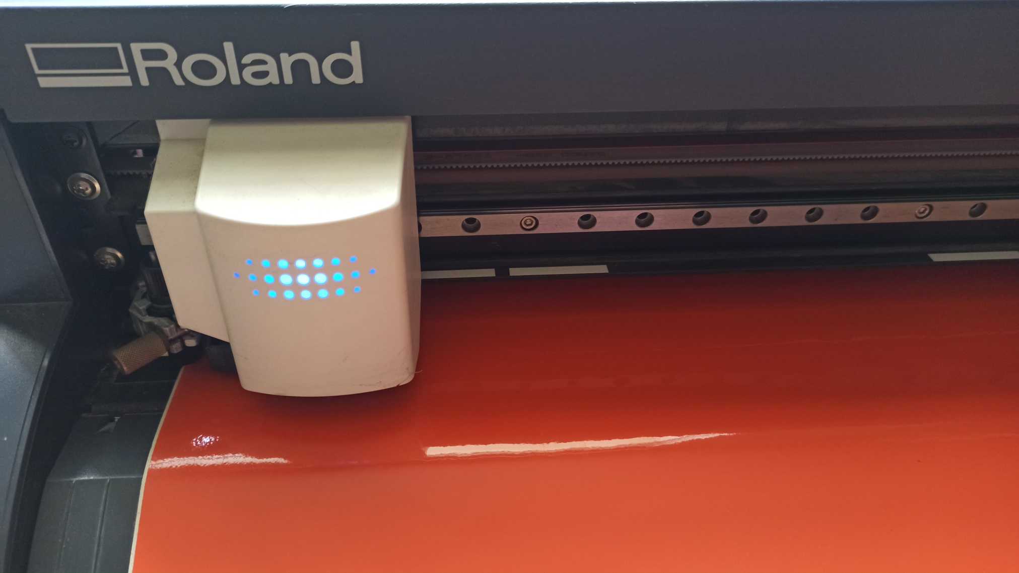
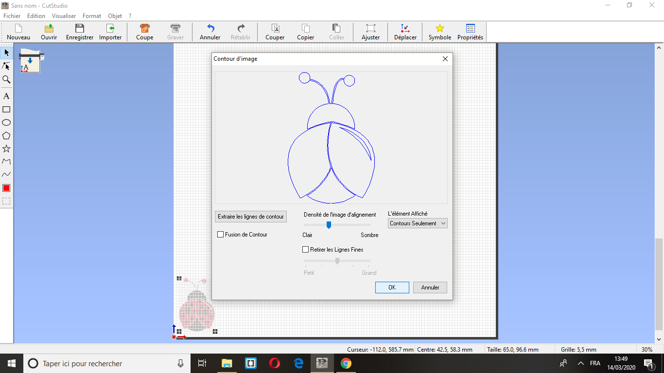
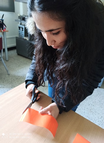
I used Roland GX-24 for the vinyl cutting. I imported my png files into the CutStudio SW then i introduced from the front a piece of orange matte vinyl, and after pulling a pedal on the backside of the machine, the roller parts that fix the vinyl to the mechanism, we adjust the piece of vinyl to be parallel to the cutting line, and pulling back the pedal ensure it is well trapped. the machine automatically checks the dimensions of the piece.
For placing the vinyl it’s very useful to work with some twizzers to hold and pick the smallest pieces, and painters tape to transfer the pieces from the vinyl to the final placement.
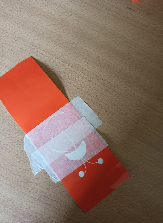
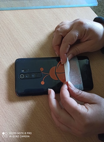
While placing the vinyl It’s important to press and scratch over the painters tape to make the vinyl stick onto the surface firmly. Then, remove carefully the tape
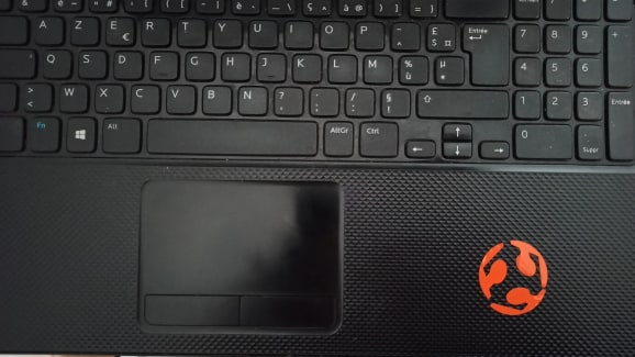
Here are my amazing stickeres