10. Input Devices
This week is about understanding input devices and using them in a circuit to measure something.
Group Assignment:
- Measure the analog levels and digital signals in an input device.
Individual Assignment:
- Measure something: add a sensor to a microcontroller board that you have designed and read it.
Group assignment
Check this link to check what we had done to measure the analog levels and digital
signals in an input device
Individual assignment
An input device
is a piece of computer hardware equipment used to provide data and control signals to an information processing system such as a computer or information appliance.”
In Fab Acadmemy, mostly We use Sensors as Input Devices.
A sensor
is a device that detects and responds to some type of input from the physical environment. The specific input could be light, heat, motion, moisture, pressure, or any one of a great number of other environmental phenomena. The output is generally a signal that is converted to human-readable display at the sensor location or transmitted electronically over a network for reading or further processing.
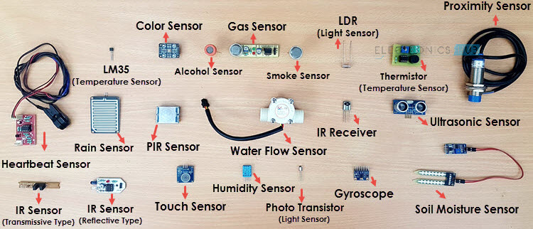
Here are a few examples of the many different types of sensors:
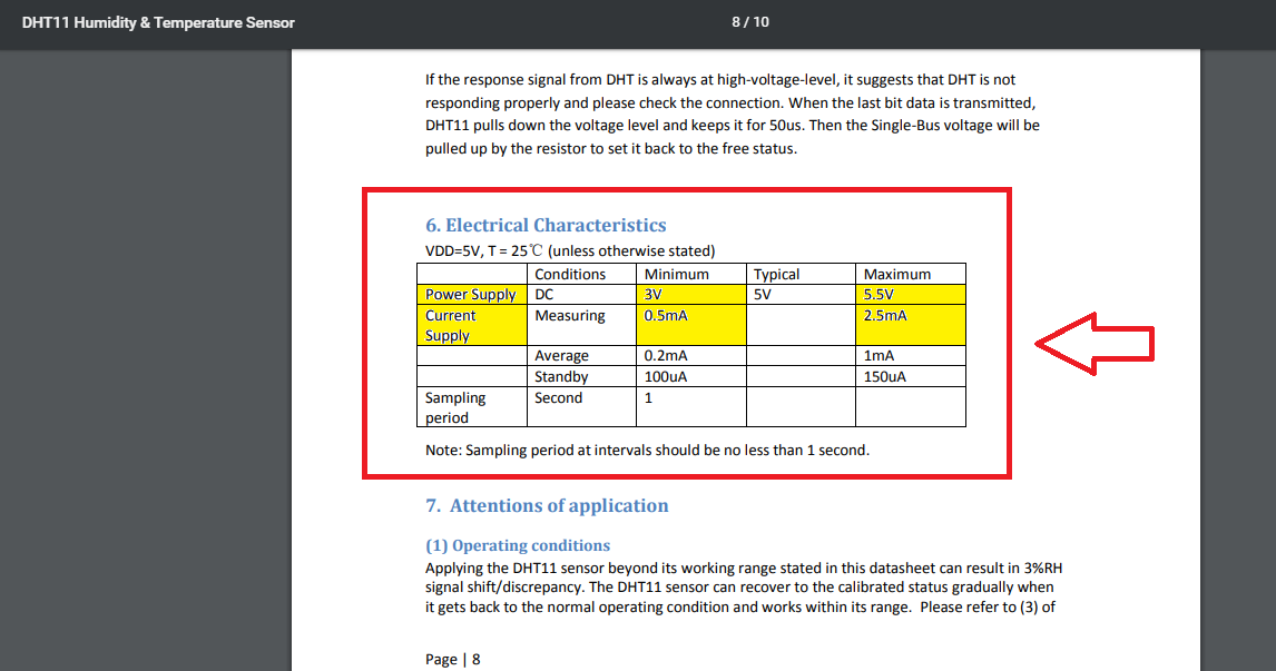
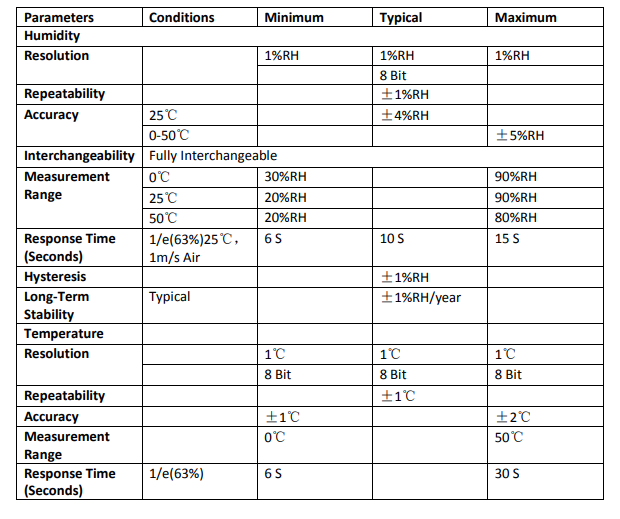
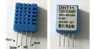
For my individual assignment i decided to add a DHT11 sensor .It allows to measure Temperature and humidity needed for my final project .I started to read the datasheet of this sensor in order to understand and learn a bit about the physical inetrfacing size and digital output
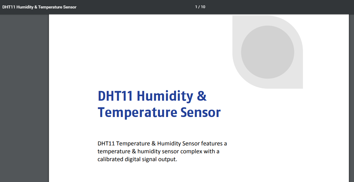
DHT11 Temperature & Humidity Sensor features a temperature & humidity sensor complex with a calibrated digital signal output. By using the exclusive digital-signal-acquisition technique and temperature & humidity sensing technology, it ensures high reliability and excellent long-term stability. This sensor includes a resistive-type humidity measurement component and an NTC temperature measurement component, and connects to a highperformance 8-bit microcontroller, offering excellent quality, fast response, anti-interference ability and cost-effectiveness
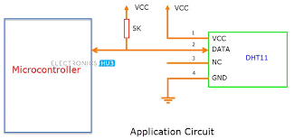
Typical application
After datasheet learning and information collecting , It’s time to design my board adding the new sensor.I choose to use my Hello board from the week 7
Programming
First i had to add the sensor library to the arduino uno library
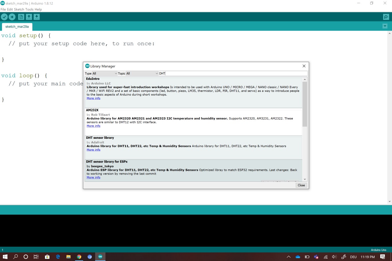
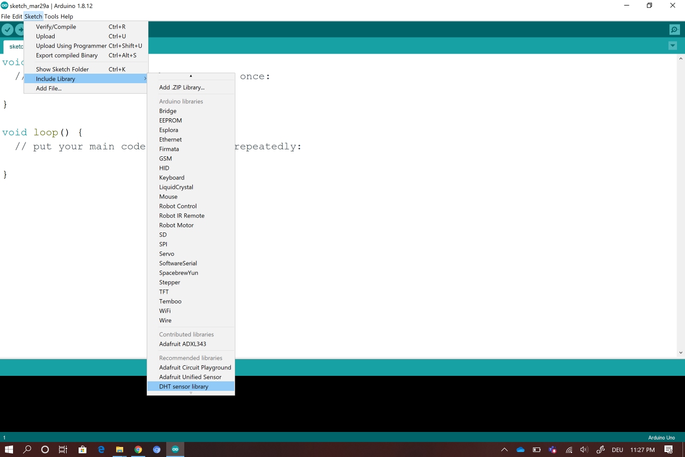
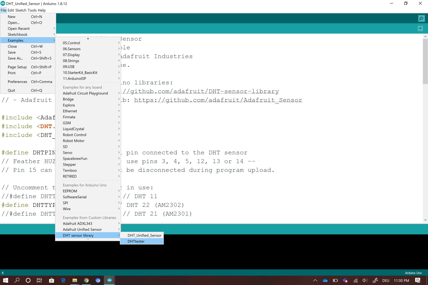
After downloading the DHT11 library i started reading my code to program the sensor
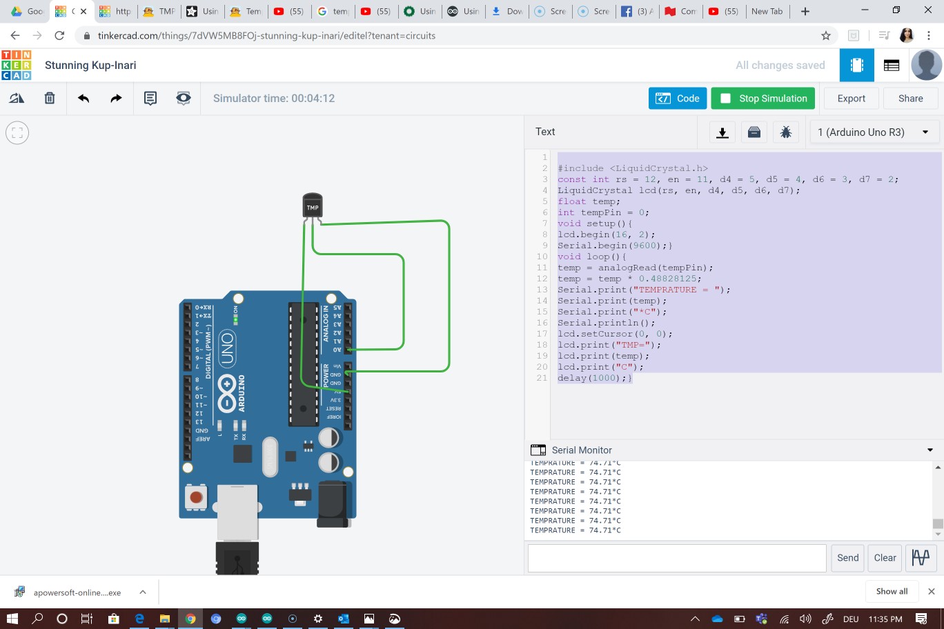
Unfortunately because of the covid19 i can’t acess the fab ab and i can’t bring the arduino so i thinked about a kind of simulation for the temperature sensor on the software tinkercad .So i just downloaded the code and istarted simulation
Fortunately after a while ,the covid 19 pandemic dereased a little bit which allow us to acess the fab lab .
Now i can try my code using the arduino. I conected the DHT11 to the arduino as following
to connect the DHt11 to arduino i had to follow these onnections
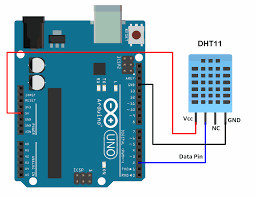
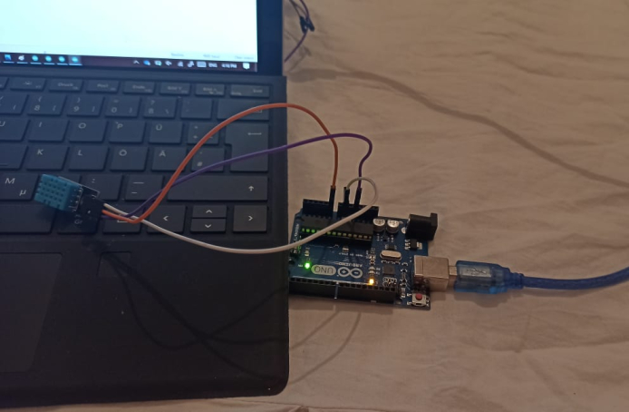
VCC to the 5V arduino
GND to GND arduno
The Data pin to the arduino pin A0
I started by writing my code
First i had to include my library #includedht.h
Then define in which pin i connected my DHT sensor #define dht_apin A0
In the void setup()
I defined a delay of 5 seconds so the system can boot
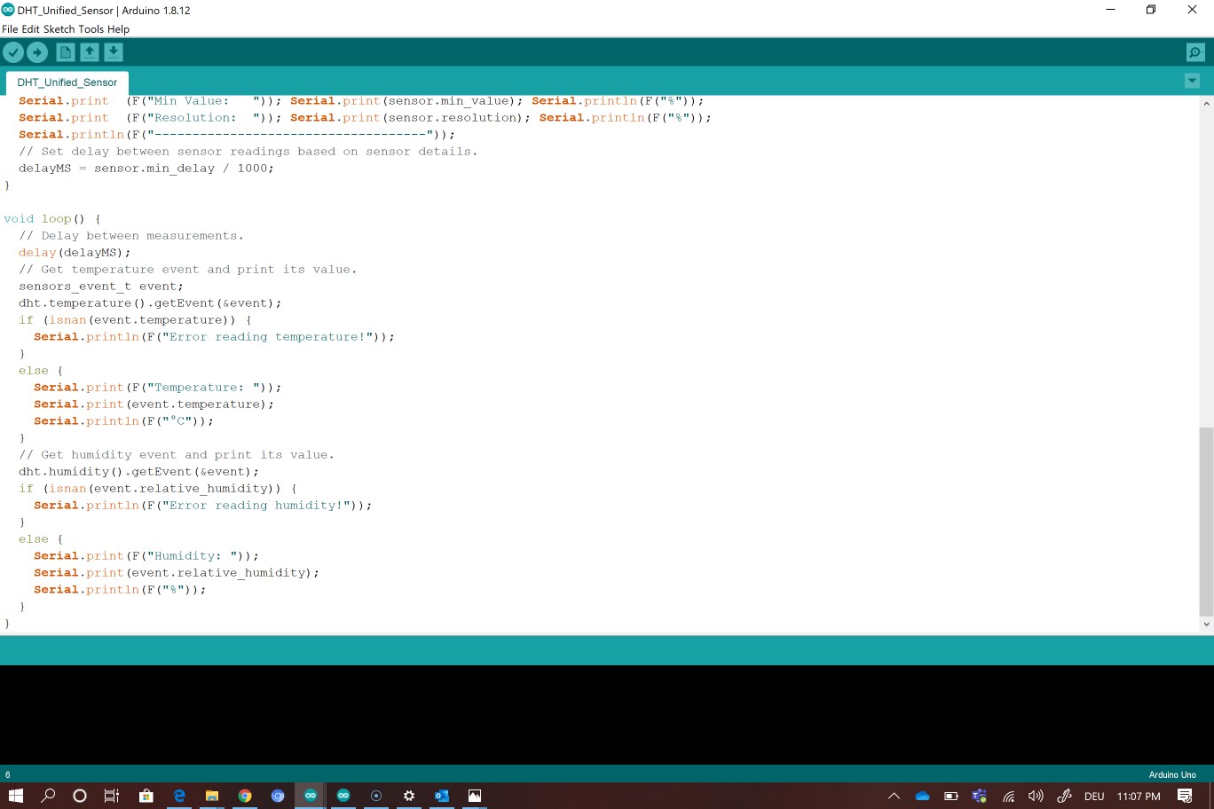
In the void loop()**
i writed the commands to recieve the DATA (Temperature and humidity from the sensor)
Here it is the code
#include <dht.h>


#define dht_apin A0 // Analog Pin sensor is connected to

dht DHT;

void setup(){

Serial.begin(9600);
delay(5000);//Delay to let system boot


 }//end "setup()"

void loop(){
//Start of Program

DHT.read11(dht_apin);

Serial.print("Current humidity = ");
Serial.print(DHT.humidity);
Serial.print("%  ");

Serial.print("temperature = ");
Serial.print(DHT.temperature);
Serial.println("C  ");
delay(500)
}
Check this video
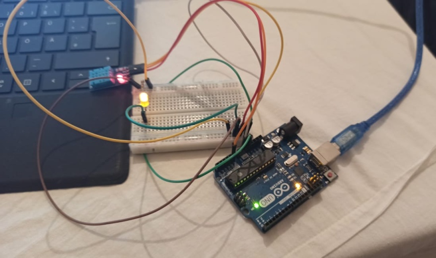
After my first try with DHT11 , i tried to add an LED and make it blinks at a certain value of temperature
I writed the following code to blink the LED when The temperature is bigger then 10° (T>10°) and to make it off if it is the opposite
I can see at the same time a response from the LED “m blinking”
if("temperature">=10){  // See if the temperature is bigger then 10C.

Serial.println("m blinking ");

digitalWrite(yellowLED, HIGH);  // The yellow led will turn on.

}
else if("temperature"<10){   // If the temperature is smaller than 10C.

digitalWrite(yellowLED, LOW);  // The yellow led will turn off.

}

}
Here you can find my code
#include <dht.h>


#define dht_apin A0 // Analog Pin sensor is connected to

dht DHT;

const int yellowLED = 9;  // Adds a led light (in that case, it is yellow) to pin 9.

void setup(){

Serial.begin(9600);

delay(5000);//Delay to let system boot


digitalWrite(yellowLED,LOW);  // Turn off LED.

}//end "setup()"

void loop(){

//Start of Program

DHT.read11(dht_apin);

Serial.print("Current humidity = ");

Serial.print(DHT.humidity);

Serial.print("%  ");

Serial.print("temperature = ");

Serial.print(DHT.temperature);

Serial.println("C  ");

delay(5000);//Wait 5 seconds before accessing sensor again.


if("temperature">=10){  // See if the temperature is bigger then 10C.

Serial.println("m blinking ");

digitalWrite(yellowLED, HIGH);  // The yellow led will turn on.

}
else if("temperature"<10){   // If the temperature is smaller than 22C.

digitalWrite(yellowLED, LOW);  // The yellow led will turn off.

}

}
Check the video
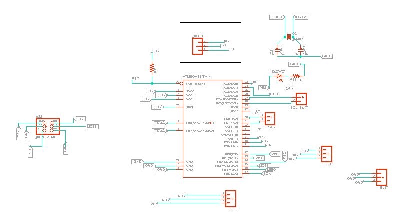
Making my own board
Now it i time to make my own board for the input week . I will test the DHT using this board so in Eagle i made the schematic and i used the atmega328p microcontroller . At first i was thinking of using an attiny 44 microcontroller but as smd i only found the atmega328p available in my country . I connected the DHT 11 using three pins the VCC the GND and the Data pin which is connected to the analog pin A0 of the microcontroller .The other components are almost the same components i used to make my hello board in week 7
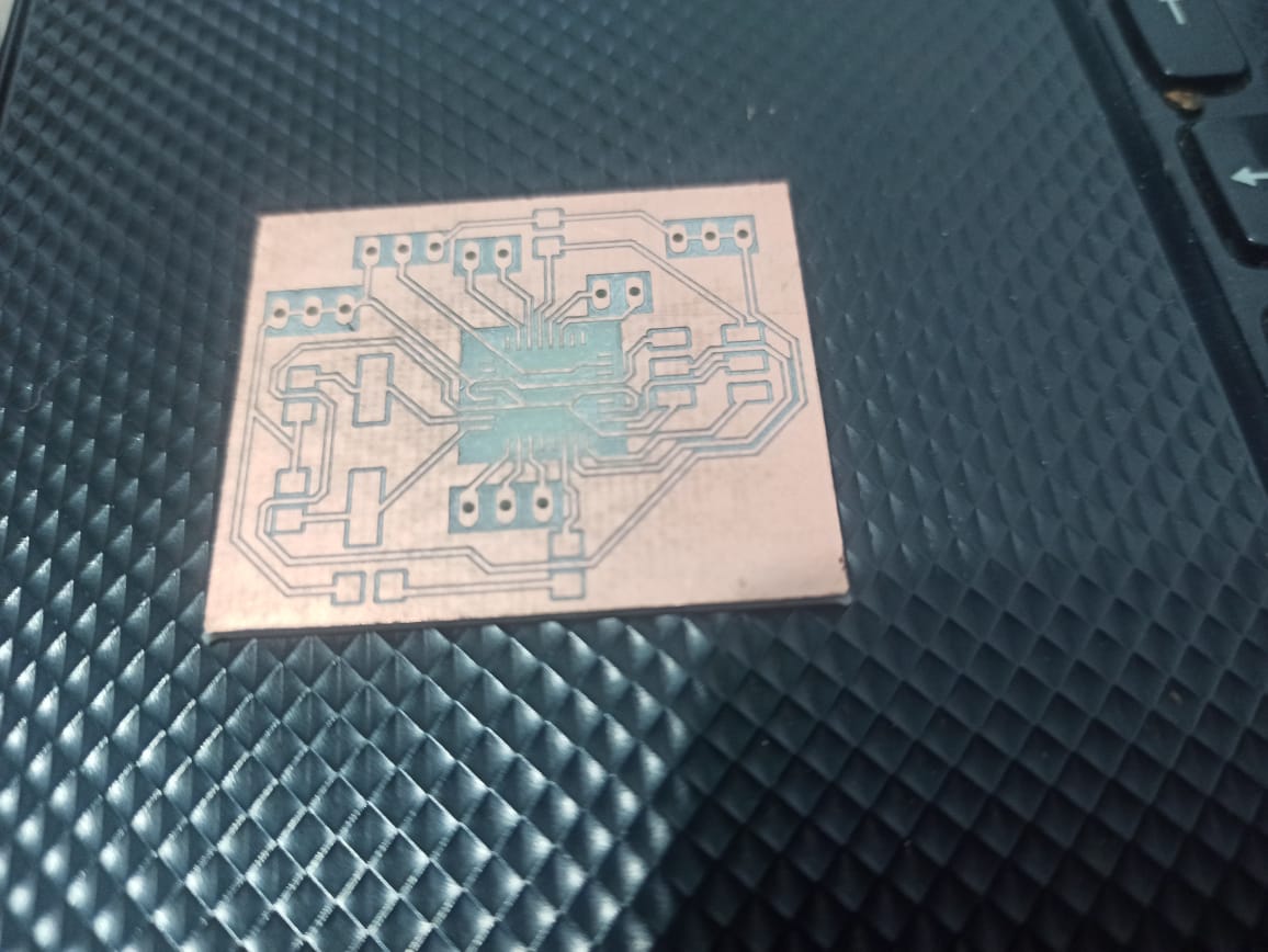
After this step now it is time to mill the board .I used the LPKF Cnc
For this machine, we command & generate the g-code using the machine software. It works with GERBER file generated from Eagle
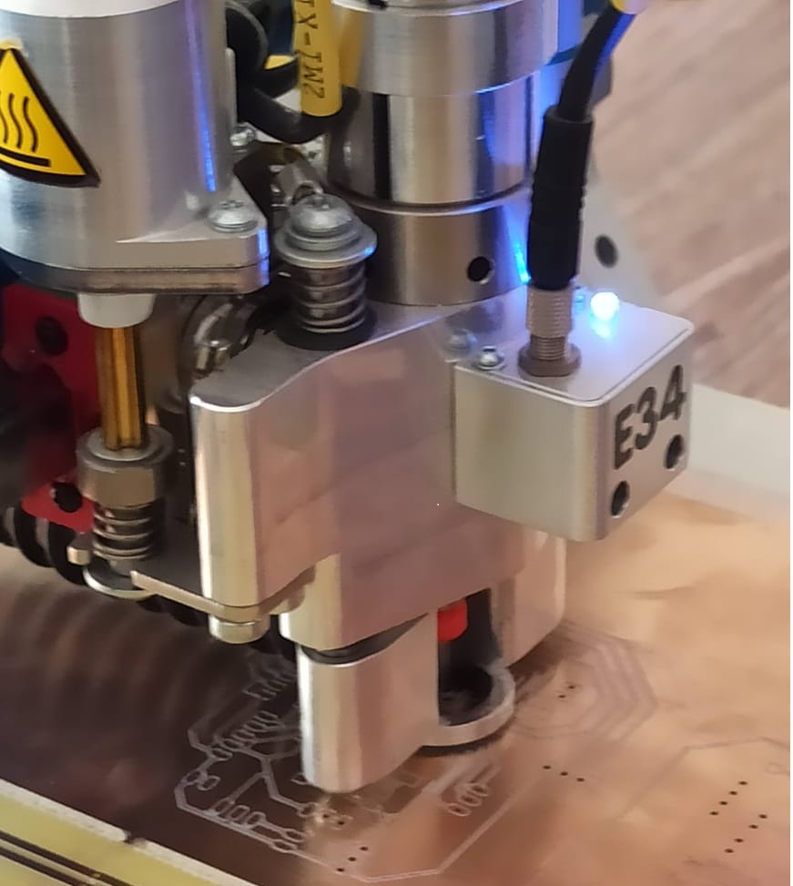
here it is the final result
Ater making sure that the board is well done , i assembled all the components as showing on the board file

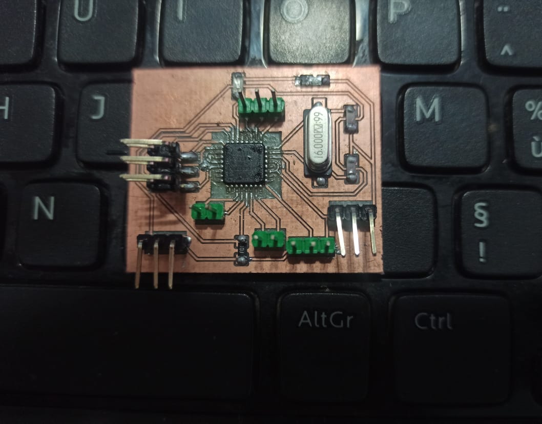
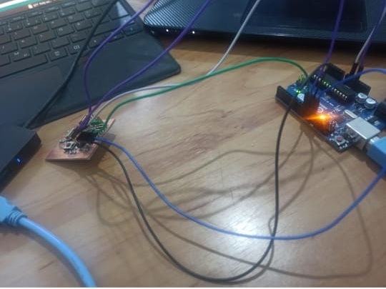
it looks fine and to make sure i had to program it so i can read the temperature and the humidity from the DHT 11 at first i tried to program the board using the FTDI but it didn’t work so i used th arduino to program it based on the fomllowing connections
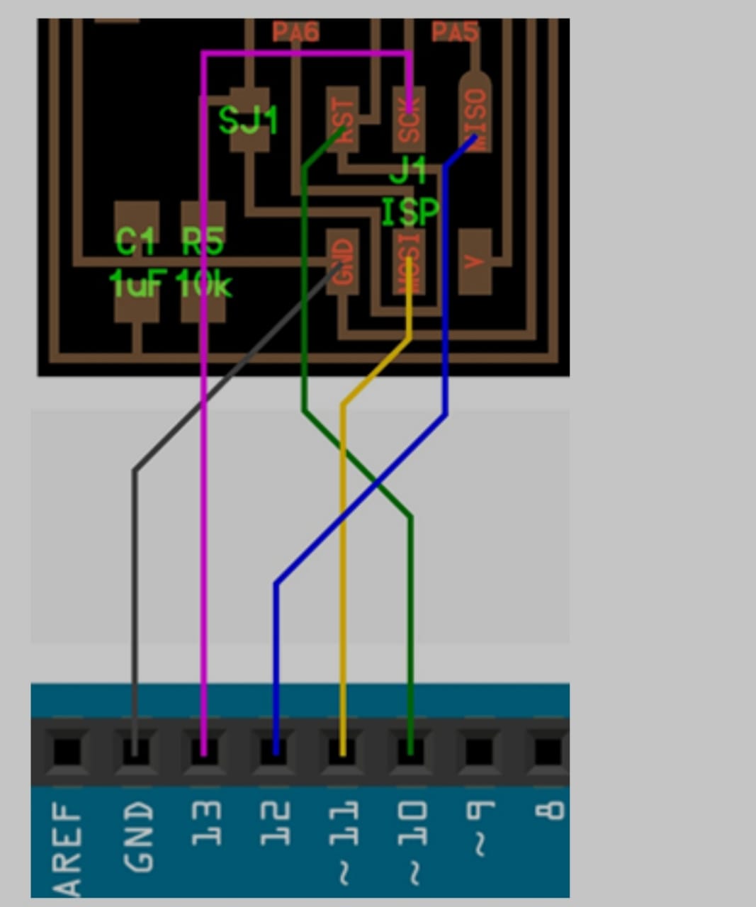
i uploaded this code
    #include <dht.h>


#define dht_apin A0 // Analog Pin sensor is connected to

dht DHT;

void setup(){

Serial.begin(9600);
delay(5000);//Delay to let system boot


 }//end "setup()"

void loop(){
//Start of Program

DHT.read11(dht_apin);

Serial.print("Current humidity = ");
Serial.print(DHT.humidity);
Serial.print("%  ");

Serial.print("temperature = ");
Serial.print(DHT.temperature);
Serial.println("C  ");
delay(500)
}
After making sure that the code is done uploading to the atmega328p microcontroller , i had to connect the FTDI to the board using the pins RX TX GND VCC so i can see what the arduino send to the serial com otherwise i will not be able to see anythig without the RX TX
and yes i was able to read the temperature and the humidity
chek the code
check this video