9. Embedded programming
This week is Embedded Programming. I must say its a very new topic for me and has a lot to learn .I need to work alongside my group to compare the performance and development workflows for other architectures. In addition i need to read a microcontroller data sheet. Program my board to do something, with as many different programming languages and programming environments as possible as an individual work .
Group assignment
to Check what we have done to compare the performance and development workflows for other architectures. click on this link
Individual assignment
What is datasheet?
A datasheet, data-sheet, or spec sheet is a document that summarizes the performance and other characteristics of a product, machine, component (e.g., an electronic component), material, subsystem (e.g., a power supply), or software in sufficient detail that allows a buyer to understand what the product is and a design engineer to understand the role of the component in the overall system. Typically, a datasheet is created by the manufacturer and begins with an introductory page describing the rest of the document, followed by listings of specific characteristics, with further information on the connectivity of the devices. In cases where there is relevant source code to include, it is usually attached near the end of the document or separated into another file. Datasheets are created, stored, and distributed via product information management or product data management systems
What does datasheet contain?
Manufacturer’s name
Product number and name
List of available package formats (with images) and ordering codes
Notable device properties
Short functional description
Pin connection diagram
Absolute minimum and maximum ratings :
supply voltage, power consumption, input currents, temperatures for storage, operating, soldering, etc
*Recommended operating conditions (as absolute minimum and maximum ratings)
DC specifications (various temperatures, supply voltages, input currents, etc.)
Maximum power consumption over the whole operating temperature range
AC specifications (various temperatures, supply voltages, frequencies, etc
Input/output wave shape diagram
Timing diagram
What Factors Are Important to choose Micro-Controller?
Memory
Temperature
Pin Configuration
Clock Speed
Chip Architecture
Special Features
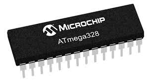
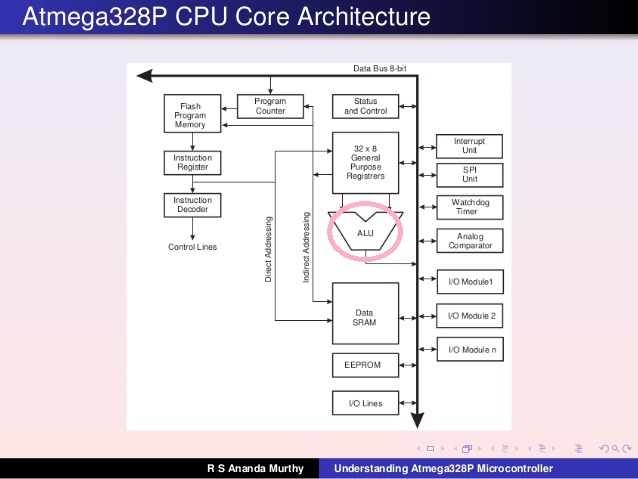
First of all, it is essential to read the board’s datasheet to understand the properties and possible functions I can work out using this board. This is some of the basic info about the microcontroller ATmega-328 !
Overview
ATmega-328 is basically an Advanced Virtual RISC (AVR) micro-controller. It supports the data up to eight (8) bits. ATmega-328 has 32KB internal builtin memory. This micro-controller has a lot of other characteristics.
ATmega 328 has 1KB Electrically Erasable Programmable Read Only Memory (EEPROM). This property shows if the electric supply supplied to the micro-controller is removed, even then it can store the data and can provide results after providing it with the electric supply.
Moreover, ATmega-328 has 2KB Static Random Access Memory (SRAM).
ATmega 328 has several different features which make it the most popular device in today’s market. These features consist of advanced RISC architecture, good performance, low power consumption, real timer counter having separate oscillator, 6 PWM pins, programmable Serial USART, programming lock for software security, .
Pinout schematics
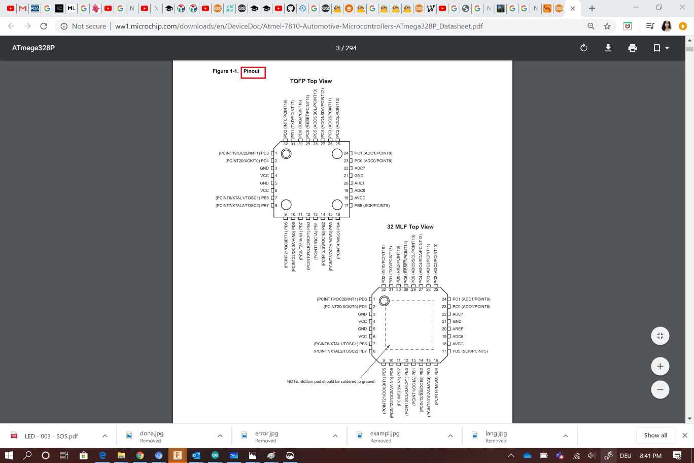
Pin description
PWM = 6 pins OC0A (PD6), OC0B (PD5), 0C1A (PB1), OC1B (PB2), OC2A (PB3),OC2B (PD3)
The pins of the PORTC can be converted by an Analog toDigital converter.
Analog to Digital Converter (10bit resolution) = 6 multiplexed inputs ADC0 (PC0) to ADC5 (PC5)
I2C bus management (TWI Two Wire Interface) = the bus is operated via the pins SDA (PC5) / SCL (PC4).
Serial port (USART) = serial send / receive via TXD (PD1) / RXD (PD0) pins
Analog comparator = pins AIN0 (PD6) and AIN1 (PD7) can trigger interruption
Programmable Watchdog Timer
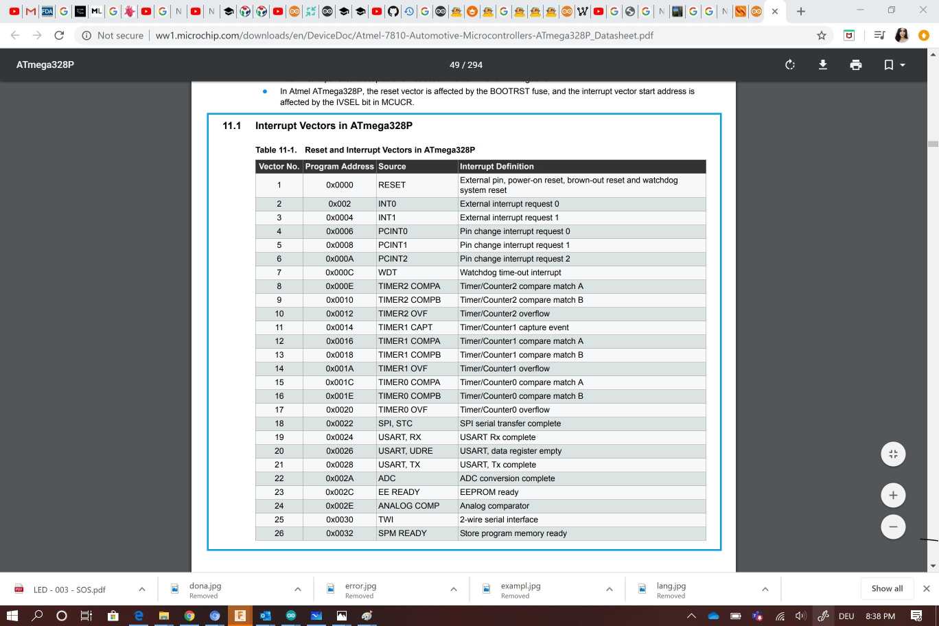
Interruption management (24 possible sources (see interrupt vectors)): summary
-
Interruptions related to the INT0 (PD2) and INT1 (PD3) inputs
-
Interruptions on change of state of pins PCINT0 to PCINT23
-
Interruptions related to Timers 0, 1 and 2 (several configurable causes)
-
Interruption related to the analog comparator
-
End of ADC conversion interruption
-
Interruptions of the USART serial port
Interrupt vectors
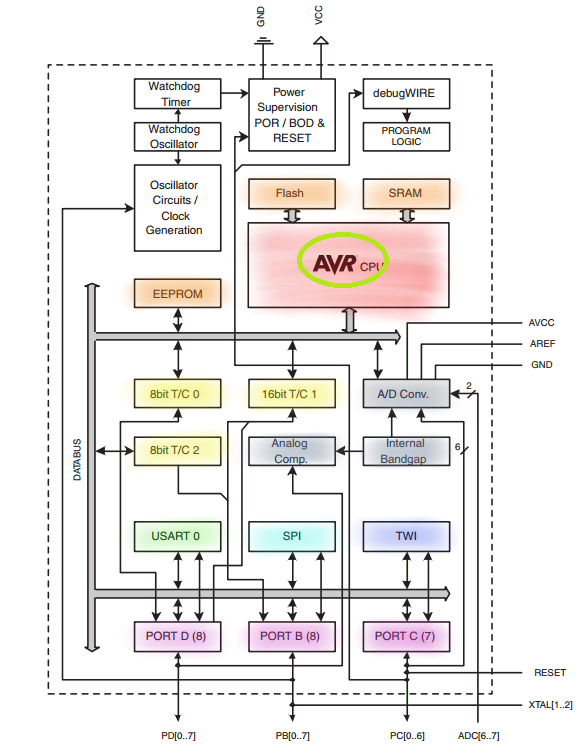
Architechture
Getting started with Arduino IDE
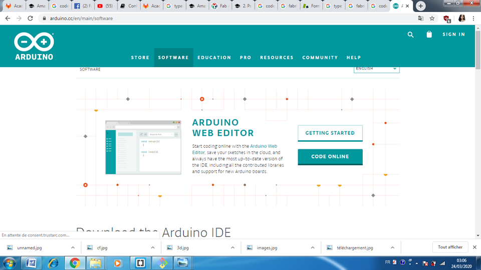
The Arduino Integrated Development Environment (IDE) is a cross-platform application (for Windows, macOS, Linux) that is written in functions from C and C++. It is used to write and upload programs to Arduino compatible boards, but also, with the help of 3rd party cores, other vendor development boards The first step is to download the software from here
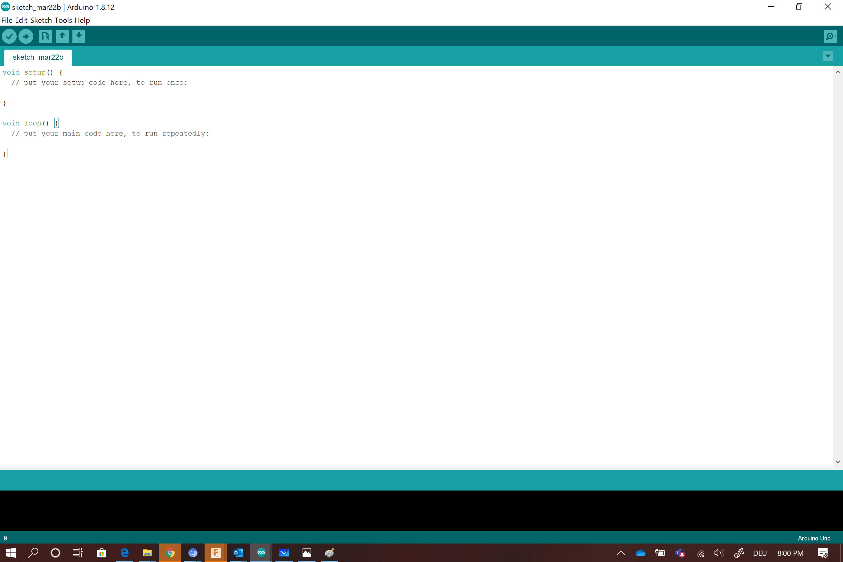
This is what you should find as interface
To program my arduino board i used the tools option to choose arduino UNo
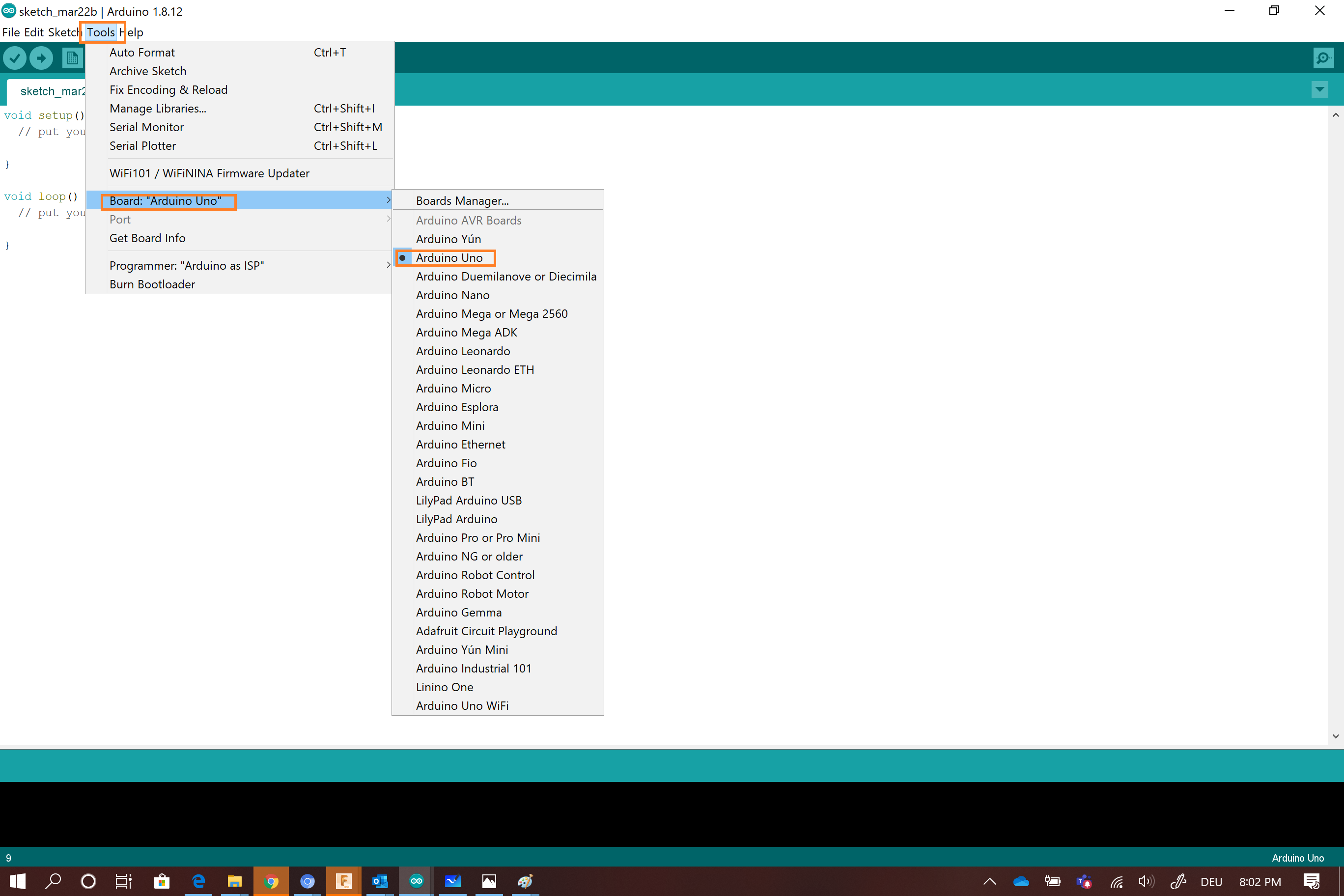
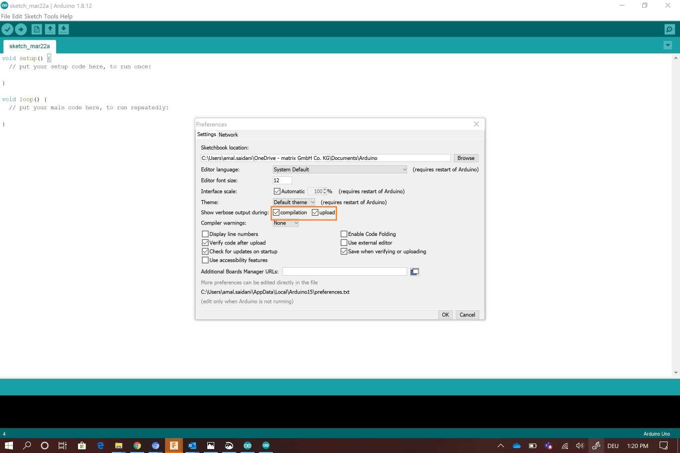
It’s important to unable some preferences to facilitate the compilation task
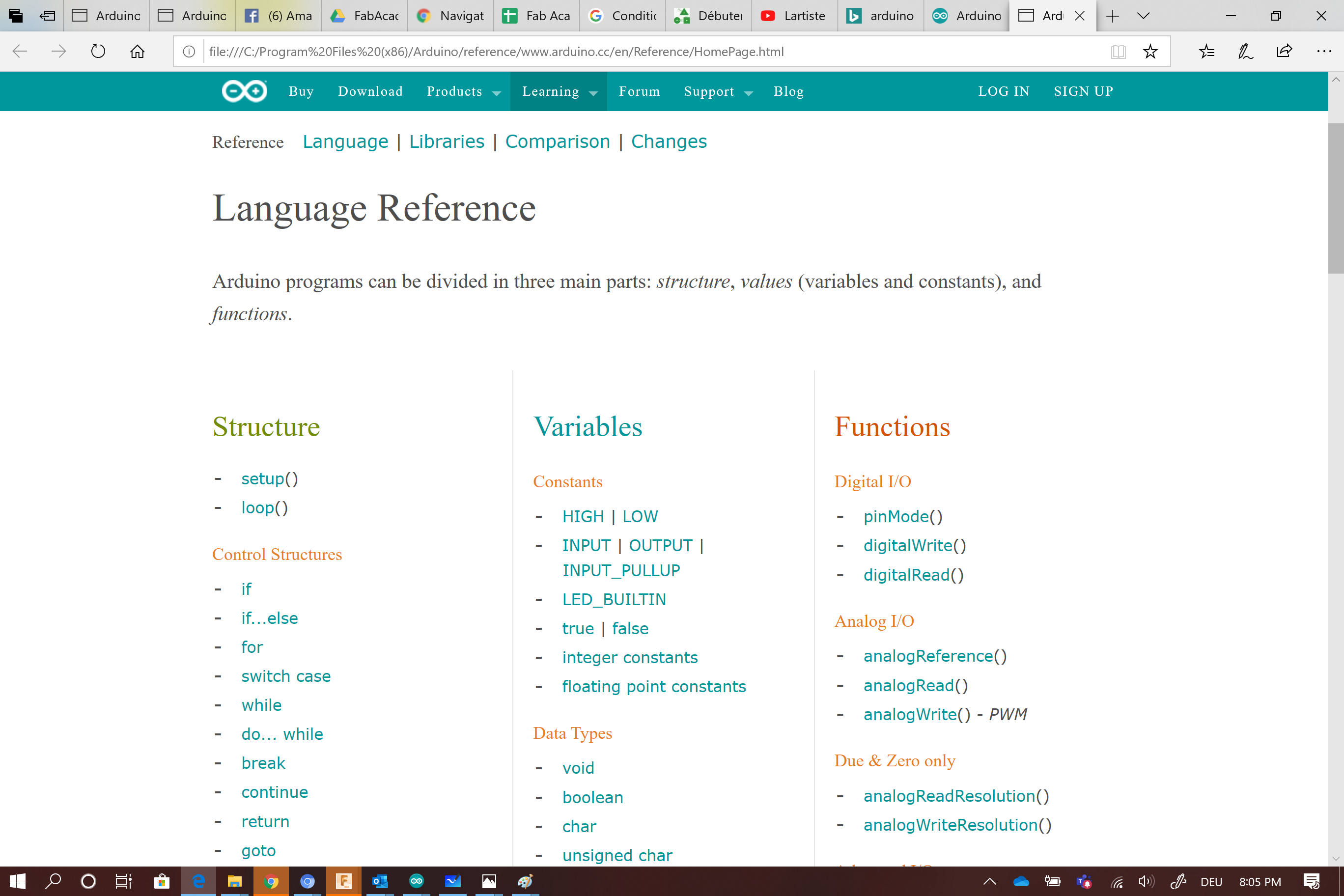
I used the refernce page to learn more about the arduino language
I started by descovering some basics examples on Arduino like the blink function

Then i decided to create my own as howing bellow !! First i try to blink the LED using arduino language
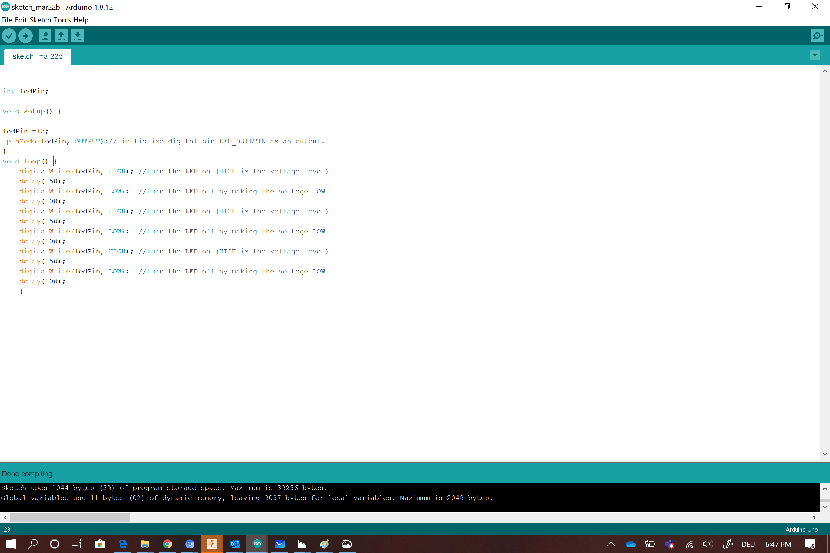
This code seems a bit long and contains repetitive lines ! I guess i can make it shorter and more efficient ! Here it is the result
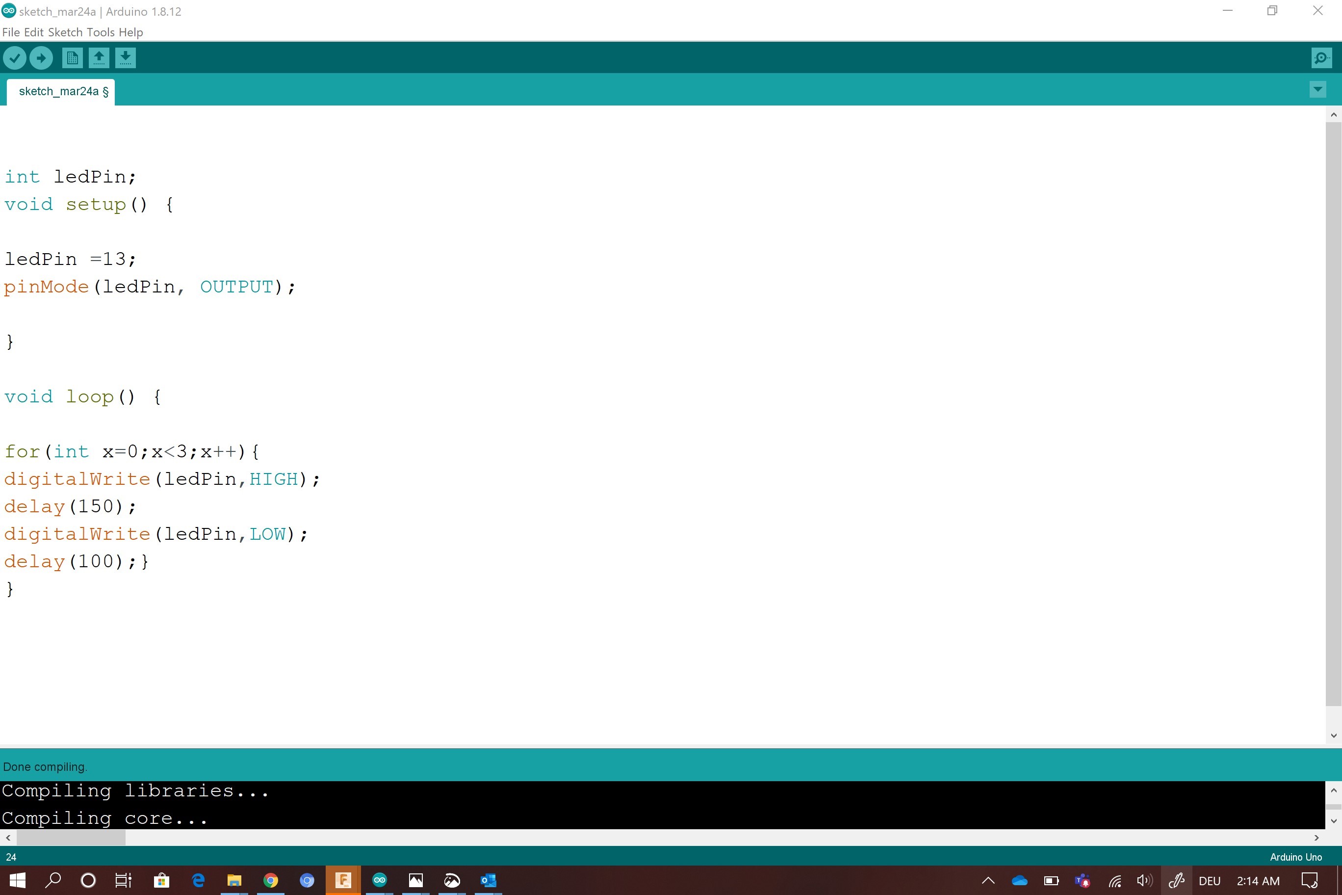
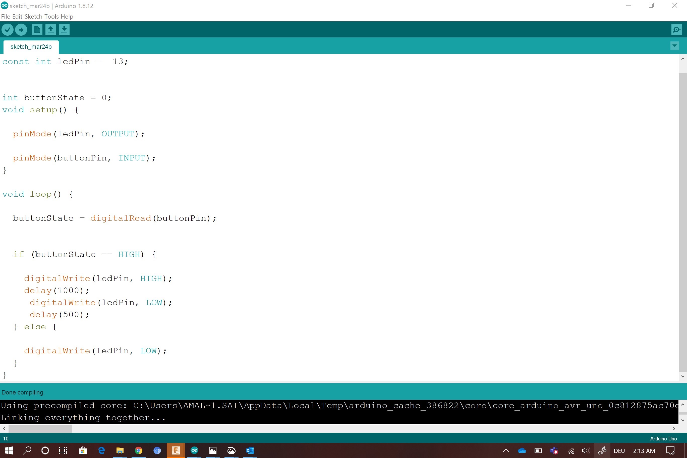
Another function
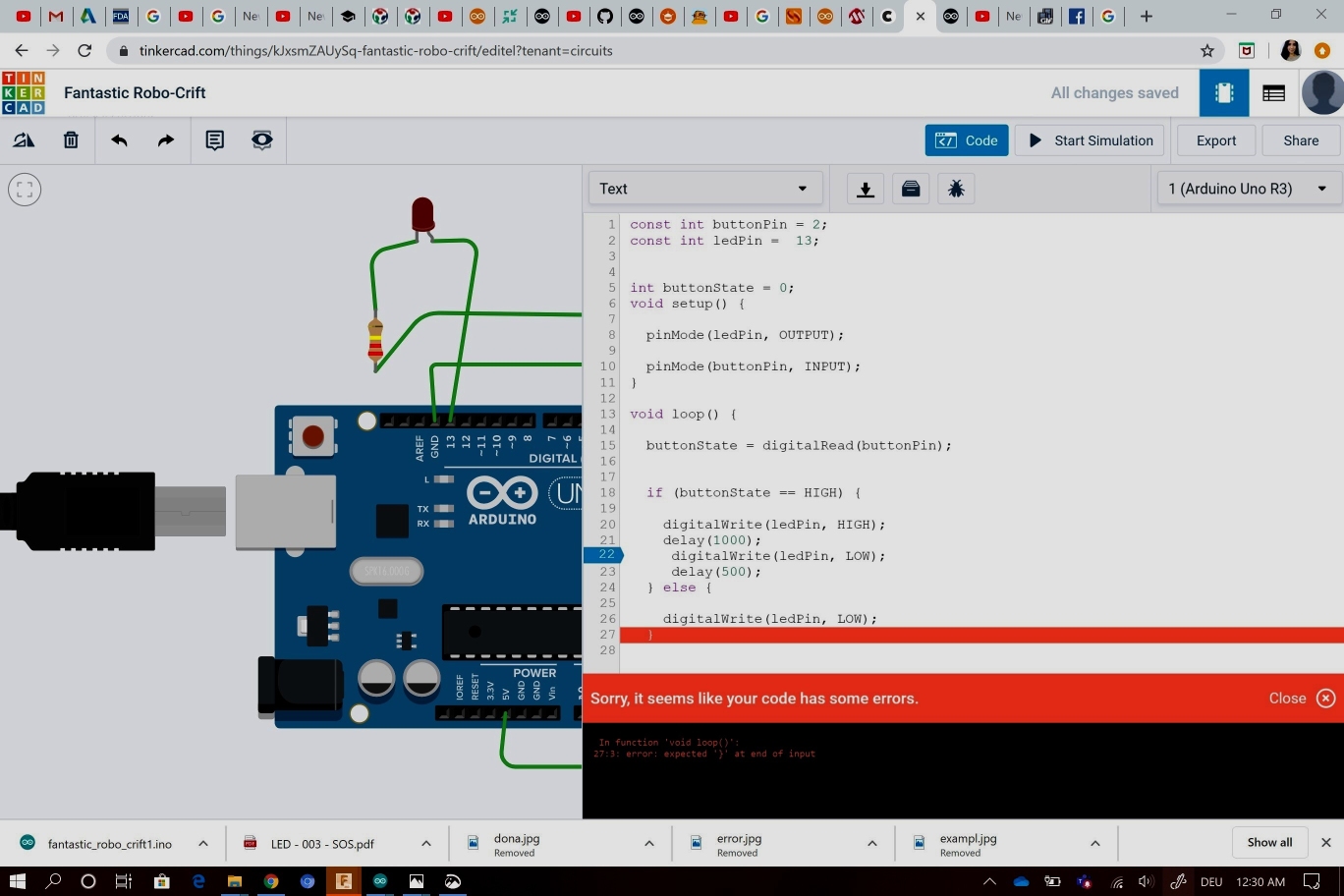
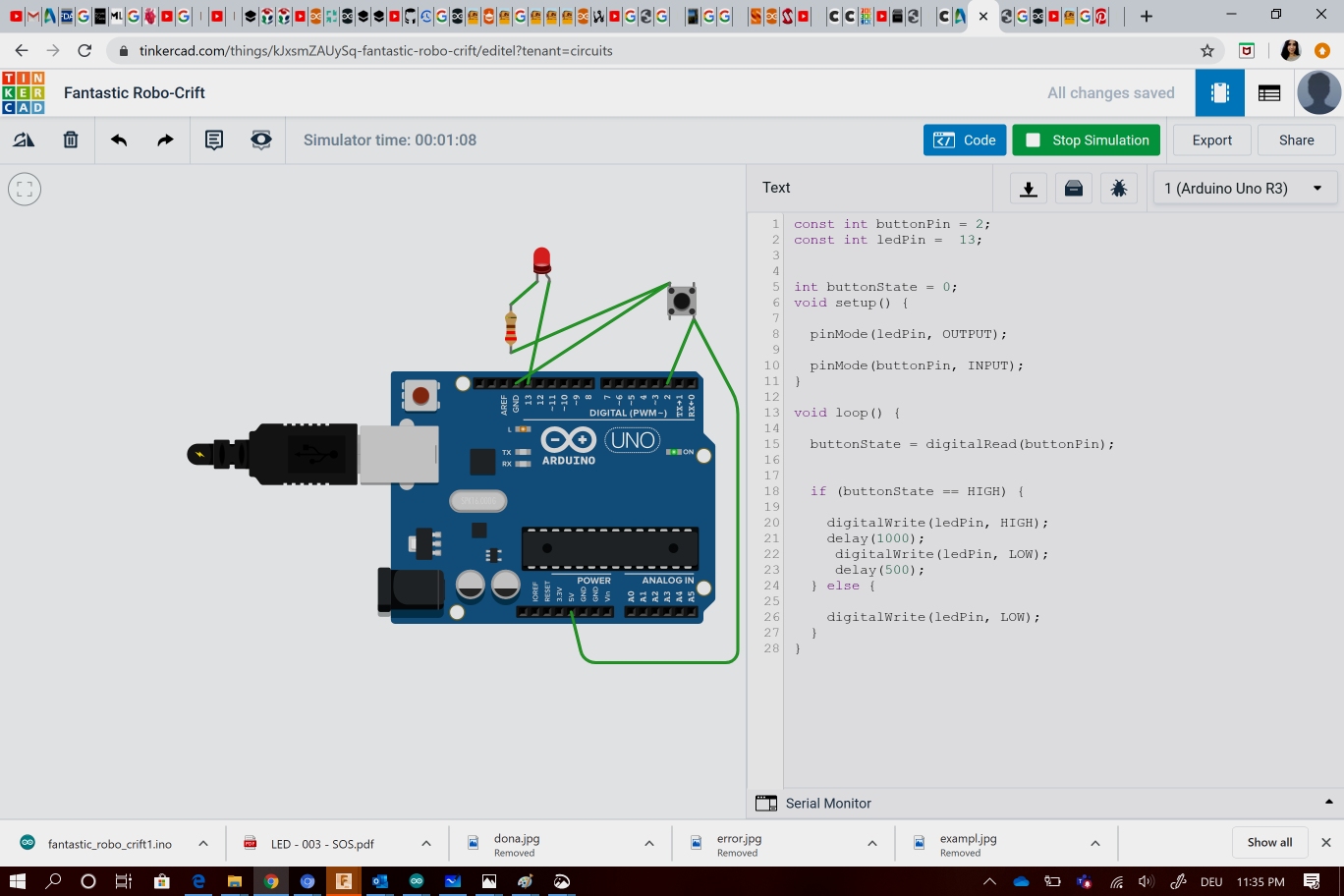
I added the pushbuttom to control the LED blink
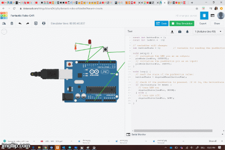
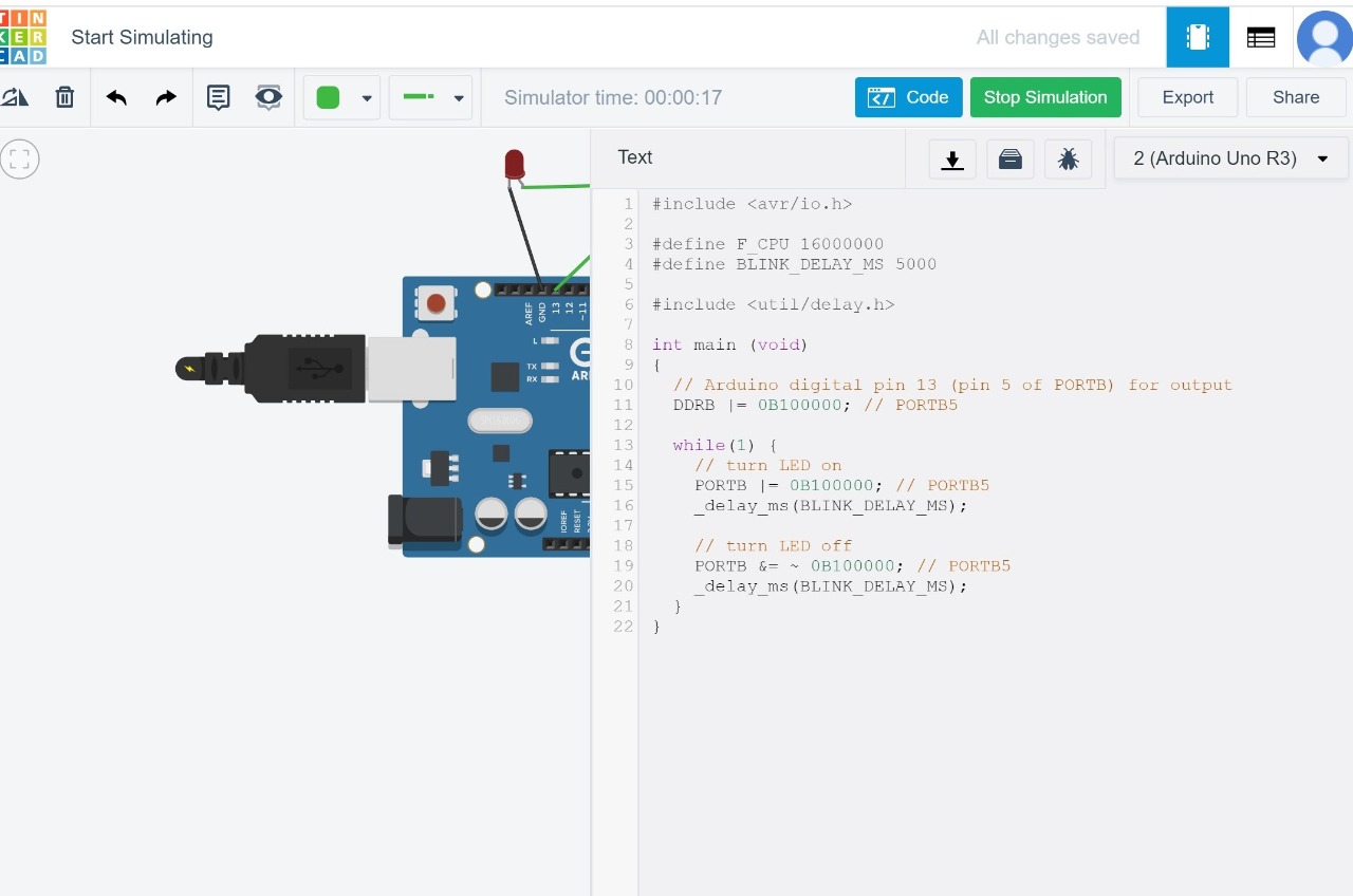
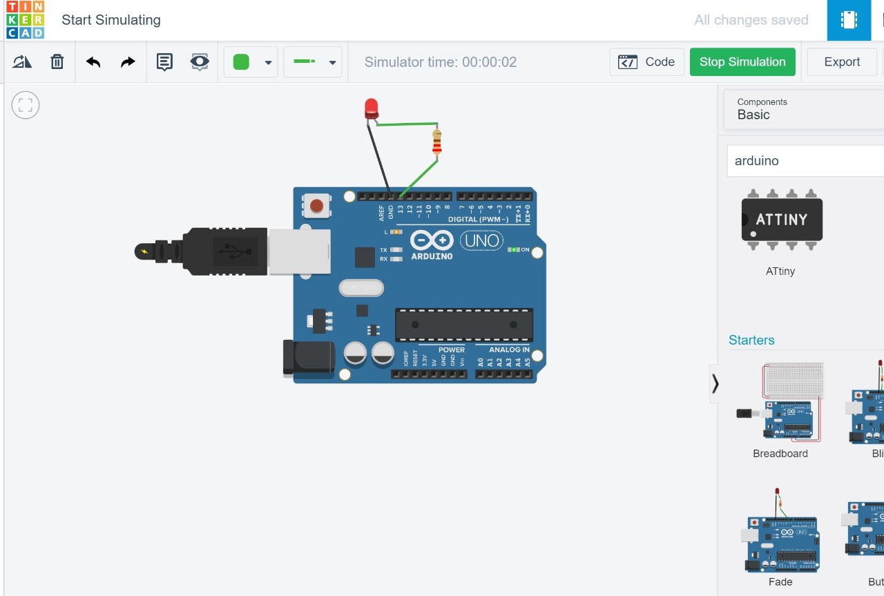
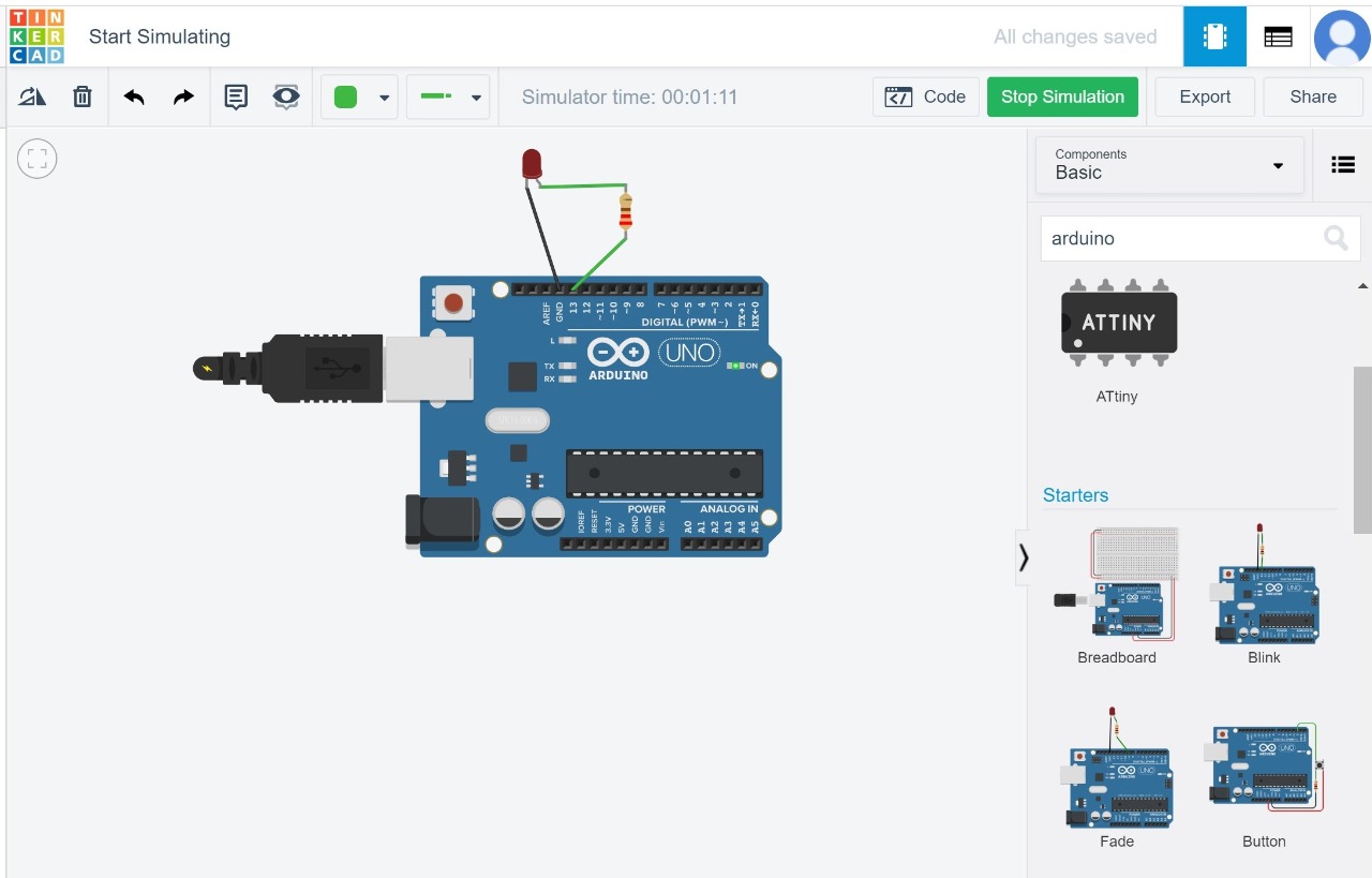
Now it’s time to simulate my codes ! Unfortunately I ‘m not able to acces the fab lab due to the covid-19 crisis , That’s why i decided to simulate it using a software called thinkercad
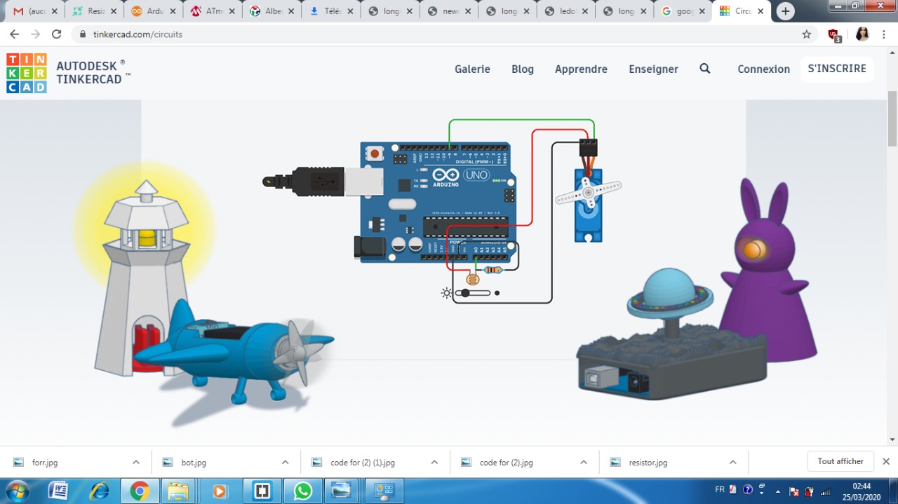
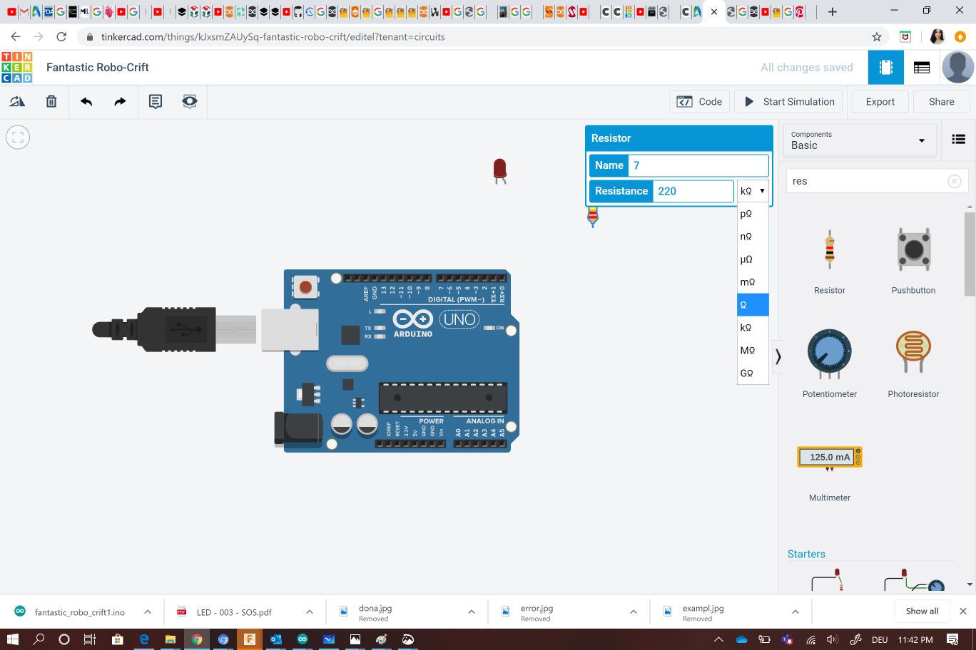
I choose arduino from the circuits list then i sarched for the needed componenets on the basics arduino components as the LED , the RESISTOR and the pushutton.
For the resistor you can choose the resistance that you need by yourself , in my case i applied for 220 Ω resistance value
I simuated the arduino using my first code and the LED blink successfully!
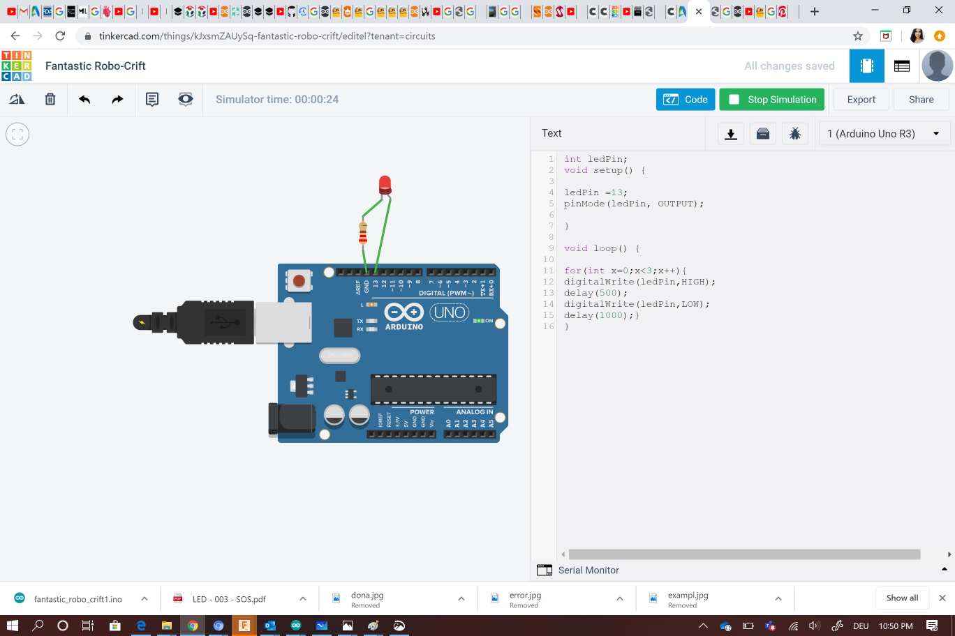
After that , I checked the other code .
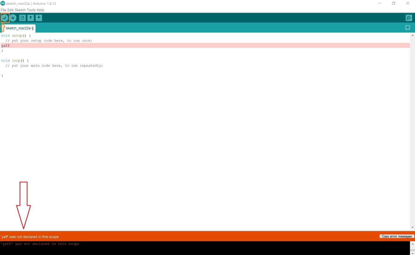
At first i faced an issue , it seems like my code has some errors as the software shows
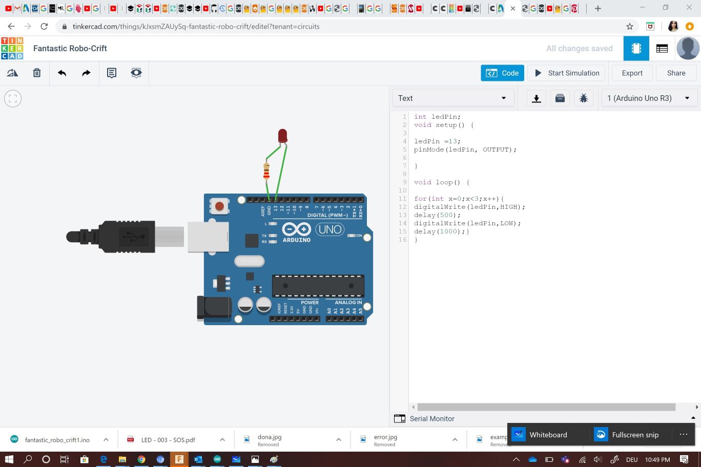
 I corrected the code error and the led blink successfully
Programming my own board
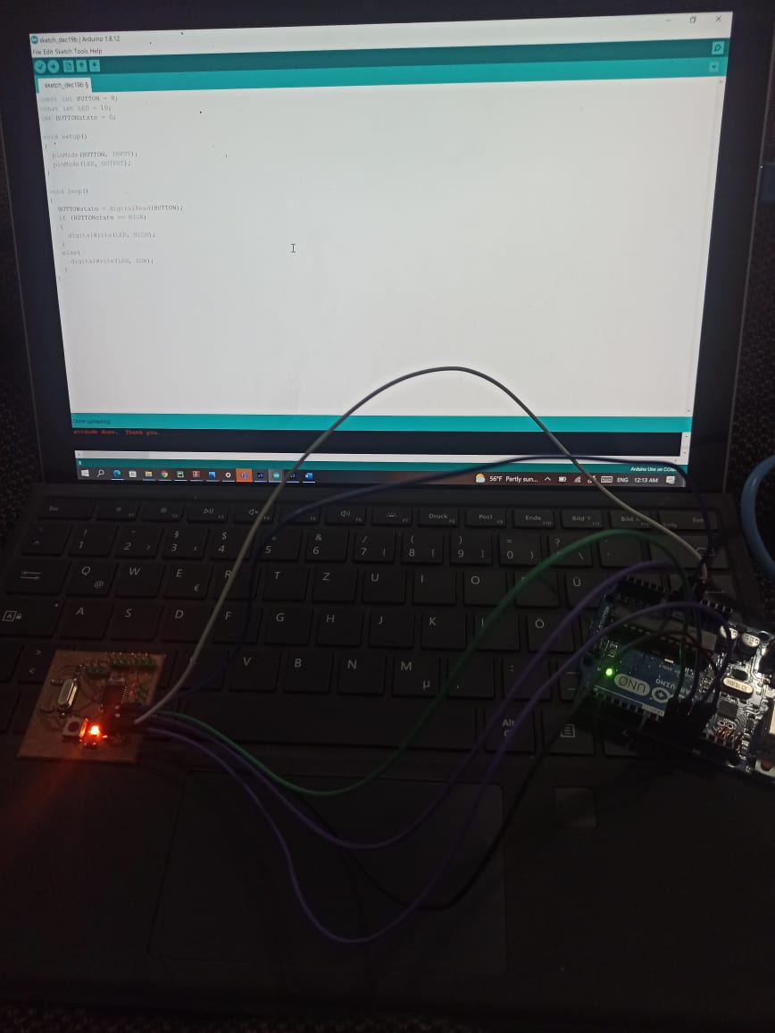
After the corona virus pandemis has declined in my country and i became able to deplace to the fablabs , our intructor told us that we need to program our own boards , At first i tried to use my hello board from the week electronic design but unfortunately the microcontroller has been damaged and the case that i didn’t find the same microcontroller attiny44 smd available in my country that’s why i made another hello board with the same components but i used atmega328p microcontroller .
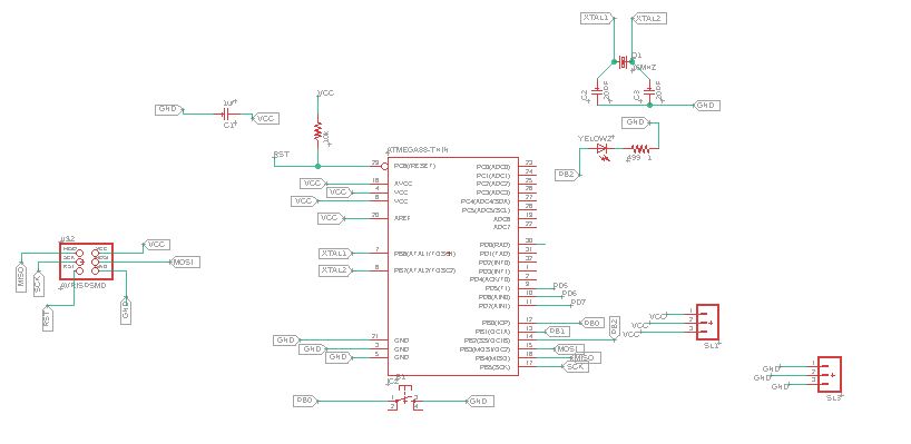
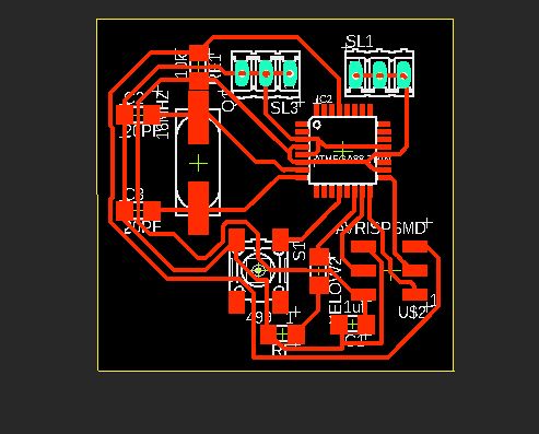
And here it is my board after soldering all the components

Now it is time to run the code but first i uploaded the code Arduino as ISP so the arduino will be the programmer
Then i burned the bootloader so the microcontroller can recieve the code i send
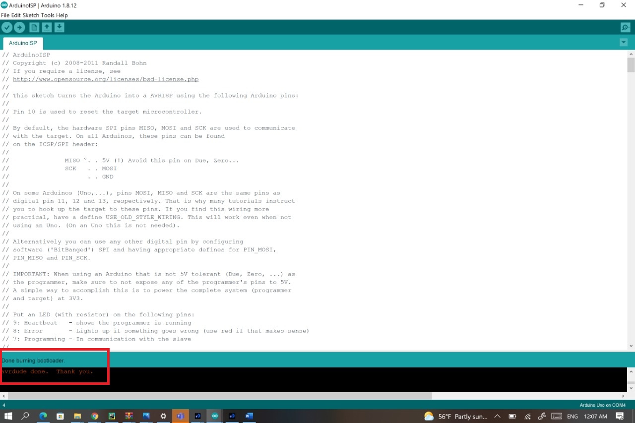
Then i uploaded the sketch , sketch-> upload using programmer
I tried the same code of the LED and the pushbutton i used with arduino in thinkercad with my own board and here it is the result
What Does C Programming Language (C) Mean?
C is a high-level and general-purpose programming language that is ideal for developing firmware or portable applications. Originally intended for writing system software, C was developed at Bell Labs by Dennis Ritchie for the Unix Operating System in the early 1970s.Ranked among the most widely used languages, C has a compiler for most computer systems and has influenced many popular languages – notably C++
Input / Output
is via special variables called “registers”.Registers are actual hardware memory locations inside the μC. Their names and sizes are predefined.
• When we assign a value to these registers in the program, the actual value in the hardware changes.These values can be changed multiple times at any point in the program
I/O Registers
• There are 3 registers that control the I/O pins: DDR, PORT and PIN .Each port has it’s own registers. Hence, port A has registers DDRA, PORTA, PINA; port B has registers DDRB, PORTB, PINB; and so on.
• DDR, PORT and PIN serve different functions.
DDR (Data direction register)
decides whetherthe pins of a port are input pins or output pins.
• If the pin is input, then the voltage at that pin is undecided until an external voltage is applied.
• If the pin is output, then the voltage at that pin is fixed to a particular value (5V or 0)
PORT
The bits on the PORT register correspond to the pins of the associated port in the same manner as in the case of the DDR register.
• PORT is used to set the output value.
• If the pin is set as output, then a PORT value of 1 will set voltage at that pin to 5V.
•If PORTvalue is 0, then voltage is set to 0.
Here it is my code i use it toblink an LED for 5000 ms (5sec) qnd then turned it off again
The same case i had to blink the LED using C code but with my board and here it is the result
check my files